EP0300974A1 - Equipement de capteur inductif - Google Patents
Equipement de capteur inductif Download PDFInfo
- Publication number
- EP0300974A1 EP0300974A1 EP88810504A EP88810504A EP0300974A1 EP 0300974 A1 EP0300974 A1 EP 0300974A1 EP 88810504 A EP88810504 A EP 88810504A EP 88810504 A EP88810504 A EP 88810504A EP 0300974 A1 EP0300974 A1 EP 0300974A1
- Authority
- EP
- European Patent Office
- Prior art keywords
- coil
- excitation coil
- coils
- receiver
- receiver coils
- Prior art date
- Legal status (The legal status is an assumption and is not a legal conclusion. Google has not performed a legal analysis and makes no representation as to the accuracy of the status listed.)
- Granted
Links
- 230000001939 inductive effect Effects 0.000 title claims abstract description 11
- 230000005284 excitation Effects 0.000 claims abstract description 64
- 238000012937 correction Methods 0.000 claims description 19
- 238000000034 method Methods 0.000 claims description 3
- 230000010363 phase shift Effects 0.000 claims 1
- 230000006698 induction Effects 0.000 abstract 1
- 230000032683 aging Effects 0.000 description 4
- 230000005672 electromagnetic field Effects 0.000 description 4
- 238000010586 diagram Methods 0.000 description 3
- 230000006870 function Effects 0.000 description 3
- 238000004804 winding Methods 0.000 description 3
- 230000004913 activation Effects 0.000 description 2
- 238000005516 engineering process Methods 0.000 description 2
- 238000011156 evaluation Methods 0.000 description 2
- 238000005259 measurement Methods 0.000 description 2
- 230000007935 neutral effect Effects 0.000 description 2
- 230000035945 sensitivity Effects 0.000 description 2
- 230000006399 behavior Effects 0.000 description 1
- 239000003990 capacitor Substances 0.000 description 1
- 239000000969 carrier Substances 0.000 description 1
- 230000007423 decrease Effects 0.000 description 1
- 230000001419 dependent effect Effects 0.000 description 1
- 238000013461 design Methods 0.000 description 1
- 238000001514 detection method Methods 0.000 description 1
- 238000006073 displacement reaction Methods 0.000 description 1
- 230000000694 effects Effects 0.000 description 1
- 230000005294 ferromagnetic effect Effects 0.000 description 1
- 230000005669 field effect Effects 0.000 description 1
- 239000002184 metal Substances 0.000 description 1
- 238000003825 pressing Methods 0.000 description 1
- 238000007639 printing Methods 0.000 description 1
- 230000001681 protective effect Effects 0.000 description 1
- 230000000717 retained effect Effects 0.000 description 1
- 230000035882 stress Effects 0.000 description 1
- 239000000758 substrate Substances 0.000 description 1
Images


Classifications
-
- G—PHYSICS
- G01—MEASURING; TESTING
- G01V—GEOPHYSICS; GRAVITATIONAL MEASUREMENTS; DETECTING MASSES OR OBJECTS; TAGS
- G01V3/00—Electric or magnetic prospecting or detecting; Measuring magnetic field characteristics of the earth, e.g. declination, deviation
- G01V3/08—Electric or magnetic prospecting or detecting; Measuring magnetic field characteristics of the earth, e.g. declination, deviation operating with magnetic or electric fields produced or modified by objects or geological structures or by detecting devices
- G01V3/10—Electric or magnetic prospecting or detecting; Measuring magnetic field characteristics of the earth, e.g. declination, deviation operating with magnetic or electric fields produced or modified by objects or geological structures or by detecting devices using induction coils
- G01V3/104—Electric or magnetic prospecting or detecting; Measuring magnetic field characteristics of the earth, e.g. declination, deviation operating with magnetic or electric fields produced or modified by objects or geological structures or by detecting devices using induction coils using several coupled or uncoupled coils
- G01V3/105—Electric or magnetic prospecting or detecting; Measuring magnetic field characteristics of the earth, e.g. declination, deviation operating with magnetic or electric fields produced or modified by objects or geological structures or by detecting devices using induction coils using several coupled or uncoupled coils forming directly coupled primary and secondary coils or loops
- G01V3/107—Electric or magnetic prospecting or detecting; Measuring magnetic field characteristics of the earth, e.g. declination, deviation operating with magnetic or electric fields produced or modified by objects or geological structures or by detecting devices using induction coils using several coupled or uncoupled coils forming directly coupled primary and secondary coils or loops using compensating coil or loop arrangements
-
- G—PHYSICS
- G01—MEASURING; TESTING
- G01V—GEOPHYSICS; GRAVITATIONAL MEASUREMENTS; DETECTING MASSES OR OBJECTS; TAGS
- G01V13/00—Manufacturing, calibrating, cleaning, or repairing instruments or devices covered by groups G01V1/00 – G01V11/00
Definitions
- the invention relates to an inductive sensor device with one, but preferably at least two receiver coils and at least one primary excitation coil connected to an HF generator for inducing, preferably identical, voltages in the receiver coils that can be predetermined in an undisturbed state.
- Inductive sensor devices which contain one or more excitation coils which generate an electromagnetic field, and in the immediate vicinity of the excitation coils, receiver coils which are exposed to this field and whose arrangement and shape are designed such that either a receiver coil is in the neutral center of the electromagnetic excitation field or two or more receiver coils are present which generate partial voltages and in which, by connecting voltages from receiver coils to one another at the common outputs, no voltage always occurs when the system is in a completely balanced state. In this state, no sensor signal is generated in the downstream electronic part of such a sensor receiving circuit, consisting of two or more receiver coils. As long as nothing changes in the field distribution of the excitation coils or in the spatial assignment to the receiver coils, the balanced state is retained.
- Adjustment can mean zero value or predeterminable threshold value.
- an aftermath occurs on the receiver coils or their combination Amount and / or phase changed voltage. This phenomenon is as a sensor function desired and is used to obtain position-indicating or workpiece-identifying signals at the output of the sensor electronics.
- disturbances of the balance in the electromagnetic field of the sensor arrangement can also occur due to other influences, such as thermal expansion of the sensor components, mechanical displacement of the different coil carriers against one another, changes in the sensor windings due to aging and also external influences on the protective shield of the sensor as a result of metal vapor deposits .
- These and other undesirable influences shift the symmetry of the sensor system, and differential voltages also occur at the outputs of the coil combinations, which are not recognized as error signals by the downstream electronics, which evaluate the magnitude and phase of the differential voltages, and instead simulate field changes caused by an object to which the sensor is supposed to respond could result and thus give corresponding output signals.
- These signals shift the operating point of the sensor system and mean faulty sensor function.
- the object of the invention is now to design the sensor devices specified at the outset in such a way that it is possible to precisely match the device again and again at any time intervals even after its assembly and in the course of operation and to maintain the achieved calibration until a next calibration cycle.
- the sensor device with which the object is achieved, is characterized by at least one additional excitation coil and means for supplying the same with a sinusoidal alternating current of the same frequency, in order to make the partial voltages induced in the receiver coil or coils the same when an error occurs, i.e. Compensate for errors (voltage or phase).
- the additional excitation coil can also be supplied with a sub-harmonic or harmonic frequency of the primary excitation coil; only the evaluation circuit would have to be adapted accordingly to the frequency of the compensated electromagnetic field.
- the additional excitation coil or coils which can be accommodated in a manner similar to the primary excitation coil (s) of the sensor device, with an additional current of the same frequency, variable phase and / or variable amplitude, which is small in relation to the primary excitation current acted upon, wherein the additional coil (s) can be either symmetrical to the primary excitation coil and / or to the receiver sub-coils or asymmetrical to them.
- the alternating current flowing in the additional coil also generates an electromagnetic field either in the same phase position or in a changed phase against the primary excitation field.
- the sum of the subfields is the total field acting on the receiver coils. If this is not symmetrical beforehand, the symmetry can be restored in a suitable manner by appropriately loading the additional coil with an alternating current of variable amplitude and / or phase.
- any desired asymmetry can also be generated in the exciter or receiver field - e.g. with curved workpiece course; the amplifier and the evaluation arrangement could then be designed such that a sensor signal is evaluated above or below a predeterminable threshold value instead of above / below the zero value.
- the additional coil has a cylindrical, rectangular or flat shape. It can also be composed of several partial coils, so that all corresponding sensor forms can be provided with such additional coils in the same way and function in principle.
- the adjustment can be carried out automatically at arbitrary time intervals, which can be acted upon with a control signal corresponding to the difference between the voltages induced in the partial receiver coils.
- the controller contains means for supplying the value of the difference to a non-volatile program memory and means for subsequently supplying the value contained in the memory as a manipulated variable to the means for feeding the additional excitation coil.
- FIG. 1 shows the principle of one of several possible multi-coil sensor devices in the simplest embodiment.
- the device here has two identical receiver coils 1 and 2, which are connected to one another and are connected together to an amplifier 3.
- An RF generator 4 for excitation sends a current through a primary excitation coil 5, which is arranged between the two receiver coils 1 and 2.
- phase comparator 3a which is connected to the amplifier 3. This serves for the phase comparison of the receiver coil differential voltage present at the amplifier input 3b when the symmetry is disturbed.
- the phase comparison enables the direction detection of a sensor deviation.
- an additional excitation coil 6 is used according to the invention for correction.
- the coil 6 consists of a single turn with a center tap.
- the coil 6 is connected to the secondary side 7b of a isolating transmitter 7 connected to the HF generator 4, and the center tap of the coil is connected to the tap of a potentiometer 8 which is also connected to the secondary side 7.
- the tap of the potentiometer 8 is in its central position, the same current flows in the two half-turns of the coil 6, and the field remains unchanged when the coil 6 is arranged exactly symmetrically in the sensor system.
- FIG. 2 and 3 a structure is shown as an example of a combined flat sensor, which has two ring-shaped carrier disks 9 and 10, each with two flat receiver coils 11 and 12 or 11 'and 12' arranged symmetrically to the sensor axis A.
- the coils 11 'and 12' are rotated against the coils 11 and 12 by 90 ° in the plane in order to give the sensor a 4-quadrant behavior, ie to enable output signals that are based on the position of a metallic body within the ring make statements in all four quadrants.
- the primary excitation coil 15 is located, for example, between the two ring disks 9 and 10.
- Such flat sensors are also known and are described, for example, in EP-A-0 130 940.
- an additional excitation coil 16 is arranged coaxially to the primary excitation coil 15, which, like the coil 6 in FIG. 1, can be designed and fed to correct alignment errors of the coils 11, 12, 11 ', 12' and 15.
- the sensor coils could also be distributed on carrier disks differently than shown in FIG. 2.
- one of the disks can carry one or two pairs of receiver coils, such as coils 11 and 12 and 11 'and 12', while another disk carries the primary excitation coil 15.
- the additional excitation coil 16 could then be carried on a separate carrier disk, on the carrier disk of the receiver coils or on the carrier disk of the primary excitation coil.
- Multilayer technology and multiple printing on substrates offer a wide range of implementation options in practice.
- FIG. 4 schematically shows another possibility of feeding a split additional excitation coil, such as the coil 16 of FIG. 2 carried on a carrier disk.
- the coil 16 is back to the Se secondary side 17b of an isolating transformer 17 connected to the HF generator 4.
- the center tap of the coil 16 is connected to the tap of a voltage divider, which is also connected to the secondary side 17b and consists of two electronically controllable resistors 18 and 19, for example field effect transistors.
- a control voltage is supplied from an amplifier 22, which is determined by the input signal of the amplifier 22.
- the controllable resistors 18 and 19, which are not described in more detail, can be controlled such that in the case of voltage zero at the input 23 of the amplifier 22, both resistors are the same, with a negative voltage at the input 23 the one resistance increases, the other decreases, and with a positive voltage vice versa.
- the primary excitation coil not shown in FIG. 4, is fed by the HF generator 4 via lines 25.
- the amplitude of the two partial currents in the correction coil is changed for correction.
- FIG. 5 illustrates another example in which the correction means allow a phase error in the sensor system to be compensated for by a phase-changing correction field.
- an additional excitation coil or correction coil 26 without center tap is provided, which is connected to a phase shifter circuit of a known type and is supplied by this with an HF voltage, the phase position of which can be changed.
- the phase shifter circuit consists in the embodiment of a resistor R and a capacitor C and two resistors R2 and R3.
- the resistor R is designed as an electronically controllable resistor which, like the resistors 18 and 19 in FIG. 4, is connected to an amplifier 32.
- the partial voltages on the limbs of the phase bridge are denoted by U R , U C , U2 and U3.
- the voltage supplied by the HF generator 4 is at the phase bridge.
- the coil 26 lies in the bridge diagonal with the voltage U4.
- FIG. 6 shows the vector diagram of the different voltages. It can be seen from this that the amplitude of the voltage U4 across the coil 26 remains the same for all resistance values of the controllable resistor R and that the phase of the current in the coil 26 can be varied within wide limits by controlling the resistor R alone.
- the field generated by the coil 26, which is superimposed on the field generated in a sensor device by the primary excitation coil, can thus change the phase of the overall field.
- the arrangement can e.g. by combining the exemplary embodiments according to FIGS. 4 and 5 or 1 and 5 in such a way that both phase and voltage (in terms of amount) are compensated for by one or more additional excitation coils.
- the excitation field will be corrected in a sensor device that is not in the state of symmetry at certain time intervals or - in a self-adjusting device - will be initiated.
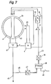
- An automatically comparing sensor device according to the invention is shown schematically in FIG.
- the means for feeding the additional excitation coil are essentially the same as in FIG. 4, with controllable resistors 18 and 19, series resistors 20 and 21 and amplifier 22.
- the input 23 of amplifier 22 is here connected to a digital / analog converter 38.
- the receiver coils 41 and 42 of the sensor system which are arranged schematically on a carrier disk 39, are located at the input of an amplifier and phase comparator 43. The latter receives a phase-appropriate signal from the HF generator 4.
- the HF generator 4 also feeds the voltage divider 18, 19 and, via the lines 25, the primary excitation coil (not shown).
- the output of the amplifier 43 leads via a line 45 to a control device which is to be guided by the sensor device.
- a connection 46 which is shown schematically as a switch and can be switched on temporarily, leads from line 45 to an analog-to-digital converter 47, which at its output provides a digital signal corresponding to the direction (polarity) and voltage level of the output signal of amplifier 43 in parallel form, which to a non-volatile memory 48.
- an analog-to-digital converter 47 which at its output provides a digital signal corresponding to the direction (polarity) and voltage level of the output signal of amplifier 43 in parallel form, which to a non-volatile memory 48.
- the value from the converter 47 is established, it is read into the memory 48 by an activation signal supplied on a line 49 and stored there in a non-volatile manner.
- the output of the memory 48 leads to the digital / analog converter 38. There the value contained in the memory is converted into a control signal for the correction coil currents.
- the sensor system is brought into a neutral position in which it is not influenced by any external electrically conductive parts.
- the output signal of amplifier 43 on line 45 changes.
- this output signal has already been fully corrected, ie has become zero. If an error signal still exists, this is activated by pressing it again tion of the switch 46 is taken back into the memory 48 and added to the previous value, and the sum is output to the converter 38.
- the error of the sensor system can be fully compensated for by repeated correction.
- the automatic correction is then switched off and is only activated again at a later point in time, which can be specified by the program, for the sensor to be checked again for symmetry.
- FIG. 7 does not show the hardware elements still required for the storage and addition. However, it does not pose a problem for the person skilled in the art to implement the described processes.
- a multi-coil sensor is shown in FIG. 8, which consists of an excitation coil 51 and a receiver coil 52 and which, in a special application which requires a curvature of the coil, is designed accordingly and additionally provided with the electronic matching option according to the invention is.
- FIG. 8 shows an HF generator 50 as an exciter oscillator, which emits an alternating current to the excitation coil 51.
- 52 represents the receiver coil. Its arrangement is similar to that of a goniometer in such a way that the partial fields of the excitation coil 52 cancel each other out in both coil halves and not, as in the previous examples, the partial voltages of two coils generated by a field.
- the receiver coil 52 is in turn equipped with a receive amplifier 53 with the phase comparator 53 a, at the output of which an output signal dependent on the field change occurs when the field in the receiver coil 52 is changed asymmetrically.
- the retuning coil which is arranged symmetrically to the excitation coil 51 and is designed as an additional excitation coil, is designated, the halves of which, as already described in the preceding examples, can be supplied with different currents in order to avoid asymmetries of the primary excitation field and / or that To compensate receiver coil 52 acting field.
- the retuning can be done manually or automatically; it can compensate for asymmetries in phase and / or amplitude.
- FIG. 9 shows another multi-coil sensor device which has a double coil in the excitation circuit instead of the excitation coil arrangement designated 51 in FIG.
- This excitation coil is designated 55. It consists of two sub-coils 55a, 55b, which are connected to one another and each generate fields that are opposite by 180 °, so that the receiver coil 52 in turn does not emit any voltage if the alignment or alignment is precise.
- the tuning coil 56 is divided into two coil halves 56a and 56b, which are assigned to the two excitation coils 55a, 55b.
- both halves 56a, 56b can in turn be operated with different excitation currents of the same frequency or with different phase positions of their currents in relation to the main excitation current in order to bring about the effect according to the invention.
- RF generator 50, amplifier 53 and phase comparator 53a are arranged as in FIG.
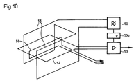
- FIG. 10 finally shows a basic sensor arrangement corresponding to FIG. 9, in which, however, only one tuning coil 56 is used, which is arranged asymmetrically with respect to the excitation field and which enables the overall field to be corrected in the manner according to the invention by phase-shifted currents relative to the excitation field.
- the excitation oscillator or HF generator is designated by 50, the two partial coils of the double excitation coil and 55 the receiver coil.
Landscapes
- Life Sciences & Earth Sciences (AREA)
- Engineering & Computer Science (AREA)
- Physics & Mathematics (AREA)
- Geophysics (AREA)
- Remote Sensing (AREA)
- General Life Sciences & Earth Sciences (AREA)
- General Physics & Mathematics (AREA)
- Environmental & Geological Engineering (AREA)
- Geology (AREA)
- Electromagnetism (AREA)
- Manufacturing & Machinery (AREA)
- Investigating Or Analyzing Materials By The Use Of Magnetic Means (AREA)
- Geophysics And Detection Of Objects (AREA)
- Measurement Of Length, Angles, Or The Like Using Electric Or Magnetic Means (AREA)
- Switches That Are Operated By Magnetic Or Electric Fields (AREA)
Priority Applications (1)
| Application Number | Priority Date | Filing Date | Title |
|---|---|---|---|
| AT88810504T ATE79962T1 (de) | 1987-07-24 | 1988-07-22 | Induktive sensoreinrichtung. |
Applications Claiming Priority (2)
| Application Number | Priority Date | Filing Date | Title |
|---|---|---|---|
| CH282987 | 1987-07-24 | ||
| CH2829/87 | 1987-07-24 |
Publications (2)
| Publication Number | Publication Date |
|---|---|
| EP0300974A1 true EP0300974A1 (fr) | 1989-01-25 |
| EP0300974B1 EP0300974B1 (fr) | 1992-08-26 |
Family
ID=4242535
Family Applications (1)
| Application Number | Title | Priority Date | Filing Date |
|---|---|---|---|
| EP88810504A Expired - Lifetime EP0300974B1 (fr) | 1987-07-24 | 1988-07-22 | Equipement de capteur inductif |
Country Status (3)
| Country | Link |
|---|---|
| EP (1) | EP0300974B1 (fr) |
| AT (1) | ATE79962T1 (fr) |
| DE (1) | DE3874040D1 (fr) |
Cited By (6)
| Publication number | Priority date | Publication date | Assignee | Title |
|---|---|---|---|---|
| WO1991003746A1 (fr) * | 1989-09-08 | 1991-03-21 | Atomic Energy Of Canada Limited | Systeme detecteur de metaux |
| EP0393387A3 (fr) * | 1989-04-19 | 1992-07-08 | INSTITUT DR. FRIEDRICH FÖRSTER PRÜFGERÄTEBAU GMBH & CO. KG | Agencement de bobines pour un appareil de détection inductive |
| DE4132651C1 (en) * | 1991-10-01 | 1992-10-08 | Messer Griesheim Gmbh, 6000 Frankfurt, De | Data monitoring device for thermal workpiece machining - has transformer for amplifying voltage of AC voltage signal, inserted between AC voltage generator and workpiece |
| DE4423661A1 (de) * | 1994-07-06 | 1996-01-11 | Foerster Inst Dr Friedrich | Suchspulenanordnung |
| DE102011086773A1 (de) * | 2011-11-22 | 2013-05-23 | Robert Bosch Gmbh | Metallsensor |
| WO2013087281A3 (fr) * | 2011-12-13 | 2013-10-10 | Robert Bosch Gmbh | Détecteur de métaux |
Citations (2)
| Publication number | Priority date | Publication date | Assignee | Title |
|---|---|---|---|---|
| US3609527A (en) * | 1969-05-26 | 1971-09-28 | James F Ellis | Noncontacting proximity gage utilizing induced eddy currents,having improved dynamic response and interference discrimination |
| US4070612A (en) * | 1976-06-02 | 1978-01-24 | Geonics Limited | Method and apparatus for measuring terrain resistivity |
-
1988
- 1988-07-22 AT AT88810504T patent/ATE79962T1/de not_active IP Right Cessation
- 1988-07-22 EP EP88810504A patent/EP0300974B1/fr not_active Expired - Lifetime
- 1988-07-22 DE DE8888810504T patent/DE3874040D1/de not_active Expired - Lifetime
Patent Citations (2)
| Publication number | Priority date | Publication date | Assignee | Title |
|---|---|---|---|---|
| US3609527A (en) * | 1969-05-26 | 1971-09-28 | James F Ellis | Noncontacting proximity gage utilizing induced eddy currents,having improved dynamic response and interference discrimination |
| US4070612A (en) * | 1976-06-02 | 1978-01-24 | Geonics Limited | Method and apparatus for measuring terrain resistivity |
Non-Patent Citations (1)
| Title |
|---|
| PATENT ABSTRACTS OF JAPAN, Band 9, Nr. 79 (P-347)[1802], 9. April 1985; & JP-A-59 210 389 (KIYOUSAN SEISAKUSHO K.K.) 29-11-1984 * |
Cited By (9)
| Publication number | Priority date | Publication date | Assignee | Title |
|---|---|---|---|---|
| EP0393387A3 (fr) * | 1989-04-19 | 1992-07-08 | INSTITUT DR. FRIEDRICH FÖRSTER PRÜFGERÄTEBAU GMBH & CO. KG | Agencement de bobines pour un appareil de détection inductive |
| WO1991003746A1 (fr) * | 1989-09-08 | 1991-03-21 | Atomic Energy Of Canada Limited | Systeme detecteur de metaux |
| AU640685B2 (en) * | 1989-09-08 | 1993-09-02 | Atomic Energy Of Canada Limited | Metal detecting system |
| DE4132651C1 (en) * | 1991-10-01 | 1992-10-08 | Messer Griesheim Gmbh, 6000 Frankfurt, De | Data monitoring device for thermal workpiece machining - has transformer for amplifying voltage of AC voltage signal, inserted between AC voltage generator and workpiece |
| DE4423661A1 (de) * | 1994-07-06 | 1996-01-11 | Foerster Inst Dr Friedrich | Suchspulenanordnung |
| DE102011086773A1 (de) * | 2011-11-22 | 2013-05-23 | Robert Bosch Gmbh | Metallsensor |
| WO2013075861A3 (fr) * | 2011-11-22 | 2013-07-18 | Robert Bosch Gmbh | Capteur métallique |
| US9638825B2 (en) | 2011-11-22 | 2017-05-02 | Robert Bosch Gmbh | Metal sensor |
| WO2013087281A3 (fr) * | 2011-12-13 | 2013-10-10 | Robert Bosch Gmbh | Détecteur de métaux |
Also Published As
| Publication number | Publication date |
|---|---|
| ATE79962T1 (de) | 1992-09-15 |
| EP0300974B1 (fr) | 1992-08-26 |
| DE3874040D1 (de) | 1992-10-01 |
Similar Documents
| Publication | Publication Date | Title |
|---|---|---|
| DE2453898B2 (de) | Vorrichtung zum Messen des Abstandes zwischen einer als Fühler dienenden Spule und einem Metallkörper | |
| EP1797463A1 (fr) | Dispositif pour la localisation d'objets metalliques et procede d'ajustement dudit dispositif | |
| DE2910491C2 (fr) | ||
| CH666359A5 (de) | Vorrichtung zur steuerung von magnetisch angetriebenen massenschwingsystemen. | |
| EP0098238B1 (fr) | Dispositif de mesure à induction respectivement capteur et application | |
| DE3732660A1 (de) | Magnetresonanz-abbildungssystem | |
| EP0300974B1 (fr) | Equipement de capteur inductif | |
| EP1207372B1 (fr) | Procédé et appareil pour le conditionnement d'un signal analogique périodique | |
| EP0050705B1 (fr) | Méthode et circuit pour mesurer sans contact des courants continus et alternatifs, en particulier des valeurs instantanées de courant | |
| DE3225166A1 (de) | Metalldetektor | |
| DE3326477A1 (de) | Anordnung zur bestimmung der drehzahl, der drehrichtung und/oder des drehwinkels eines gegenstandes | |
| EP0337939A2 (fr) | Capteur inductif et appareil de mesure pour obtenir la position relative d'un capteur | |
| DE3326476A1 (de) | Anordnung zur bestimmung der position, der geometrischen abmessungen oder der bewegungsgroessen eines gegenstandes | |
| EP0476075B1 (fr) | Circuit d'evaluation pour capteurs de position d'etrangleurs differentiels et son utilisation | |
| DE1261938C2 (de) | Schaltungsanordnung zur regelung der feldstaerke eines elektromagneten | |
| DE3313820C2 (fr) | ||
| DE2924093A1 (de) | Induktiver differentialweggeber | |
| DE102009029928A1 (de) | Metalldetektor | |
| DE102014209339B4 (de) | Induktiver Näherungsschalter | |
| DE3927833C2 (de) | Meßschaltung und Anwendung derselben, insbesondere mit induktiven Weggebern | |
| DE102014209243B4 (de) | Induktiver Näherungsschalter | |
| DE1001731B (de) | Schaltungsanordnung zur selbsttaetigen Impedanzanpassung | |
| EP0538578A1 (fr) | Capteur de courant selon le principe de la compensation | |
| DE202014105253U1 (de) | Induktiver Näherungsschalter | |
| DE1154519B (de) | Breitbandiger Transistorverstaerker mit regelbarem Verstaerkungsfaktor |
Legal Events
| Date | Code | Title | Description |
|---|---|---|---|
| PUAI | Public reference made under article 153(3) epc to a published international application that has entered the european phase |
Free format text: ORIGINAL CODE: 0009012 |
|
| AK | Designated contracting states |
Kind code of ref document: A1 Designated state(s): AT DE ES FR GB IT SE |
|
| 17P | Request for examination filed |
Effective date: 19890621 |
|
| 17Q | First examination report despatched |
Effective date: 19901002 |
|
| GRAA | (expected) grant |
Free format text: ORIGINAL CODE: 0009210 |
|
| AK | Designated contracting states |
Kind code of ref document: B1 Designated state(s): AT DE ES FR GB IT SE |
|
| PG25 | Lapsed in a contracting state [announced via postgrant information from national office to epo] |
Ref country code: IT Free format text: LAPSE BECAUSE OF FAILURE TO SUBMIT A TRANSLATION OF THE DESCRIPTION OR TO PAY THE FEE WITHIN THE PRE;WARNING: LAPSES OF ITALIAN PATENTS WITH EFFECTIVE DATE BEFORE 2007 MAY HAVE OCCURRED AT ANY TIME BEFORE 2007. THE CORRECT EFFECTIVE DATE MAY BE DIFFERENT FROM THE ONE RECORDED.SCRIBED TIME-LIMIT Effective date: 19920826 Ref country code: SE Free format text: THE PATENT HAS BEEN ANNULLED BY A DECISION OF A NATIONAL AUTHORITY Effective date: 19920826 Ref country code: ES Free format text: THE PATENT HAS BEEN ANNULLED BY A DECISION OF A NATIONAL AUTHORITY Effective date: 19920826 |
|
| REF | Corresponds to: |
Ref document number: 79962 Country of ref document: AT Date of ref document: 19920915 Kind code of ref document: T |
|
| REF | Corresponds to: |
Ref document number: 3874040 Country of ref document: DE Date of ref document: 19921001 |
|
| ET | Fr: translation filed | ||
| GBT | Gb: translation of ep patent filed (gb section 77(6)(a)/1977) | ||
| PLBE | No opposition filed within time limit |
Free format text: ORIGINAL CODE: 0009261 |
|
| STAA | Information on the status of an ep patent application or granted ep patent |
Free format text: STATUS: NO OPPOSITION FILED WITHIN TIME LIMIT |
|
| PG25 | Lapsed in a contracting state [announced via postgrant information from national office to epo] |
Ref country code: AT Effective date: 19930722 |
|
| 26N | No opposition filed | ||
| PGFP | Annual fee paid to national office [announced via postgrant information from national office to epo] |
Ref country code: GB Payment date: 19940711 Year of fee payment: 7 |
|
| PGFP | Annual fee paid to national office [announced via postgrant information from national office to epo] |
Ref country code: FR Payment date: 19940722 Year of fee payment: 7 |
|
| PG25 | Lapsed in a contracting state [announced via postgrant information from national office to epo] |
Ref country code: GB Effective date: 19950722 |
|
| GBPC | Gb: european patent ceased through non-payment of renewal fee |
Effective date: 19950722 |
|
| PG25 | Lapsed in a contracting state [announced via postgrant information from national office to epo] |
Ref country code: FR Effective date: 19960430 |
|
| REG | Reference to a national code |
Ref country code: FR Ref legal event code: ST |
|
| REG | Reference to a national code |
Ref country code: FR Ref legal event code: ST |
|
| REG | Reference to a national code |
Ref country code: FR Ref legal event code: ST |
|
| PGFP | Annual fee paid to national office [announced via postgrant information from national office to epo] |
Ref country code: DE Payment date: 19980629 Year of fee payment: 11 |
|
| PG25 | Lapsed in a contracting state [announced via postgrant information from national office to epo] |
Ref country code: DE Free format text: LAPSE BECAUSE OF NON-PAYMENT OF DUE FEES Effective date: 20000601 |