EP0301095A1 - Baguette d'apport - Google Patents
Baguette d'apport Download PDFInfo
- Publication number
- EP0301095A1 EP0301095A1 EP19870906040 EP87906040A EP0301095A1 EP 0301095 A1 EP0301095 A1 EP 0301095A1 EP 19870906040 EP19870906040 EP 19870906040 EP 87906040 A EP87906040 A EP 87906040A EP 0301095 A1 EP0301095 A1 EP 0301095A1
- Authority
- EP
- European Patent Office
- Prior art keywords
- wire
- cross
- section
- cavity
- area
- Prior art date
- Legal status (The legal status is an assumption and is not a legal conclusion. Google has not performed a legal analysis and makes no representation as to the accuracy of the status listed.)
- Withdrawn
Links
Images


Classifications
-
- B—PERFORMING OPERATIONS; TRANSPORTING
- B23—MACHINE TOOLS; METAL-WORKING NOT OTHERWISE PROVIDED FOR
- B23K—SOLDERING OR UNSOLDERING; WELDING; CLADDING OR PLATING BY SOLDERING OR WELDING; CUTTING BY APPLYING HEAT LOCALLY, e.g. FLAME CUTTING; WORKING BY LASER BEAM
- B23K35/00—Rods, electrodes, materials, or media, for use in soldering, welding, or cutting
- B23K35/02—Rods, electrodes, materials, or media, for use in soldering, welding, or cutting characterised by mechanical features, e.g. shape
- B23K35/0255—Rods, electrodes, materials, or media, for use in soldering, welding, or cutting characterised by mechanical features, e.g. shape for use in welding
- B23K35/0261—Rods, electrodes or wires
-
- B—PERFORMING OPERATIONS; TRANSPORTING
- B23—MACHINE TOOLS; METAL-WORKING NOT OTHERWISE PROVIDED FOR
- B23K—SOLDERING OR UNSOLDERING; WELDING; CLADDING OR PLATING BY SOLDERING OR WELDING; CUTTING BY APPLYING HEAT LOCALLY, e.g. FLAME CUTTING; WORKING BY LASER BEAM
- B23K35/00—Rods, electrodes, materials, or media, for use in soldering, welding, or cutting
- B23K35/02—Rods, electrodes, materials, or media, for use in soldering, welding, or cutting characterised by mechanical features, e.g. shape
- B23K35/0255—Rods, electrodes, materials, or media, for use in soldering, welding, or cutting characterised by mechanical features, e.g. shape for use in welding
- B23K35/0261—Rods, electrodes or wires
- B23K35/0266—Rods, electrodes or wires flux-cored
Definitions
- the present invention relates to the field of welding, in particular to an electrode wire which consists of a metallic carrier and of batch additives.
- Solid wires and powder wires are used as the consumable electrodes.
- the solid wire represents a similar monolithic long metal rod, while the powder wire is a composite material which consists of a thin-walled sheath of tubular or more complicated cross-section and a mixture.
- the mixture which is located in the interior formed by the powder wire sheath, represents a mechanical mixture of metal powders (iron powder, ferro alloys, alloy powder) of slag-forming and stabilizing components.
- the ratio of the cross-sectional area of the cavity in the powder wire filled with the mixture to the cross-sectional area of the entire wire is usually from 0.5 to 0.8.
- the powder wires offer the possibility of both good quality welds with high mechanical properties; the shielding gas and submerged arc welding as well as without a protective atmosphere, but they have to sub differed from the solid wires at a high price, are complicated to manufacture and require special feeders (with several pairs of wire feed rollers) which guarantee a low specific pressure on the wire surface due to the stiffness of the wire, which usually results from cold-rolled low-carbon steel from 0.2 to 0.5 mm thick is insufficient.
- Metal powders which belong to the composition of the powder wire in a mixture with slag-forming components, are exposed to corrosion, which limits the storage period of such wires, which is why the process of welding by means of the powder wire from the point of view of the formation of weld seams of high quality
- the powder wire mixture does not conduct the electrical current, despite the fact that it contains a large amount of metallic components (iron powder and ferro alloys), and therefore there is a significant lag in the melting of the wire core from the melting of the metal sheath during the welding process. Due to insufficient heating, individual batch parts pass into the weld pool without melting, which reduces the effectiveness of the slag protection of the drops of the molten metal during their growth at the front end of the electrode and the transfer to the weld pool, ie some of the slag takes on the protection of the molten material not part against air.
- the self-protection powder wires in the batch contain 15 to 20% by mass of slag-forming protective materials, which means that they have a lower welding performance compared to the solid wires.
- the main cause of the uneven melting of the batch and the metallic carrier in the powder wires is inadequate contact area of the electrically non-conductive batch with the metallic carrier of the wire and the low rate of heat propagation in the batch volume.
- the insufficiently heated molten slag has a high viscosity and does not flow well on the surface of the drops in the electrode talls, which explains the less effective slag protection of the molten metal.
- the electrode wire which consists of a metallic carrier and a mixture of the appropriate composition located in the longitudinal channels of this carrier, ensures, in contrast to the solid wires, minimal splashing and excellent shaping of the weld seams and, in contrast to the powder wires, ensures high welding performance, is not expensive, has sufficient rigidity and does not require the use of special multi-roll feed devices, the components of the mixture of such a wire not being exposed to corrosion.
- the best known wire of this construction is an electrode wire which consists of a metallic carrier and a mixture and in which in the metallic carrier there are essentially voids along the generating surface which extend onto the wire surface and each of which represents a geometrical figure in cross section, which tapers in the direction of the outer surface of the wire (GB, A, 1481140).
- the solution according to the invention comes closest to the construction of an electrode wire which is designed with at least one longitudinal cavity which is filled with a mixture and has an expanded configuration in cross section (GB, A, 686120).
- the construction of the known wire has symmetrical cross-sections, which are directed from the center to the outer surface of the wire.
- the width of the cavities in the wire cross section increases in the direction from the center to the outer surface of the wire.
- the wire contains 6 mass% or less mixture that is in the cavities.
- the wire of such a construction ensures a welding performance equal to or even higher than the solid wires in the absence of spatter and with good weld seam formation.
- this wire does not eliminate the lagging of the melt behind the melt of the metallic support due to a small contact area of the electrically non-conductive mix with the metallic support and a low rate of heat transfer from the surface of the cavity to the depth of the mix and does not adequately ensure effective slag protection of the molten drops of the electrode metal against air, which is due to incomplete melting of the mixture and transfer of some of the slag-forming components into the weld pool in the form of unmelted particles, which therefore do not participate in the formation of a slag protection film on the surface of the electrode drops.
- the present invention has for its object to provide such a wire construction, which ensure a simultaneous melting of the metallic support and the electrically non-conductive mixture located in the longitudinal spaces and the effectiveness of S chlackentikes and the molten metal drop was increased to the weld pool during their growth on the end face of the electrode and during their Uber wear.
- each longitudinal cavity has a slit-like shape in cross-section, the ratio of the width of the cavity in cross-section to its surface area being substantially between 0.005 and 0.5, while the ratio of the cross-sectional area of the cavity or the total area the cross-sections of cavities to the cross-sectional area of the wire is essentially between 0.05 and 0.5.
- the main advantage of the wire of this construction is that when the cavity is designed in the form of a narrow slot, in which the ratio of the cross-sectional width to the cross-sectional area is in the range of 0.005 to 0.5, such a contact area of the electrically non-conductive mixture with the metallic carrier and heat transfer from the metal to the batch is ensured that during the welding process the batch will heat up to the melting temperature across the entire width of the cavity. Thanks to the sufficient heating of the batch over the entire width of the cavity and the simultaneous melting of the same with the metallic carrier, the molten slag on the surface of the metal drops which form when welding at the front end of the electrode has better covering power and consequently better protective properties because it is one slightly lower viscosity due to heating to a higher temperature.
- the lower limit of the ratio of the thickness to the area of the cavity in cross section which is 0.005, is determined by the grain size composition of the batch components, the grain sizes of which are commensurable with the slot width in the present case. It is not possible to achieve a uniform distribution and a common melting of different batch components in the cavity volume with a ratio of the width of the cavity to the surface area in cross-section thereof below 0.005, which means that a wire with good welding technology characteristics is impossible to obtain.
- the ratio of the surface area of the cavity or the total area of the cross-sections of cavities to the cross-sectional area of the wire should not be less than 0.05, because in this case the positive effect of the mixture on the effectiveness of the slag protection of the molten metal of the electrode drops is hardly noticeable, the burning stability of the Arc worsens by leaps and bounds as splashing increases.
- each longitudinal cavity is located in the wire in such a way that from 0.03 to 1 of the cross-sectional area of the cavity is at a distance of at most ü. 3 of the diameter of the wire from its surface.
- This contributes to improving the heat transfer to the batch and ensures a more uniform melting of the batch with the metallic carrier, which ultimately increases the effectiveness of the metal's slag protection.
- 50% of the batch volume lies at a distance of 0.3 of the diameter from the wire surface, which is why the preferred arrangement of the batch in this volume on the one hand ensures the physical protection of the volume of the melting metallic carrier of the electrode wire, which is located in the central part of the wire cross-section.
- the peripheral areas of the metallic carrier of the wire are heated to a higher temperature in cross section than the central part thereof.
- the limitation of part of the surface area of the cavities in the peripheral area of the wire to the size 0.3 is due to the coagulation speed of the slag in the volume of the molten drop at the front end of the electrode, by the floating of the slag on the drop surface and the flow of the slag film on the drop surface .
- the effectiveness of the slag protection during the growth of the drop at the front end of the electrode proves to be insufficient, ie during the Time sufficient until the formation of the slag film
- harmful gases oxygen, hydrogen, nitrogen
- each cavity it is desirable for the width of each cavity to have a variable size in its cross section, because the surface area of the heat transfer from the metallic support to the batch is additionally increased and the reliability of the slag protection of the molten metal is thereby increased.
- the electrode wire consists of a metallic carrier and a mixture and is provided with at least one longitudinal cavity which is filled with the mixture and has an expanded configuration in cross-section.
- the cavity of the wire has a slot-shaped cross section, the ratio of the cross-sectional width to the cross-sectional area in the limits being essentially between 0.005 and 0.5, while the ratio of the cross-sectional area of the cavity to the cross-sectional area of the wire in the limits is essentially between 0.05 and 0.5.
- each longitudinal cavity in the wire is located so that from 0.3 to 1 of the cross-sectional area of the cavity at a distance of at most 0.3 of the diameter sers of the wire from its surface.
- the width of the cavity in its cross section is a variable size.
- the metallic carrier of the wire contains deoxidizing agents, while the mixture contains stabilizing and slag-forming components.
- the electrode wire shown in Fig. 1 consists of a metallic support 1 and a mixture 2, which is located in a longitudinal cavity 3, which has a developed configuration in cross section.
- the cavity 3 in cross-section is a narrow profiled slot of variable width, in which the ratio of the width of the cavity to its area in cross-section is between 0.016 and 0.5, the ratio of the area of the cavity to the area of the Wire in its cross-section is equal to 0.10 and the proportion of the area of the cavity in the cross-section, which proportion is at a distance up to 0.3 of the diameter from the wire surface 4, is 0.35.
- the metallic carrier of the wire consists of a steel that contains deoxidizers (silicon and manganese), while the mixture contains stabilizing components (potash, calcined soda) and slag-forming components (rutile concentrate, fluorite, magnesite).
- deoxidizers silicon and manganese
- stabilizing components potash, calcined soda
- slag-forming components rutile concentrate, fluorite, magnesite
- the electrode wire shown in Fig. 2 consists of a metallic carrier 5 and a mixture 6, which is located in a longitudinal cavity 7, which has an expanded configuration in cross section.
- the cross-section of the cavity 7 is a narrow, profiled slot with a bent shape, in which the ratio of the width of the cavity to its area in cross-section is 0.02, the ratio of the area of the cavity to the area of the wire in its cross-section is 0 , 11 and the proportion of the area of the cavity in cross-section, which proportion is up to 0.3 from the wire surface 8, is 0.3.
- the metallic support of the wire consists of a steel, the deox y dations- medium (silicon, manganese, aluminum), while the mixture contains stabilizing components (potash, potassium sodium silicate) and slag-forming components (rutile concentrate, quartz sand, perovskite).
- the electrode wire shown in Figure 3 consists of a metal support 9, and a mixture 10, which is located in two longitudinal cavities 11 and 12 which in cross-section a stretched - have ration - K onfig u.
- the cavities 11 and 12 are narrow, profiled slots of variable width, in which the ratio of the width of each cavity to its area in cross section is 0.008-0.12, the ratio of the area of the cavity to the area of the wire in it Cross-section is 0.05 and the proportion of the area of the cavity in cross-section, which proportion is up to 0.3 of the diameter from the wire surface 13, is 0.3.
- the metal support of the wire consists of a steel that contains deoxidizers (manganese, titanium), while the mixture contains stabilizing components (potassium-sodium-silicate, cesium carbonate) and slag-forming components (quartz sand, feldspar, cryolite, fluorite).
- the electrode wire shown in FIG. 4 consists of a metallic carrier 14 and a mixture 15, which is located in two longitudinal cavities 16 and 17, which have an expanded configuration in cross section.
- the cavities 16 and 17 are cross-sectional narrow crescent shaped slits of variable width, in which the ratio of the width of each cavity to its area is 0.005-0.15, the ratio of the area of the cavity to the area of the wire in its cross section is equal to 0.11 and the proportion of the area of the cavity in cross section, which proportion lies at a distance of up to 0.3 of the diameter from the wire surface 18, is 1.
- the metallic support of the wire consists of a steel which is a deoxidation medium (manganese), while the mixture contains a stabilizing component (calcined soda) and slag-forming components (fluorite, alumina, feldspar).
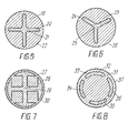
- the electrode wire shown in FIG. 5 consists of a metallic carrier 19 and a mixture 20, which is located in a longitudinal cavity 21, which has an expanded configuration in cross section.
- the cross-section of the cavity 21 is a narrow, profiled cross-shaped slot, in which the ratio of the width of the cavity to its area in cross-section is 0.014, the ratio of the area of the cavity to the area of the wire in its cross-section is 0.15 and the proportion of the area of the cavity in cross-section, which proportion lies at a distance of up to 0.3 of the diameter from the wire surface 22, is 0.4.
- the metallic support of the wire consists of a steel that contains deoxidizers (silicon and manganese), while the mixture contains a stabilizing component (sodium-potassium-silicate) and slag-forming components (rutile, cryolite, feldspar, sodium hexafluorosilicate).
- deoxidizers silicon and manganese
- stabilizing component sodium-potassium-silicate
- slag-forming components rutile, cryolite, feldspar, sodium hexafluorosilicate
- the electrode wire shown in FIG. 6 consists of a metallic carrier 23 and a mixture 24, which is located in a longitudinal cavity 25, which has an expanded configuration in cross section.
- the cross section of the cavity is a narrow, profiled slot in the form of a three-leaf plate, in which the ratio of the width of the cavity to its area in cross section is 0.018, the ratio of the area of the cavity to the area of the wire in cross section is 0, 12 and the proportion of the area of the cavity in cross section, which proportion lies at a distance of up to 0.3 of the diameter from the wire surface 26, is 0.4.
- the metallic support of the wire consists of a steel, the deoxidizing agent (silicon, manganese, Contains titanium, vanadium, aluminum), while the mixture contains a stabilizing component (cesium chromate) and slag-forming components (marble, perovskite, wollastonics, sodium hexafluorosilicate).
- the deoxidizing agent silicon, manganese, Contains titanium, vanadium, aluminum
- the mixture contains a stabilizing component (cesium chromate) and slag-forming components (marble, perovskite, wollastonics, sodium hexafluorosilicate).
- the electrode wire shown in FIG. 7 consists of a metallic carrier 27 and a mixture 28 which is located in a longitudinal cavity 29 which has an expanded configuration in cross section.
- the cross-section of the cavity is a narrow, profiled cross-shaped slot, in which the tips of the cross form segmental cavities on the wire surface 30.
- the ratio of the width of the cavity to its area in cross section is 0.02
- the ratio of the area of the cavity to the area of the wire in its cross section is equal to 0.5
- the proportion of the area of the cavity in cross section which proportion at a distance to to 0.3 of the diameter from the wire surface 30 is 0.7.
- the metallic support of the wire consists of a steel that contains deoxidizing agents (manganese, aluminum, calcium), while the mixture contains a stabilizing component (sodium carbonate) and slag-forming components (magnesite, rutile, feldspar, alumina).
- each cavity in cross section represents a narrow profiled slot, the shape of which is part of a ring, for which the ratio of the width of the cavity to the total area of the cavities in the wire cross section is 0.05, the ratio of the area of the cavities to the area of the Wire in its cross section is 0.17 and the proportion of the area of the cavities in cross section, which proportion is at a distance up to 0.3 of the diameter from the wire surface 37, 1.
- the metallic support of the wire is made of a steel that contains deoxidizers (manganese, silicon, cerium, lanthanum) while the mixture contains stabilizing components (zasium dichromate, rubidium nitrate) and slag-forming components (magnesite, feldspar, manganese ore, ilmenite concentrate).
- deoxidizers manganese, silicon, cerium, lanthanum
- stabilizing components zasium dichromate, rubidium nitrate
- slag-forming components magneticsite, feldspar, manganese ore, ilmenite concentrate
- each cavity in cross section represents a narrow profiled slot, the shape of which, like in FIG. 8, is the part of a ring for which the ratio of the width of the cavity to the total area of the cavities in the wire cross section is 0.06, the ratio of The area of the cavities to the area of the wire in its cross section is 0.09 and the proportion of the area of the cavities in cross section, which is at a distance up to 0.3 of the diameter from the wire surface 43, is 1.
- the metallic support of the wire consists of a steel that contains deoxidizers (carbon, silicon, manganese, calcium, barium), while the mixture contains stabilizing components (cesium carbonate and potassium carbonate) and slag-forming components (Hutil, Fluorite, Magnesite, Feldspar).
- the electrode wire shown in FIG. 10 consists of a metallic carrier 44 and a mixture 45, which is located in a cavity 46, which has an expanded cross section.
- the cavity in cross section is a narrow profiled slot of the double-T profile, in which the ratio of the width of the cavity to its area in cross section is 0.01, the ratio of the area of the cavity to the area of the wire in it Cross-section is 0.18 and the proportion of the area of the cavity in cross-section, which proportion is at a distance up to 0.3 of the diameter from the wire surface 47, is 0.8.
- the metallic support of the wire consists of a steel that contains deoxidizers (carbon, manganese, aluminum, calcium), while the mixture contains stabilizing components (potassium carbonate and sodium carbonate) and slag-forming components Components (marble, perovskite, wollastonite, cryolite, clay) contains.
- the electrode wire shown in FIG. 11 consists of a metallic carrier 48 and a mixture 49, which is located in four cavities 50, 51, 52 and 53, which have an expanded configuration in cross section.
- the cavities represent narrow, profiled slots of V-shaped profile, in which the ratio of the width of the cavity to its area in the wire cross section is 0, u32, the ratio of the area of the cavity to the area of the wire in its cross section equal to 0 , 17 and the proportion of the surface area of the cavity in cross section, which proportion lies at a distance of up to 0.3 of the diameter from the wire surface 54, is 0.32.
- the metallic support of the wire consists of a steel that contains deoxidizers (carbon, silicon, manganese, titanium, aluminum, zirconium), while the mixture contains a stabilizing component (potassium sodium silicate) and slag-forming components (marble, perovskite, fluorite, Contains cryolite).
- deoxidizers carbon, silicon, manganese, titanium, aluminum, zirconium
- stabilizing component potassium sodium silicate
- slag-forming components marble, perovskite, fluorite, Contains cryolite
- the electrode wire shown in FIG. 12 consists of a metallic carrier 55 and a mixture 56, which is located in two cavities 57 and 58, which have an expanded configuration in cross section.
- the cross section of the cavity is a narrow, profiled slot in the form of a half ring, in which the ratio of the width of the cavity to its area in the wire cross section is 0.026, the ratio of the area of the cavity to the area of the wire in its cross section is 0, 14 and the proportion of the surface area of the cavity in cross section, which proportion lies at a distance of up to 0.3 of the diameter from the wire surface 59, is 1.
- the metallic support of the wire consists of a steel that contains deoxidizers (silicon, manganese), while the mixture contains a stabilizing component (sodium carbonate) and slag-forming components (marble, Rutile, cryolite, fluorite) contains.
- deoxidizers silicon, manganese
- stabilizing component sodium carbonate
- slag-forming components marble, Rutile, cryolite, fluorite
- the electrode wires are preferably used for welding with additional gas protection with argon, helium, carbon dioxide or mixtures thereof, including with oxygen additives, while the wires, the cross section of which are used 3, 4, 7, 8, 9, 10, can be used effectively for welding without additional protection.
- the invention can be used with the greatest success for arc welding by means of an consumable electrode in protective gases or without additional protection in the production of metal structures from low-carbon and low-alloy steels.
- the invention can be used for build-up welding and as a filler material for welding using an inedible electrode (tungsten electrode) and for soldering.
- tungsten electrode inedible electrode
Landscapes
- Engineering & Computer Science (AREA)
- Mechanical Engineering (AREA)
- Arc Welding In General (AREA)
- Nonmetallic Welding Materials (AREA)
- Nitrogen And Oxygen Or Sulfur-Condensed Heterocyclic Ring Systems (AREA)
Abstract
Une baguette d'apport destinée au soudage possède au moins une cavité longitudinale (3) ménagée dans sa base métallique (1) et remplie d'une charge (2). La cavité (3) présente une section transversale en forme de fente, le rapport entre sa largeur et sa surface se situant dans la plage 0,005 à 0,5, tandis que le rapport entre la surface de la section de la cavité (3) et celle de la baguette se situe dans la plage 0,005 à 0,5.
Applications Claiming Priority (2)
| Application Number | Priority Date | Filing Date | Title |
|---|---|---|---|
| SU4187001 | 1987-02-09 | ||
| SU4187001 | 1987-02-09 |
Publications (1)
| Publication Number | Publication Date |
|---|---|
| EP0301095A1 true EP0301095A1 (fr) | 1989-02-01 |
Family
ID=21282745
Family Applications (1)
| Application Number | Title | Priority Date | Filing Date |
|---|---|---|---|
| EP19870906040 Withdrawn EP0301095A1 (fr) | 1987-02-09 | 1987-06-19 | Baguette d'apport |
Country Status (4)
| Country | Link |
|---|---|
| EP (1) | EP0301095A1 (fr) |
| JP (1) | JPH01502651A (fr) |
| CN (1) | CN88100731A (fr) |
| WO (1) | WO1988005708A1 (fr) |
Cited By (3)
| Publication number | Priority date | Publication date | Assignee | Title |
|---|---|---|---|---|
| CN102554520A (zh) * | 2012-03-07 | 2012-07-11 | 江苏科技大学 | 一种用于水下湿式电弧切割的药芯割丝及其制备方法 |
| CN103464919A (zh) * | 2013-09-22 | 2013-12-25 | 昆山市圣翰锡业有限公司 | 一种改进型焊条 |
| EP4631650A1 (fr) * | 2024-02-23 | 2025-10-15 | Goodrich Corporation | Fils centraux à répartitions multiples avec poudres multi-matériaux pour propriétés de matériau personnalisées dans la fabrication additive à l'arc électrique (waam) |
Families Citing this family (1)
| Publication number | Priority date | Publication date | Assignee | Title |
|---|---|---|---|---|
| CN110936065A (zh) * | 2019-12-17 | 2020-03-31 | 浙江永旺焊材制造有限公司 | 新型药芯银钎料 |
Family Cites Families (3)
| Publication number | Priority date | Publication date | Assignee | Title |
|---|---|---|---|---|
| SU517441A1 (ru) * | 1974-05-28 | 1976-06-15 | Ордена Ленина И Ордена Трудового Красного Знамени Институт Электросварки Имени Е.О.Патона | Сварочна электродна проволока |
| FR2349392A1 (fr) * | 1976-04-28 | 1977-11-25 | Metaux Precieux Cie | Fil de soudage ou de brasage contenant un decapant fondant |
| SU916191A1 (ru) * | 1980-02-02 | 1982-03-30 | Inst Elektroswarki Patona | Проволока для сварки1 |
-
1987
- 1987-06-19 WO PCT/SU1987/000079 patent/WO1988005708A1/fr not_active Ceased
- 1987-06-19 JP JP62505412A patent/JPH01502651A/ja active Pending
- 1987-06-19 EP EP19870906040 patent/EP0301095A1/fr not_active Withdrawn
-
1988
- 1988-02-08 CN CN88100731A patent/CN88100731A/zh active Pending
Non-Patent Citations (1)
| Title |
|---|
| See references of WO8805708A1 * |
Cited By (4)
| Publication number | Priority date | Publication date | Assignee | Title |
|---|---|---|---|---|
| CN102554520A (zh) * | 2012-03-07 | 2012-07-11 | 江苏科技大学 | 一种用于水下湿式电弧切割的药芯割丝及其制备方法 |
| CN102554520B (zh) * | 2012-03-07 | 2013-11-06 | 江苏科技大学 | 一种用于水下湿式电弧切割的药芯割丝及其制备方法 |
| CN103464919A (zh) * | 2013-09-22 | 2013-12-25 | 昆山市圣翰锡业有限公司 | 一种改进型焊条 |
| EP4631650A1 (fr) * | 2024-02-23 | 2025-10-15 | Goodrich Corporation | Fils centraux à répartitions multiples avec poudres multi-matériaux pour propriétés de matériau personnalisées dans la fabrication additive à l'arc électrique (waam) |
Also Published As
| Publication number | Publication date |
|---|---|
| WO1988005708A1 (fr) | 1988-08-11 |
| CN88100731A (zh) | 1988-08-31 |
| JPH01502651A (ja) | 1989-09-14 |
Similar Documents
| Publication | Publication Date | Title |
|---|---|---|
| EP0417546B1 (fr) | Electrode basique à âme métallique | |
| DE69418894T2 (de) | Plasmabrenner | |
| DE2000037C3 (de) | Schmelzschweißverfahren mit abgeschirmtem Lichtbogen und mit in Schweißrichtung hintereinander angeordneten blanken, stromführenden Bandelektroden | |
| DE2521276A1 (de) | Schweisselektrode fuer das elektrische lichtbogenschweissen | |
| EP0447666A1 (fr) | Electrode basique à âme métallique et à basse teneur en hydrogène | |
| CH457652A (de) | Verfahren und Vorrichtung zum Schweissen von Gegenständen aus Metall | |
| DE2553418A1 (de) | Verfahren zum hochstrom-schutzgas- lichtbogenschweissen | |
| DE1916838C3 (de) | Kernelektrode für das Lichtbogenschweißen | |
| DE3438439A1 (de) | Pulveroberflaechenschweissverfahren | |
| DE3632466A1 (de) | Fuelldrahtelektrode und verfahren zum brennschneiden von metallen | |
| DE2534727A1 (de) | Fuelldrahtelektrode | |
| DE1758192C3 (de) | Fülldrahtelektrode zum Lichtbogenschweißen zur Abscheidung von austenitischem rostfreiem Stahl | |
| CH630547A5 (de) | Verfahren zum elektroschlackeschweissen von metallen. | |
| EP0301095A1 (fr) | Baguette d'apport | |
| DE1764116B1 (de) | Lichtbogen plasmastrahlgenerator | |
| CH357817A (de) | Elektrode | |
| DE2461774A1 (de) | Verfahren zum schweissen von aluminium und aluminiumlegierungen in horizontaler schweisslage | |
| DE2936282C2 (de) | Lichtbogenschweißverfahren | |
| DE2526259A1 (de) | Fuelldraht fuer das elektrische lichtbogenschweissen | |
| DE1558892C3 (de) | Flußmittel | |
| DE3634499A1 (de) | Lichtbogenschweisselektrode | |
| DE2012609B2 (de) | Verfahren zum einseitigen verschweissen von werkstuecken mit durchgehender schweissnaht | |
| DE4243290C1 (de) | Verfahren zur Herstellung und Regenerierung von stählernen Verschleißelementen | |
| DE2708618C3 (de) | Verfahren zum Plasma-Mehrfachlichtbogenschweißen mittels kontinuierlich brennenden Gleichstrombogen von verschiedener Polarität | |
| DE1965545C3 (de) | Verfahren und Vorrichtung zum Plasmaschweißen |
Legal Events
| Date | Code | Title | Description |
|---|---|---|---|
| PUAI | Public reference made under article 153(3) epc to a published international application that has entered the european phase |
Free format text: ORIGINAL CODE: 0009012 |
|
| 17P | Request for examination filed |
Effective date: 19881007 |
|
| AK | Designated contracting states |
Kind code of ref document: A1 Designated state(s): AT BE DE FR GB IT SE |
|
| 18W | Application withdrawn |
Withdrawal date: 19900202 |
|
| STAA | Information on the status of an ep patent application or granted ep patent |
Free format text: STATUS: THE APPLICATION HAS BEEN WITHDRAWN |
|
| R18W | Application withdrawn (corrected) |
Effective date: 19900202 |