EP0301129A2 - Paroi/plafond de filtre pour installations de technique de salle blanche - Google Patents
Paroi/plafond de filtre pour installations de technique de salle blanche Download PDFInfo
- Publication number
- EP0301129A2 EP0301129A2 EP87113890A EP87113890A EP0301129A2 EP 0301129 A2 EP0301129 A2 EP 0301129A2 EP 87113890 A EP87113890 A EP 87113890A EP 87113890 A EP87113890 A EP 87113890A EP 0301129 A2 EP0301129 A2 EP 0301129A2
- Authority
- EP
- European Patent Office
- Prior art keywords
- profile
- filter
- sealing
- ceiling
- circumferential
- Prior art date
- Legal status (The legal status is an assumption and is not a legal conclusion. Google has not performed a legal analysis and makes no representation as to the accuracy of the status listed.)
- Granted
Links
- 238000005516 engineering process Methods 0.000 title abstract description 4
- 238000009434 installation Methods 0.000 title 1
- 238000007789 sealing Methods 0.000 claims abstract description 67
- 239000000565 sealant Substances 0.000 claims abstract description 12
- 238000009826 distribution Methods 0.000 claims description 11
- 150000001875 compounds Chemical class 0.000 claims description 9
- 238000003780 insertion Methods 0.000 claims description 4
- 230000037431 insertion Effects 0.000 claims description 4
- 238000012360 testing method Methods 0.000 claims description 4
- 230000002093 peripheral effect Effects 0.000 abstract 1
- 238000013461 design Methods 0.000 description 4
- 229910000639 Spring steel Inorganic materials 0.000 description 2
- 238000010276 construction Methods 0.000 description 2
- 238000011161 development Methods 0.000 description 2
- 230000018109 developmental process Effects 0.000 description 2
- 238000012544 monitoring process Methods 0.000 description 2
- 238000004382 potting Methods 0.000 description 2
- 238000011144 upstream manufacturing Methods 0.000 description 2
- 238000009423 ventilation Methods 0.000 description 2
- XLYOFNOQVPJJNP-UHFFFAOYSA-N water Substances O XLYOFNOQVPJJNP-UHFFFAOYSA-N 0.000 description 2
- 241001295925 Gegenes Species 0.000 description 1
- 230000005540 biological transmission Effects 0.000 description 1
- 230000015572 biosynthetic process Effects 0.000 description 1
- 230000006835 compression Effects 0.000 description 1
- 238000007906 compression Methods 0.000 description 1
- 238000011109 contamination Methods 0.000 description 1
- 238000006073 displacement reaction Methods 0.000 description 1
- 238000001914 filtration Methods 0.000 description 1
- 239000007788 liquid Substances 0.000 description 1
- 238000012423 maintenance Methods 0.000 description 1
- 230000007257 malfunction Effects 0.000 description 1
- 238000004519 manufacturing process Methods 0.000 description 1
- 239000000463 material Substances 0.000 description 1
- 239000002184 metal Substances 0.000 description 1
- 230000008520 organization Effects 0.000 description 1
- 239000002245 particle Substances 0.000 description 1
- 238000003825 pressing Methods 0.000 description 1
- 239000003566 sealing material Substances 0.000 description 1
- 230000006641 stabilisation Effects 0.000 description 1
- 238000011105 stabilization Methods 0.000 description 1
- 239000000725 suspension Substances 0.000 description 1
- 238000012549 training Methods 0.000 description 1
Images



Classifications
-
- E—FIXED CONSTRUCTIONS
- E04—BUILDING
- E04B—GENERAL BUILDING CONSTRUCTIONS; WALLS, e.g. PARTITIONS; ROOFS; FLOORS; CEILINGS; INSULATION OR OTHER PROTECTION OF BUILDINGS
- E04B9/00—Ceilings; Construction of ceilings, e.g. false ceilings; Ceiling construction with regard to insulation
- E04B9/06—Ceilings; Construction of ceilings, e.g. false ceilings; Ceiling construction with regard to insulation characterised by constructional features of the supporting construction, e.g. cross section or material of framework members
- E04B9/064—Ceilings; Construction of ceilings, e.g. false ceilings; Ceiling construction with regard to insulation characterised by constructional features of the supporting construction, e.g. cross section or material of framework members comprising extruded supporting beams
-
- E—FIXED CONSTRUCTIONS
- E04—BUILDING
- E04B—GENERAL BUILDING CONSTRUCTIONS; WALLS, e.g. PARTITIONS; ROOFS; FLOORS; CEILINGS; INSULATION OR OTHER PROTECTION OF BUILDINGS
- E04B9/00—Ceilings; Construction of ceilings, e.g. false ceilings; Ceiling construction with regard to insulation
- E04B9/02—Ceilings; Construction of ceilings, e.g. false ceilings; Ceiling construction with regard to insulation having means for ventilation or vapour discharge
-
- E—FIXED CONSTRUCTIONS
- E04—BUILDING
- E04B—GENERAL BUILDING CONSTRUCTIONS; WALLS, e.g. PARTITIONS; ROOFS; FLOORS; CEILINGS; INSULATION OR OTHER PROTECTION OF BUILDINGS
- E04B9/00—Ceilings; Construction of ceilings, e.g. false ceilings; Ceiling construction with regard to insulation
- E04B9/22—Connection of slabs, panels, sheets or the like to the supporting construction
- E04B9/24—Connection of slabs, panels, sheets or the like to the supporting construction with the slabs, panels, sheets or the like positioned on the upperside of, or held against the underside of the horizontal flanges of the supporting construction or accessory means connected thereto
- E04B9/241—Connection of slabs, panels, sheets or the like to the supporting construction with the slabs, panels, sheets or the like positioned on the upperside of, or held against the underside of the horizontal flanges of the supporting construction or accessory means connected thereto with the slabs, panels, sheets or the like positioned on the upperside of the horizontal flanges of the supporting construction
Definitions
- the invention relates to a filter wall / ceiling for clean room systems, with filter cells inserted into a framework composed of carrier profiles, each of the filter cells being provided with a circumferential filter cell frame, in each of which a filter pack with sealing compound is inserted, the carrier profiles of the framework being sealed are essentially designed as T-profiles, the flanges of which form the supports for the filter cells as sealing flanges and which are firmly attached to the standing or hanging bolts via their webs, which are in particular designed as hollow chamber profiles
- the wall or ceiling of a clean room can be connected, tensioning means supported against the bolts being provided on the bolts, the free ends of which, acting on the filter cell frame, press the filter cells against the sealing flanges and sealing means being arranged between the sealing flanges and the cell filter frame.
- the filter cells generally have a circumferential standing flange which plunges into a channel filled with liquid or elastic sealants at the edge of the profile sections and thus produces the tightness.
- a hollow chamber is formed, into which air flows in and out in an uncontrolled manner, whereby this air from the air supply in the dead zone can now accumulate in the working area of the clean room, so that there is a certain probability of this due to the flow disturbance caused by the seal there is that disturbing particles get into the air flow.
- the object of the invention is to further develop the construction in such a way that such cavities are avoided and the connection of the filter cells to the working area of the clean room is “bumpless”.
- the formation of the filter cell frame from individual profile sections with a trough-shaped depression and projections arranged on both sides of it ensures that the filter pack with sealing compound is properly attached to the filter cell frame, so that lateral leakages are avoided.
- the outside of the sealant side of the wall which extends at right angles to the side profile section and forms the trough-shaped depression forms the counter flange for the sealing flange of the support profile of the framework.
- a circumferential sealing profile is arranged between the two, either on the sealing flange or on the part of the cell frame forming the counter flange. It goes without saying that this circumferential sealing profile can be fixed there.
- the gap between the filter cell and the carrier profiles of the lattice work holding the filter cell is bridged and thus closed by the protrusion on the side of the sealant on the profile sections of the filter cell frame. Since this projection should at most be equal to the thickness of the sealing profile, it is also ensured that the sealing profile rests on both sides and thus seals. A slight undersize of this extension allows pressing the Sealing profile, the size of the undersize depending on the rigidity or the elastic deformability of the sealing material, so that the compression until the gap closes causes a sufficient deformation of the sealing profile for sealing.
- air inlet and distribution hoods are used, the profile extensions on the clamping device side being provided with support strips for them.
- the air distribution hood having a flange which is screwed to the web and which, for better sealing, may also have a sealing compound or sealing compound applied.
- hood it is also possible to create different climatic zones within the working area of the clean room, or to comply with other ventilation conditions, whereby the hoods assigned to these special areas are supplied with correspondingly specially prepared air, which is supplied to the air inlet port of these hoods, for example via flexible pipes .
- Coil springs are used to press the filter cells, which are provided on the studs or suspension bolts that are used to fasten the framework to the wall or ceiling of the clean room.
- the bolts designed as threaded bolts have a nut with an abutment washer, which serves as an abutment for a helical spring, the other end of the helical spring acting on a tension bridge, which in turn presses on the standing edges of the extensions of the filter cells on the clamping means side.
- This tension bridge ensures uniform force transmission into two filter cells lying next to one another, these tensioning means on the narrow and on the The long sides can be provided in different numbers.
- Two clamping elements are generally sufficient for the narrow side of a filter cell. It goes without saying that for the filter cells arranged at the edge of the filter wall / ceiling, an appropriate relining must be provided for the tensioning bridge, so that the tensioning bridge also finds an abutment on both sides in this position.
- guide and clamping inserts are provided on the webs of the support profiles in connection with the clamping means, the width of which corresponds to the distance between the outer surfaces of the extensions on the clamping means side of two adjacent filter cells. This prevents canting from the outset and ensures that the counter flange to the sealing flange of the carrier profile is correctly placed on the circumferential sealing profile (or vice versa!).
- a bend provided at the free ends of the guiding and clamping insert facilitates the insertion of the filter cell if the guiding and clamping insert is designed as a spring insert made of corresponding spring steel, which protrudes somewhat further outwards in the idle state and is compressed to the distance dimension only when the filter cell is inserted becomes.
- the circumferential sealing profile can be a round cord seal, but it is also advantageous to provide two round cord seals arranged at a distance from one another.
- a U-profile can be provided, with a U open to the opposite flange. In the latter two cases, there is a circumferential space between the two round cord seals or between the two legs of the U, which can be used as a test groove.
- test grooves are used for over Testing the tightness of a sealing seat, whereby the space of the circumferential groove is placed under positive or negative pressure and the change in pressure is observed as a measure of the leak. A connection to the outside enables this pressure monitoring.
- the cross legs of the T-profile can have a slot in the area of the web on the sealant side for all or some of the support profiles of the framework, which opens the lowermost hollow chamber of the web to the outside.
- the flow disturbances can be minimized if flow-guiding bodies on the outflow side are provided, for example as flashing hoods for fluorescent tubes. Slots that are not required can be provided with a cover in order to avoid cavities that are open towards the pure work area.
- the insert can be provided with a profile pointing into the flow area, which triangular, oval, advantageously pointed-oval design fills the dead water areas of the frame profiles.
- the length of these flow guide profiles reaching into the clean room area is advantageously kept in the range of three times the base width. This length corresponds to the length of the dead water area that forms behind the support profiles of the framework under the usual malfunction conditions in the clean room.
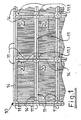
- Figures 1 and 2 show a corner section of the ceiling in supervision, with Fig. 1 the air outlet side as the outflow side, and Fig. 2 the air inlet side as the inflow side.
- a framework (10) with openings corresponding to the size of the filter cells (20) is formed from sections of the carrier profiles (11) which are joined together with connecting pieces (11.1) (two-armed for the corner connectors, three-armed for the edge connectors and four-armed for inner connectors) is.
- the filter cells (20) are inserted into the rectangular spaces thus created.
- the carrier profiles (11) are designed as T-profiles, the web (12) advantageously (Fig. 8) of the carrier profiles with continuous hollow chambers (12.1, 12.2 and 12.3) (Fig. 8) is provided and the flange (13) (Fig.
- This flange (13) (Fig. 8) is provided with a slot (14) which continues in the connecting pieces (11.1) and which is used for attaching lighting fixtures, supply devices for electrical current, compressed air or other media.
- stones provided with a threaded hole or a bolt are inserted into the lower hollow chamber (12.3) (Fig. 8) opened by the slot (14), which they can do, for example, by crossing the slots (14) in the four-armed connecting pieces (11.1) can be easily accomplished.
- the framework (10) can be connected to studs or hanging bolts (16) with the wall or ceiling of the clean room supporting the framework (10), these bolts (16), the tensioning device provided with tensioning bridges (19) for tight insertion of the Filter cells (20) are provided.
- the tensioning bridges (19) are each supported on two opposite filter cells (20), it goes without saying that in the case of marginal connecting bridges (19) this support must be produced by means of appropriate inserts (19.1).
- the filter cells (20) - the filter cells are shown as pleated filters, the position of the pleats being shown by the parallel lines - their upstream side is freely accessible, forming the space between the filter wall / ceiling and the wall or ceiling of the clean room a pressure chamber for the supply air.
- the filter cells are provided with air supply and distribution hoods (27) which can be connected to a ventilation center via the mares (28) (not shown in more detail).
- the filter folds of the filter cells can be seen through the air inlet connection (28) of the hoods (27).
- the filter cells can have different amounts of air per Unit of time and / or differently prepared air are supplied.
- the outflow sides of the filter cells are, regardless of the design and the supply air routing on the inflow side, uniformly free and allow the supply air to escape over the entire filter surface.
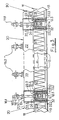
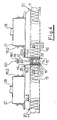
- FIGS 3 and 4 show a cross section through the filter wall / ceiling in the cutout
- Fig. 3 shows the design of the filter wall / ceiling for free inflow
- Fig. 4 shows the design of the filter wall / ceiling for an air supply via air supply and distribution hoods clarify.
- the filter cells (20), which are tightened and sealed with the aid of a tensioning device provided on the T-shaped support profiles (11), are accommodated in the support structure assembled from support profiles (11), with the aid of the connecting pieces (11.1) (Fig. 1) will.
- the T-shaped support profiles (11) consist of a web (12) which is designed as a hollow chamber profile and a flange (13), the parts of which face outwards form the sealing flange for sealing the filter cells (20) against the supporting structure.
- the bolts (16) (16.1 for the cut carrier profiles, 16.2 for the carrier profiles running transversely thereto) are fastened to the webs (12), with the webs (12) being designed as hollow chamber profiles, the simple fastening possibility being provided in that the bolt (16 ) through a hole (15) (FIG. 8) provided in the end wall of the web (12) and fixed there with the two nuts (16.3 and 16.4).
- the uppermost chamber (12.1) (Fig. 8) of the hollow chamber profile receives one of the two nuts.
- a spring (17) provided on the bolt which can be tensioned between an abutment plate (18) and a tension bridge (19) with the aid of the nut (18.1), acts on the upstanding ends (22.3) of the surrounding frame via the tension bridge (19) (22) of the filter cell (20).
- the one there force exerted on the extensions (22.3) on the clamping device side is transmitted and ultimately presses the sealing surface (22.5) (FIG. 6) of the filter cell (20) against the seals (32), which are shown here as a double-round cord seal.
- a guide and clamping insert (26) ensures the correct alignment of the filter cells (20) used.
- the filter cells (20) are assembled from side profile sections (22), the side profiles (22) having a circumferential trough-like depression (22.1) (FIG. 6), into which the filter pack (23) is inserted and with potting compound (24) ( Fig. 5) is cemented and sealed.
- FIGS. 6 and 7 show a further development of the sealing arrangement in the region of the sealing flange (13) of the carrier profile (11) formed from the web (12) and sealing flange (13) (FIG. 3).
- the trough-like depression (22.1) can be seen, which is molded into the side profiles (22) of the surrounding cell frame and into which the filter pack (23) (FIG. 5) is inserted and with sealing compound (24) (Fig. 5) is cemented in this position and sealed.
- the (in the illustration lower) outside of this trough-like recess forms the counter surface (22.5) to the sealing flange (13) and interacts with it with the interposition of the seal (32), a double round cord seal or (33) a profile seal provided with two sealing tips. Due to the pressure that the spring (17) of the tensioning device transmits to the cell frame (22), the two base line rings of the double round line ring seal (32) or the two advantageously beveled sealing lips of the profile seal (33) are pressed together, thereby producing the seal. The space between the two sealing rings of the double round cord seal (32) or between the two sealing lips of the profile seal (33) can advantageously be used to check the sealing seat.
- a line (35) is provided for pressure maintenance and monitoring, which is connected to the intermediate space via bores (34). This can be done in the simplest way - as shown in Fig. 6 - through the sealing flange (13).
- the hollow chamber profile - advantageously an extruded light metal profile - is provided in the area of the sealing flange (13) with further chambers which take over the function of the connecting line (35).
- the profile seal (33) is then applied directly to the sealing flange (13), the sealing flange (13) projecting by at least the thickness of the extensions (22.2) on the sealant side. This projection ensures that the cell frame (22) with its sealant-side extensions (22.2) is applied to the outer end of the sealing flange (13) without jolts.
- the bore (34) goes from the inner space of the profile seal (33) to the continuous hollow chamber serving as a collecting channel (35), which is provided in the region of the hollow chamber (12.3) (lowest in the illustration in FIG. 7).
- the function of this hollow chamber (12.3) is not hindered, the fastening stones that can be inserted into the hollow chamber (12.3) and are provided with threaded holes or with threaded bolts can still be inserted and as fastening elements use for suspended facilities.
- Fig. 8 is finally again a cross section through the support profile with web (12) and sealing flange (13), the chamber (12.1), the outside of which is provided with the hole (15), for receiving the fastening means for the Carrier profiles on the wall or ceiling of a clean room is used and the chamber (12.3), which is open to the outside via the sealing flange (13) provided slot (14), serves to fasten additional means.
- the chambers (12.2) arranged between serve essentially for stabilization, but they can also accommodate the connecting means for the connecting arms of the connecting pieces (11.1) (Fig. 1) and introduce the tensile forces transmitted with them into the carrier profile.
- the guide and clamping inserts (26) are used to position the filter cells (20) (Fig. 1) inserted in the supporting structure (10) (Fig.
- inserts can be designed as flow guide bodies, corresponding to FIG. 9. This training is in the Able to reduce the flow disturbances through the latticework of the support profiles (11) (Fig. 1) of the framework (10) (Fig.1) and to ensure an improvement in the homogeneity of the air distribution.
- These inserts (36) are clipped into the slots (14) with gripping heads (36.1) and form a kind of "diffuser" for each filter cell and thus ensure the trouble-free expansion of the flow. It goes without saying that these inserts (36) can also be used for secondary tasks. If a leak-proof material is used to produce these inserts (36), lighting means, advantageously fluorescent tubes, can be accommodated in these inserts for general room lighting. The heat released by these illuminants can be dissipated to the outside through ventilation to which the hollow profiles of these inserts are connected.
Landscapes
- Engineering & Computer Science (AREA)
- Architecture (AREA)
- Physics & Mathematics (AREA)
- Electromagnetism (AREA)
- Civil Engineering (AREA)
- Structural Engineering (AREA)
- Filtering Of Dispersed Particles In Gases (AREA)
- Ventilation (AREA)
- Filtering Materials (AREA)
Priority Applications (1)
| Application Number | Priority Date | Filing Date | Title |
|---|---|---|---|
| AT87113890T ATE66733T1 (de) | 1987-07-28 | 1987-09-23 | Filterwand/-decke fuer reinraumtechnische anlagen. |
Applications Claiming Priority (2)
| Application Number | Priority Date | Filing Date | Title |
|---|---|---|---|
| DE8710286U | 1987-07-28 | ||
| DE8710286U DE8710286U1 (de) | 1987-07-28 | 1987-07-28 | Filterwand/-decke für reinraumtechnische Anlagen |
Publications (3)
| Publication Number | Publication Date |
|---|---|
| EP0301129A2 true EP0301129A2 (fr) | 1989-02-01 |
| EP0301129A3 EP0301129A3 (en) | 1990-06-20 |
| EP0301129B1 EP0301129B1 (fr) | 1991-08-28 |
Family
ID=6810501
Family Applications (1)
| Application Number | Title | Priority Date | Filing Date |
|---|---|---|---|
| EP87113890A Expired - Lifetime EP0301129B1 (fr) | 1987-07-28 | 1987-09-23 | Paroi/plafond de filtre pour installations de technique de salle blanche |
Country Status (5)
| Country | Link |
|---|---|
| EP (1) | EP0301129B1 (fr) |
| AT (1) | ATE66733T1 (fr) |
| DE (2) | DE8710286U1 (fr) |
| ES (1) | ES2025607T3 (fr) |
| GR (1) | GR3003091T3 (fr) |
Cited By (6)
| Publication number | Priority date | Publication date | Assignee | Title |
|---|---|---|---|---|
| DE3926648A1 (de) * | 1989-08-11 | 1991-02-14 | Kessler & Luch Gmbh | Lueftungsdecke bzw. -wand |
| EP0627532A1 (fr) * | 1993-05-28 | 1994-12-07 | CLESTRA CLEANROOM, Société Anonyme | Nouveau système de plafond suspensu pour salle blanche |
| CN1318122C (zh) * | 2002-05-15 | 2007-05-30 | 卡尔弗罗伊登柏格两合公司 | 用于净化气体的盒式过滤器 |
| DE102014113059A1 (de) * | 2014-09-10 | 2016-03-10 | Schilling Engineering GmbH | Deckenprofil |
| DE102015118336A1 (de) * | 2015-10-27 | 2017-04-27 | Schilling Engineering GmbH | Deckensystem |
| CN107781958A (zh) * | 2017-11-06 | 2018-03-09 | 珠海格力电器股份有限公司 | 风道组件及空气净化器 |
Families Citing this family (4)
| Publication number | Priority date | Publication date | Assignee | Title |
|---|---|---|---|---|
| DE3836147C2 (de) * | 1988-10-23 | 1996-03-21 | Ltg Lufttechnische Gmbh | Reinraumdecke |
| NL9101336A (nl) * | 1991-08-02 | 1993-03-01 | Aaf Int Bv | Plafondsysteem. |
| DE4337269C1 (de) * | 1993-11-02 | 1995-04-06 | Schulz Lufttechnik Gmbh | Filterwand oder -decke für reinraumtechnische Anlagen |
| DE102009031325B4 (de) * | 2009-06-30 | 2015-04-02 | Al-Ko Therm Gmbh | Filterwand für raumlufttechnische Anlagen in Gebäuden |
Family Cites Families (4)
| Publication number | Priority date | Publication date | Assignee | Title |
|---|---|---|---|---|
| CH577664A5 (fr) * | 1974-02-15 | 1976-07-15 | Luwa Ag | |
| DE3447901C2 (de) * | 1984-12-28 | 1994-07-07 | Flaekt Ab | Von der Decke eines Raumes abhängbare modulare Rahmenanordnung zur Aufnahme von Filtern mit Fluiddichtung für Reinraumdecken |
| AU584421B2 (en) * | 1985-05-14 | 1989-05-25 | Flanders Filters Inc. | Laminar flow clean room having improved filter bank |
| DE8700927U1 (de) * | 1987-01-21 | 1987-07-09 | Weiss Klimatechnik GmbH, 6301 Reiskirchen | Einbau-Reinraumteiler für Decken- oder Wandaufbau |
-
1987
- 1987-07-28 DE DE8710286U patent/DE8710286U1/de not_active Expired
- 1987-09-23 EP EP87113890A patent/EP0301129B1/fr not_active Expired - Lifetime
- 1987-09-23 DE DE8787113890T patent/DE3772569D1/de not_active Expired - Fee Related
- 1987-09-23 ES ES198787113890T patent/ES2025607T3/es not_active Expired - Lifetime
- 1987-09-23 AT AT87113890T patent/ATE66733T1/de not_active IP Right Cessation
-
1991
- 1991-11-07 GR GR91401703T patent/GR3003091T3/el unknown
Cited By (8)
| Publication number | Priority date | Publication date | Assignee | Title |
|---|---|---|---|---|
| DE3926648A1 (de) * | 1989-08-11 | 1991-02-14 | Kessler & Luch Gmbh | Lueftungsdecke bzw. -wand |
| EP0627532A1 (fr) * | 1993-05-28 | 1994-12-07 | CLESTRA CLEANROOM, Société Anonyme | Nouveau système de plafond suspensu pour salle blanche |
| CN1318122C (zh) * | 2002-05-15 | 2007-05-30 | 卡尔弗罗伊登柏格两合公司 | 用于净化气体的盒式过滤器 |
| US7507271B2 (en) | 2002-05-15 | 2009-03-24 | Carl Freudenberg Kg | Cartridge filter for purifying gas |
| DE102014113059A1 (de) * | 2014-09-10 | 2016-03-10 | Schilling Engineering GmbH | Deckenprofil |
| DE102015118336A1 (de) * | 2015-10-27 | 2017-04-27 | Schilling Engineering GmbH | Deckensystem |
| CN107781958A (zh) * | 2017-11-06 | 2018-03-09 | 珠海格力电器股份有限公司 | 风道组件及空气净化器 |
| CN107781958B (zh) * | 2017-11-06 | 2023-08-08 | 珠海格力电器股份有限公司 | 风道组件及空气净化器 |
Also Published As
| Publication number | Publication date |
|---|---|
| ATE66733T1 (de) | 1991-09-15 |
| GR3003091T3 (en) | 1993-02-17 |
| ES2025607T3 (es) | 1992-04-01 |
| DE3772569D1 (de) | 1991-10-02 |
| EP0301129A3 (en) | 1990-06-20 |
| EP0301129B1 (fr) | 1991-08-28 |
| DE8710286U1 (de) | 1988-08-25 |
Similar Documents
| Publication | Publication Date | Title |
|---|---|---|
| DE69611163T2 (de) | Modulares luftreinigungssystem | |
| EP0187321B1 (fr) | Encadrement d'assemblage modulaire suspendu au plafond d'un local pour le logement des filtres à joints fluidiques pour des plafonds des salles blanches | |
| DE7538723U (de) | Steuereinrichtung fuer die luftstroemung eines raumes, insbesondere eines sauberraumes | |
| DE3802309C2 (fr) | ||
| EP0301129B1 (fr) | Paroi/plafond de filtre pour installations de technique de salle blanche | |
| DE69615315T2 (de) | Anordnung von lateralen elementen für ein laterales unterabfluss-system | |
| EP0355517B1 (fr) | Dispositif pour provoquer un écoulement laminaire | |
| DE2941996A1 (de) | Verfahren und vorrichtung zum verteilen von stroemungsmedien | |
| DE19905674C1 (de) | Filterpresse mit horizontal angeordneten Filterplatten | |
| DE69231211T2 (de) | Hängedeckenbauweise für einen Reinraum | |
| EP0573906B1 (fr) | Dispositif de nettoyage pour salles stériles | |
| DE3330132C2 (fr) | ||
| DE102007046891B4 (de) | Filtermodul und modulares Filtersystem | |
| DE10221375A1 (de) | Dichtungsanordnung für eine Wärmerückgewinnungszelle | |
| DE3510860A1 (de) | Kabinenkonstruktion | |
| DE202007013656U1 (de) | Filtermodul und modulares Filtersystem | |
| DE69736477T2 (de) | Luftfiltersystem für reinraum mit selbsttragenden filtereinheiten | |
| DE19709823C2 (de) | Modulsystem für Zwischendeckenkonstruktionen | |
| DE3817477A1 (de) | Filtereinheit mit filteraufnahme und filterzelle | |
| DE4337269C1 (de) | Filterwand oder -decke für reinraumtechnische Anlagen | |
| DE3727509C2 (de) | Filterrahmen-Gitterwerk | |
| DE102020121041A1 (de) | Anschlussprofil | |
| EP0418652B1 (fr) | Dispositif d'aération | |
| EP0601526A2 (fr) | Collecteur solaire | |
| EP1957179B1 (fr) | Profile specifique conçu pour des modules soufflante/filtre de construction legere |
Legal Events
| Date | Code | Title | Description |
|---|---|---|---|
| PUAI | Public reference made under article 153(3) epc to a published international application that has entered the european phase |
Free format text: ORIGINAL CODE: 0009012 |
|
| AK | Designated contracting states |
Kind code of ref document: A2 Designated state(s): AT BE CH DE ES FR GB GR IT LI LU NL SE |
|
| PUAL | Search report despatched |
Free format text: ORIGINAL CODE: 0009013 |
|
| AK | Designated contracting states |
Kind code of ref document: A3 Designated state(s): AT BE CH DE ES FR GB GR IT LI LU NL SE |
|
| 17P | Request for examination filed |
Effective date: 19900907 |
|
| 17Q | First examination report despatched |
Effective date: 19910205 |
|
| GRAA | (expected) grant |
Free format text: ORIGINAL CODE: 0009210 |
|
| AK | Designated contracting states |
Kind code of ref document: B1 Designated state(s): AT BE CH DE ES FR GB GR IT LI LU NL SE |
|
| REF | Corresponds to: |
Ref document number: 66733 Country of ref document: AT Date of ref document: 19910915 Kind code of ref document: T |
|
| REF | Corresponds to: |
Ref document number: 3772569 Country of ref document: DE Date of ref document: 19911002 |
|
| ET | Fr: translation filed | ||
| ITF | It: translation for a ep patent filed | ||
| GBT | Gb: translation of ep patent filed (gb section 77(6)(a)/1977) | ||
| REG | Reference to a national code |
Ref country code: ES Ref legal event code: FG2A Ref document number: 2025607 Country of ref document: ES Kind code of ref document: T3 |
|
| PLBE | No opposition filed within time limit |
Free format text: ORIGINAL CODE: 0009261 |
|
| STAA | Information on the status of an ep patent application or granted ep patent |
Free format text: STATUS: NO OPPOSITION FILED WITHIN TIME LIMIT |
|
| 26N | No opposition filed | ||
| REG | Reference to a national code |
Ref country code: GR Ref legal event code: FG4A Free format text: 3003091 |
|
| PGFP | Annual fee paid to national office [announced via postgrant information from national office to epo] |
Ref country code: FR Payment date: 19930812 Year of fee payment: 7 Ref country code: CH Payment date: 19930812 Year of fee payment: 7 |
|
| PGFP | Annual fee paid to national office [announced via postgrant information from national office to epo] |
Ref country code: BE Payment date: 19930813 Year of fee payment: 7 |
|
| PGFP | Annual fee paid to national office [announced via postgrant information from national office to epo] |
Ref country code: GB Payment date: 19930816 Year of fee payment: 7 |
|
| PGFP | Annual fee paid to national office [announced via postgrant information from national office to epo] |
Ref country code: SE Payment date: 19930817 Year of fee payment: 7 |
|
| PGFP | Annual fee paid to national office [announced via postgrant information from national office to epo] |
Ref country code: LU Payment date: 19930819 Year of fee payment: 7 |
|
| PGFP | Annual fee paid to national office [announced via postgrant information from national office to epo] |
Ref country code: AT Payment date: 19930820 Year of fee payment: 7 |
|
| PGFP | Annual fee paid to national office [announced via postgrant information from national office to epo] |
Ref country code: GR Payment date: 19930831 Year of fee payment: 7 |
|
| PGFP | Annual fee paid to national office [announced via postgrant information from national office to epo] |
Ref country code: ES Payment date: 19930917 Year of fee payment: 7 |
|
| PGFP | Annual fee paid to national office [announced via postgrant information from national office to epo] |
Ref country code: NL Payment date: 19930930 Year of fee payment: 7 |
|
| EPTA | Lu: last paid annual fee | ||
| PG25 | Lapsed in a contracting state [announced via postgrant information from national office to epo] |
Ref country code: LU Free format text: LAPSE BECAUSE OF NON-PAYMENT OF DUE FEES Effective date: 19940923 Ref country code: GB Effective date: 19940923 Ref country code: AT Effective date: 19940923 |
|
| PG25 | Lapsed in a contracting state [announced via postgrant information from national office to epo] |
Ref country code: SE Effective date: 19940924 Ref country code: ES Free format text: LAPSE BECAUSE OF EXPIRATION OF PROTECTION Effective date: 19940924 |
|
| PG25 | Lapsed in a contracting state [announced via postgrant information from national office to epo] |
Ref country code: LI Effective date: 19940930 Ref country code: CH Effective date: 19940930 Ref country code: BE Effective date: 19940930 |
|
| EAL | Se: european patent in force in sweden |
Ref document number: 87113890.5 |
|
| BERE | Be: lapsed |
Owner name: KESSLER & LUCH G.M.B.H. Effective date: 19940930 |
|
| PG25 | Lapsed in a contracting state [announced via postgrant information from national office to epo] |
Ref country code: GR Free format text: THE PATENT HAS BEEN ANNULLED BY A DECISION OF A NATIONAL AUTHORITY Effective date: 19950331 |
|
| PG25 | Lapsed in a contracting state [announced via postgrant information from national office to epo] |
Ref country code: NL Effective date: 19950401 |
|
| NLV4 | Nl: lapsed or anulled due to non-payment of the annual fee | ||
| GBPC | Gb: european patent ceased through non-payment of renewal fee |
Effective date: 19940923 |
|
| PG25 | Lapsed in a contracting state [announced via postgrant information from national office to epo] |
Ref country code: FR Effective date: 19950531 |
|
| REG | Reference to a national code |
Ref country code: CH Ref legal event code: PL Ref country code: GR Ref legal event code: MM2A Free format text: 3003091 |
|
| EUG | Se: european patent has lapsed |
Ref document number: 87113890.5 |
|
| REG | Reference to a national code |
Ref country code: FR Ref legal event code: ST |
|
| PGFP | Annual fee paid to national office [announced via postgrant information from national office to epo] |
Ref country code: DE Payment date: 19970916 Year of fee payment: 11 |
|
| PG25 | Lapsed in a contracting state [announced via postgrant information from national office to epo] |
Ref country code: DE Free format text: LAPSE BECAUSE OF NON-PAYMENT OF DUE FEES Effective date: 19990701 |
|
| REG | Reference to a national code |
Ref country code: ES Ref legal event code: FD2A Effective date: 20010201 |
|
| PG25 | Lapsed in a contracting state [announced via postgrant information from national office to epo] |
Ref country code: IT Free format text: LAPSE BECAUSE OF NON-PAYMENT OF DUE FEES;WARNING: LAPSES OF ITALIAN PATENTS WITH EFFECTIVE DATE BEFORE 2007 MAY HAVE OCCURRED AT ANY TIME BEFORE 2007. THE CORRECT EFFECTIVE DATE MAY BE DIFFERENT FROM THE ONE RECORDED. Effective date: 20050923 |