EP0301200A2 - Kunststoff-Spritzgiessmaschine für wahlweise zentrale oder lineare Formfüllung - Google Patents
Kunststoff-Spritzgiessmaschine für wahlweise zentrale oder lineare Formfüllung Download PDFInfo
- Publication number
- EP0301200A2 EP0301200A2 EP88108750A EP88108750A EP0301200A2 EP 0301200 A2 EP0301200 A2 EP 0301200A2 EP 88108750 A EP88108750 A EP 88108750A EP 88108750 A EP88108750 A EP 88108750A EP 0301200 A2 EP0301200 A2 EP 0301200A2
- Authority
- EP
- European Patent Office
- Prior art keywords
- injection molding
- injection
- mold
- molding machine
- pivoting
- Prior art date
- Legal status (The legal status is an assumption and is not a legal conclusion. Google has not performed a legal analysis and makes no representation as to the accuracy of the status listed.)
- Granted
Links
- 238000001746 injection moulding Methods 0.000 title claims abstract description 46
- 238000002347 injection Methods 0.000 claims abstract description 38
- 239000007924 injection Substances 0.000 claims abstract description 38
- 239000007921 spray Substances 0.000 claims description 8
- 238000001816 cooling Methods 0.000 claims description 5
- 238000005266 casting Methods 0.000 claims description 2
- 239000000463 material Substances 0.000 abstract description 6
- 238000005507 spraying Methods 0.000 description 5
- 239000002826 coolant Substances 0.000 description 3
- 238000012423 maintenance Methods 0.000 description 3
- 238000004519 manufacturing process Methods 0.000 description 3
- 238000004140 cleaning Methods 0.000 description 2
- 238000010276 construction Methods 0.000 description 2
- 101100390736 Danio rerio fign gene Proteins 0.000 description 1
- 101100390738 Mus musculus Fign gene Proteins 0.000 description 1
- 238000006073 displacement reaction Methods 0.000 description 1
- 239000000945 filler Substances 0.000 description 1
- 239000003365 glass fiber Substances 0.000 description 1
- 239000002241 glass-ceramic Substances 0.000 description 1
- 239000002184 metal Substances 0.000 description 1
- 239000000203 mixture Substances 0.000 description 1
- 230000000149 penetrating effect Effects 0.000 description 1
- 239000000523 sample Substances 0.000 description 1
- 238000007711 solidification Methods 0.000 description 1
- 230000008023 solidification Effects 0.000 description 1
- 238000003860 storage Methods 0.000 description 1
- 230000008719 thickening Effects 0.000 description 1
Images




Classifications
-
- B—PERFORMING OPERATIONS; TRANSPORTING
- B29—WORKING OF PLASTICS; WORKING OF SUBSTANCES IN A PLASTIC STATE IN GENERAL
- B29C—SHAPING OR JOINING OF PLASTICS; SHAPING OF MATERIAL IN A PLASTIC STATE, NOT OTHERWISE PROVIDED FOR; AFTER-TREATMENT OF THE SHAPED PRODUCTS, e.g. REPAIRING
- B29C45/00—Injection moulding, i.e. forcing the required volume of moulding material through a nozzle into a closed mould; Apparatus therefor
- B29C45/17—Component parts, details or accessories; Auxiliary operations
-
- B—PERFORMING OPERATIONS; TRANSPORTING
- B29—WORKING OF PLASTICS; WORKING OF SUBSTANCES IN A PLASTIC STATE IN GENERAL
- B29C—SHAPING OR JOINING OF PLASTICS; SHAPING OF MATERIAL IN A PLASTIC STATE, NOT OTHERWISE PROVIDED FOR; AFTER-TREATMENT OF THE SHAPED PRODUCTS, e.g. REPAIRING
- B29C45/00—Injection moulding, i.e. forcing the required volume of moulding material through a nozzle into a closed mould; Apparatus therefor
- B29C45/17—Component parts, details or accessories; Auxiliary operations
- B29C45/176—Exchanging the injection unit or parts thereof
-
- B—PERFORMING OPERATIONS; TRANSPORTING
- B29—WORKING OF PLASTICS; WORKING OF SUBSTANCES IN A PLASTIC STATE IN GENERAL
- B29C—SHAPING OR JOINING OF PLASTICS; SHAPING OF MATERIAL IN A PLASTIC STATE, NOT OTHERWISE PROVIDED FOR; AFTER-TREATMENT OF THE SHAPED PRODUCTS, e.g. REPAIRING
- B29C45/00—Injection moulding, i.e. forcing the required volume of moulding material through a nozzle into a closed mould; Apparatus therefor
- B29C45/17—Component parts, details or accessories; Auxiliary operations
- B29C45/1773—Means for adjusting or displacing the injection unit into different positions, e.g. for co-operating with different moulds
Definitions
- the invention relates to a plastic injection molding machine according to the preamble of claim 1.
- a central mold filling or a linear mold filling of the injection mold with a central sprue opening or the alternatively used injection mold with a non-central sprue opening can be carried out.
- the platform carrying the injection molding unit is pivotally mounted on a stationary horizontal axis.
- the hydraulic drive cylinder used as the drive device is supported on the axially fixed platform, which forms a swivel unit with the injection molding unit.
- an injection molding machine is also known, the injection molding unit of which can be pivoted out of a working setting determined by the central injection axis in a predetermined pivoting direction for maintenance purposes.
- the pivot axis is mounted in a bracket that can be moved parallel to the spray axis (DE-OS 25 04 719).
- the change in the mold filling type (central mold filling - linear mold filling) is often linked to a change in the material to be processed, which in turn requires the plasticizing cylinder to be cleaned or replaced.
- the invention has for its object to further develop a plastic injection molding machine of the type mentioned in such a way that not only all of the injection molding requirements that occur in practice in the manufacture of plastic molded parts of different shape, size and material properties are based on an optionally practicable central or linear form filling can be taken into account, but at the same time the functional and structural requirements for the associated use of another plastic, another plastic mixture or another filler (such as glass fibers and ceramics or the like) with little time and construction Effort.
- This object is achieved by the features mentioned in the characterizing part of claim 1.
- the pivotability as such and the technical means required for this are designed so that the constructional and time expenditure for changing the plasticizing cylinder or cleaning it can be kept very low and / or accelerated.
- the cleaning of the plasticizing cylinder by its empty spraying is fully accessible to a program control because this empty spraying almost corresponds to a normal spraying cycle. The technical effort for this is minimal.
- the mold clamping unit F is arranged on the machine base 12 in the horizontal closing direction.
- the stationary mold carrier 15 has a passage opening 15d for the nozzle 13a of the plasticizing cylinder 13.
- an injection mold first injection mold G
- the injection molding unit S is arranged on a platform 55 or 55 'which is supported on a console 50 parallel to a central injection axis ss on the machine base 12.
- the carrier block 49 receives the plasticizing cylinder 13 on the end face in a bore in the sliding seat 70.
- the drive units 25, 28 for the screw conveyor 56 are arranged on the back of the carrier block 49.
- the plasticizing cylinder 13 can be locked in its sliding seat 70 by means of a radially guided slide 69, which engage in recesses in the plasticizing cylinder 13 in the locking position.
- the support block 49 is with the platform 55, 55 'carrying it from the unlocked and axially locked plasticizing cylinder for the purpose of its release backwards.
- the support block 49 is also connected via a rear swivel part 49b between parallel cheeks 55a; 55b (in the exemplary embodiment of FIGS. 1 to 6) or. 55a ';55b' (in the exemplary embodiment of FIGS.
- the injection molding unit S can be pivoted, if necessary, from a first working position for the first injection mold determined by a central injection axis ss in a predetermined pivoting direction (injection pivoting direction) into at least one further working setting (injection position) (with injection axis ww) for the further injection mold G ′ .
- the pivoting takes place in the example of FIGS. 1 to 6 in a vertical pivoting plane aa (FIG. 5,6) passing through the central spray axis ss and in the example of FIGS. 7 to 13 in a horizontal pivoting plane hh (FIGS. 12,13).
- the support block 49 and thus the injection molding unit S can be pivoted in a pivoting direction opposite to the injection pivoting direction (empty spray pivoting direction) in the pivoting plane aa or hh into a position (with spray axis zz) (empty spraying position) in which the nozzle 13a des Plasticizing cylinder 13, plastic escaping under pressure, strikes a point (impact point 30) of the mold carrier 15 outside the passage opening 15d, which is widened in the injection pivoting direction. The solidified plastic can then fall off for disposal.
- the impact point 30 ' can be cooled by means of a cooling channel 41 arranged inside the mold carrier 15 and through which a cooling medium flows.
- the cooling channel 41 is formed on the circumference of a screw bolt 30 which is inserted into the mold carrier 15 in a bore of corresponding internal width.
- the cooling duct thus runs in a helical shape and is delimited on the one hand by the surface of the screw bolt 30 and on the other hand by the cylindrical inner wall of the bore.
- the pivot part 49b of the support block 49 is guided for pivoting on flat sliding surfaces of the plate-shaped cheeks 55a, 55b and 55a ', 55b' of the platform 55; 55 '.
- a worm gear 59 is used, the worm wheel 59 a of which sits on a pivot pin 57 or 57 '.
- the platform 55; 55 ′ and their cheeks 55a, 55b and 55a ', 55b' are formed by a single casting.
- the platform guided on a stationary pair of columns 14 can be driven by means of a hydraulic drive cylinder.
- This is formed by a cylinder bore in the platform and by an axially fixed piston 51a.
- the pair of columns is supported on the bracket 50 of the machine base by means of fastening strips 52.
- the bracket formed from sheet metal lies on horizontal longitudinal edges 50a on horizontally crimped edges 12b of the machine base 12 (FIGS. 6.13).
- the continuous cylinder bore is covered on both ends by cover 53, 54, which limit the cylinder spaces of the hydraulic drive cylinder.
- the piston 51a is axially fixed on the one fastening strip 52 via its piston rod 51b.
- the cylinder spaces are supplied with the hydraulic medium via the connections 51c and via axial bores 51d in the piston rod 51b.
- a worm gear 59 is used as the pivoting device, the worm wheel 59a of which sits on one of the pivot bolts (57 'or 58').
- the pivoting movement is sensed by means of a potentiometer 66. If the injection molding unit is swiveled as far as possible in the empty injection swivel direction, there is a 'removal position' (Fig. 11) for the removal of the screw conveyor or for carrying out maintenance and repair work.
- the exemplary embodiment according to FIGS. 1 to 6 for vertical pivoting differs only slightly from the exemplary embodiment for horizontal pivoting according to FIGS. 7 to 13: in the case of a horizontal pivoting in the pivoting plane hh, the potentiometer is arranged on the side of the worm wheel 59a on the pivoting part 49b . In the case of a vertical pivoting in the pivoting plane aa, the potentiometer 66 is on the side opposite the worm wheel 59a Swivel part 49b arranged. In the example of FIGS. 1 to 6, the plate-shaped vertical cheeks 55a, 55b are arranged at the same distance from the vertical pivot plane aa.
- the worm wheel 59a and the worm shaft 59b arranged parallel to the spray axis and axially fixed in the cheek 55a are covered by a vertical cover.
- the upper worm wheel 59a and the worm shaft 59b are covered with the help of the horizontal cover 63 '.
- the upper pivot pin 58 ' is penetrated by an extension pin 58a' on which the potentiometer 66 'sits.
- the pivot pins are mounted in horizontal cheeks 55a ', 55b', which are connected to each other via a vertical, lateral web 55d.
- the lower cheek 55b ' is to a certain extent formed by a thickening of the platform 55'.
- the slide 69 for locking the plasticizing cylinder in the pivoting part is slidably mounted in a direction perpendicular to the pivot pin.
- the intended program-controlled locking of the plasticizing cylinder by means of the slide 69 is known as such.
- the drive unit 25 for the axial stroke of the screw conveyor 56 and the drive unit 28 for its rotation are arranged on the support block 49 in a self-supporting manner.
- the Potentiometer 66.66 ' which works as an angular displacement meter, the computer of the plastic injection molding machine the signals that are required to implement the desired pivot position of the injection molding unit S.
- the programmable swivel movement of the injection molding unit is sufficient for all work settings including the empty spray position and the extended position.
- the flow of the cooling medium through the cooling channel 41 in the mold carrier 15 can also be controlled according to the program of the computer, depending on the transfer of the injection molding unit to the "empty injection position".
- the cover 63 or 63 'for the worm wheel 59a and the worm shaft 59 with the adjacent cheek 55a or 55a' forms a housing for the worm gear 59.
- the worm shaft 59b is driven by a motor 62 which is rotatably supported in the adjacent cheek 55a or 55a '.
- the worm shaft 59b which can be coupled to the motor 62 by means of a clutch, is rotatably mounted in bearing elements 60 of the mentioned cheek.
- the potentiometer 66 attached to the cheek 55b in the example according to FIGS. 1 to 6 probes the adjacent pivot pin 57, which in the example of FIGS. 7 to 13 on the cover 63 'attached potentiometer 66' scans the cover 63 'penetrating extension pin 58a' of the adjacent pivot pin 58 '.
- the central region of the mold carrier 15 is widened on the right-hand side by a section 15f and is thereby reinforced with regard to the enlarged passage opening 15d.
Landscapes
- Engineering & Computer Science (AREA)
- Manufacturing & Machinery (AREA)
- Mechanical Engineering (AREA)
- Injection Moulding Of Plastics Or The Like (AREA)
- Moulds For Moulding Plastics Or The Like (AREA)
- Casting Devices For Molds (AREA)
Abstract
Description
- Die Erfindung bezieht sich auf eine Kunststoff-Spritzgießmaschine entsprechend dem Oberbegriff des Patentanspruches 1.
- Bei einer bekannten Kunststoff-Spritzgießmaschine (DE-GM 1.852.612) kann wahlweise eine zentrale Formfüllung oder eine lineare Formfüllung der Spritzgießform mit zentraler Angußöffnung bzw. der alternativ eingesetzten Spritzgießform mit nicht-zentraler Angußöffnung durchgeführt werden. Zu diesem Zweck ist die die Spritzgießeinheit tragende Plattform verschwenkbar auf einer stationären horizontalen Achse gelagert. Der als Antriebseinrichtung benutzte hydraulische Antriebszylinder ist auf der axial festgelegten Plattform abgestützt, die mit der Spritzgießeinheit eine Schwenkeinheit bildet.
- Es ist auch bekannt, die Spritzgießeinheit einer Kunststoff-Spritzgießmaschine derart verschwenkbar zu lagern, daß sie aus ihrer durch eine zentrale Spritzachse bestimmten Position für Wartungszwecke in zwei entgegengesetzte Richtungen verschwenkbar ist. Dabei ist die auf Holmen geführte Spritzgießeinheit auf einer horizontalen Achse verschwenkbar, die in den zu den Holmen koaxialen Antriebszylindern der Antriebseinrichtung gelagert ist (DE-GM 6.942.324).
- Schließlich ist auch eine Spritzgießmaschine bekannt, deren Spritzgießeinheit aus einer durch die zentrale Spritzachse bestimmten Arbeitseinstellung in einer vorbestimmten Schwenkrichtung zu Wartungszwecken ausschwenkbar ist. Die Schwenkachse ist zu diesem Zweck in einem Bügel gelagert, der parallel zur Spritzachse verschiebbar ist (DE-OS 25 04 719).
- Bekannt ist es auch, die Spritzgießeinheit vor Übergang auf ein anderes Verarbeitungsmaterial durch 'Leerspritzen' vom bisherigen Verarbeitungsmaterial zu befreien. Zu diesem Zweck wird eine Platrte vor die Angußöffnung der Spritzgießform eingefahren, auf welche das im Plastifizierzylinder befindliche restliche Verarbeitungsmaterial zur Entsorgung aufgespritzt wird (DE-OS 36 30 416).
- Mit dem Wechsel der Formfüllungsart (zentrale Formfüllung - lineare Formfüllung) ist häufig ein Wechsel des zu verarbeitenden Materials verknüpft, der wiederum die Säuberung des Plastifizierzylinders oder dessen Auswechslung erfordert.
- Ausgehend von dem genannten Stand der Technik liegt der Erfindung die Aufgabe zugrunde, eine Kunststoff-Spritzgießmaschine der eingangs genannten Gattung derart weiterzubilden, daß nicht nur allen in der Praxis vorkommenden spritztechnischen Erfordernissen bei Herstellung von Kunststoff-Formteilen unterschiedlicher Gestalt, Größe und Materialbeschaffenheit auf der Grundlage einer wahlweise praktizierbaren zentralen oder linearen Formfüllung Rechnung getragen werden kann, sondern zugleich auch die funktionellen und baulichen Voraussetzungen für den damit verbundenen Einsatz eines anderen Kunststoffes, einer anderen Kunststoffmischung oder eines anderen Füllstoffes (wie Glasfasern und Keramik oder dergl.) bei geringem zeitlichen und baulichen Aufwand vorliegen. Diese Aufgabe wird erfindungsgemäß durch die im Kennzeichen des Patentanspruches 1 genannten Merkmale gelöst.
- Bei einer solchen Ausbildung sind die Verschwenkbarkeit als solche und die hierfür erforderlichen technischen Mittel so gestaltet, daß der bauliche und zeitliche Aufwand für den Wechsel des Plastifizierzylinders oder dessen Reinigung sehr gering gehalten werden und/oder beschleunigt werden kann. Dies gilt mit Bezug auf einen programmgesteuerten Wechsel des Plastifizierzylinders insofern, als bei Auswechslung der Trägerblock in der Spritzgießmaschine verbleibt und lediglich der 'nackte' Plastifizierzylinder ausgewechselt wird. Die Reinigung des Plastifizierzylinders durch dessen Leerspritzen ist einer Programmsteuerung voll zugänglich, weil dieses Leerspritzen einem normalen Spritzzyklus nahezu entspricht. Der technische Aufwand hierfür ist minimal. Bei der erfindungsgemäßen Ausbildung ist es zudem möglich, die im Anspruch 1 niedergelegte bauliche Konzeption der Verschwenkung in der Serienfertigung in zwei Varianten auszulegen, die je nach Kundenwunsch eine horizontale oder eine vertikale Schwenkrichtung bei Austausch nur weniger Bauteile (stationärer Formträger und Plattform) realisierbar sind. Dadurch werden die Fertigungskosten, nicht zuletzt wegen der vereinfachten Lagerhaltung, geringer.
- Bei einer Ausbildung nach Patentanspruch 2 ergibt sich eine verbesserte Schwenkführung der Spritzgießeinheit. Nach Anspruch 3 läßt sich eine relativ rasche, programmgesteuerte Verschwenkung realisieren. Nach Anspruch 4 ist ein besonders raumsparender Aufbau des Schwenkteiles des Trägerkörpers möglich.
- Nachstehend wird die Erfindung anhand von zwei Ausführungsbeispielen erläutert.
- Es zeigen in einem ersten Ausführungsbeispiel für eine vertikale Verschwenkung der Spritzgießeinheit:
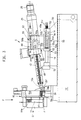
- Fig. 1 Einen Ausschnitt aus der Kunststoff-Spritzgießmaschine in Seitenansicht bei zentraler Spritzachse (Formträger vertikal geschnitten).
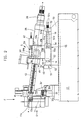
- Fig. 2 den Ausschnitt gemäß Fig. 1 bei verschwenkter Sprtzgießeinheit,
- Fig. 3 den Ausschnitt gemäß den Fign. 1,2 bei zum Leerspritzen des Plastifizierzylinders verschwenkter Spritzgießeinheit,
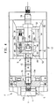
- Fig. 4 den Ausschnitt gemäß Fig. 1 in Draufsicht (horizontal geschnittener Formträger),
- Fig. 5,6 den Ausschnitt gemäß Fig. 1 in Schnitten nach Linien V-V und VI-VI je in vergrößerter Darstellung.
- Es zeigen in einem zweiten Ausführungsbeispiel für eine horizontale Verschwenkung der Spritzgießeinheit:
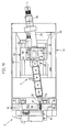
- Fig. 7 Einen Ausschnitt aus der Kunststoff-Spritzgießmaschine in Seitenansicht bei zentraler Spritzachse (Formträger vertikal geschnitten),
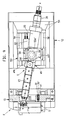
- Fig. 8 den Ausschnitt gemäß Fig. 7 in Draufsicht (Formträger horizontal geschnitten),
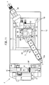
- Fig. 9,10 den Ausschnitt gemäß Fig. 8 bei unterschiedlichen Schwenkstellungen der Spritzgießeinheit,
- Fig. 11 den Ausschnitt gemäß Fig. 7 bei einer in 'Ausbaustellung' befindlichen Spritzgießeinheit,
- Fig. 12,13 den Ausschnitt gemäß Fig. 7 in Schnitten nach Linien XII-XII und XIII-XIII in vergrößerter Darstellung.
- Die Formschließeinheit F ist bei horizontaler Schließrichtung auf dem Maschinenfuß 12 angeordnet. Der stationäre Formträger 15 weist eine Durchtrittsöffnung 15d für die Düse 13a des Plastifizierzylinders 13 auf. In der Formschließeinheit F sind wahlweise eine Spritzgießform (erste Spritzgießform G) mit zentraler Angußöffnung 11 und zentralem Formhohlraum oder weitere Spritzgießformen G′ mit nicht-zentraler Angußöffnung 11a und zentralem Formhohlraum für einen asymmetrischen Anguß einspannbar. Die Spritzgießeinheit S ist auf einer Plattform 55 bzw. 55′ angeordnet, die über eine Konsole 50 parallel zu einer zentralen Spritzachse s-s auf dem Maschinenfuß 12 abgestützt ist. Der Trägerblock 49 nimmt den Plastifizierzylinder 13 stirnseitig in einer Bohrung im Gleitsitz 70 auf. Rückseitig am Trägerblock 49 sind die Antriebsaggregate 25,28 für die Förderschnecke 56 angeordnet. Der Plastifizierzylinder 13 ist mittels radial geführter Schieber 69 in seinem Gleitsitz 70 verriegelbar, die in Verriegelungsposition in Ausnehmungen des Plastifizierzylinders 13 eingreifen. Der Trägerblock 49 ist mit der ihn tragenden Plattform 55;55′ von dem entriegelten und axial arretierten Plastifizierzylinder zwecks dessen Freisetzung nach rückwärts abziehbar. Der Trägerblock 49 ist außerdem über ein rückseitiges Schwenkteil 49b zwischen parallelen Wangen 55a;55b (im Ausführungsbeispiel der Fign. 1 bis 6)bzw. 55a′;55b′ (im Ausführungsbeispiel der Fign. 7 bis 13) der Plattform 55;55′ mittels Drehbolzen 57,57′;58,58′ schwenkbar gelagert. Dadurch ist die Spritzgießeinheit S bedarfsweise aus einer ersten, durch eine zentrale Spritzachse s-s bestimmten Arbeitsstellung für die erste Spritzgießform in einer vorbestimmten Schwenkrichtung (Einspritz-Schwenkrichtung) in wenigstens eine weitere Arbeitseinstellung (Einspritzstellung)(mit Spritzachse w-w) für die weitere Spritzgießform G′ verschwenkbar. Die Verschwenkung erfolgt im Beispiel der Figuren 1 bis 6 in einer durch die zentrale Spritzachse s-s gehenden vertikalen Schwenkebene a-a (Fig. 5,6) und im Beispiel der Figuren 7 bis 13 in einer horizontalen Schwenkebene h-h (Fig. 12,13). Darüberhinaus ist der Trägerblock 49 und damit die Spritzgießeinheit S in einer der Einspritz-Schwenkrichtung entgegengesetzten Schwenkrichtung (Leerspritz-Schwenkrichtung) in der Schwenkebene a-a bzw. h-h in eine Stellung(mit Spritzachse z-z) (Leerspritzstellung) verschwenkbar, in welcher aus der Düse 13a des Plastifizierzylinders 13 unter Druck austretender Kunststoff außerhalb der in Einspritz-Schwenkrichtung erweiterten Durchtrittsöffnung 15d auf eine Stelle (Prallstelle 30) des Formträgers 15 auftrifft. Von dieser kann der erstarrte Kunststoff zur Entsorgung abfallen. Um die Erstarrung zu beschleunigen ist die Prallstelle 30′ mittels eines innerhalb des Formträgers 15 angeordneten Kühlkanal 41 kühlbar, der von einem Kühlmedium durchflossen ist. Der Kühlkanal 41 ist am Umfang eines Schraubenbolzens 30 gebildet, der in einer Bohrung entsprechender lichter Weite in den Formträger 15 eingefügt ist. Somit verläuft der Kühlkanal schraubenförmig und ist einerseits von der Oberfläche des Schraubenbolzens 30 und andererseits von der zylindrischen Innenwand der Bohrung begrenzt. Eine Prallfläche der Prallstelle 30′ ragt aus der rückseitigen Oberfläche des Formträgers 15 hervor. Mit 30a und 30b sind die Zu- und Ableitung für das Kühlmedium bezeichnet.
Das Schwenkteil 49b des Trägerblockes 49 ist zur Verschwenkung an planen Gleitflächen der plattenförmigen Wangen 55a,55b bzw. 55a′,55b′ der Plattform 55;55′ geführt. Als Schwenkeinrichtung findet ein Schneckengetriebe 59 Verwendung, dessen Schneckenrad 59a auf einem Drehbolzen 57 bzw. 57′ sitzt. Die Plattform 55;55′ und ihre Wangen 55a,55b bzw. 55a′, 55b′ sind durch ein einziges Gußstück gebildet. - Die auf einem stationären Säulenpaar 14 geführte Plattform ist mittels eines hydraulischen Antriebszylinders antreibbar. Dieser ist durch eine Zylinderbohrung in der Plattform und durch einen axial festgelegten Kolben 51a gebildet. Das Säulenpaar ist mittels Befestigungsleisten 52 auf der Konsole 50 des Maschinenfußes abgestützt. Die aus Blech geformte Konsole liegt über horizontale Längsränder 50a auf horizontal eingebördelten Rändern 12b des Maschinenfußes 12 auf (Fig. 6,13). Die durchgehende Zylinderbohrung ist beidends mittels Deckel 53,54 abgedeckt, welche die Zylinderräume des hydraulischen Antriebszylinders begrenzen. Der Kolben 51a ist über seine Kolbenstange 51b an der einen Befestigungsleiste 52 axial festgelegt. Die Zylinderräume werden über die Anschlüsse 51c sowie über Axialbohrungen 51d in der Kolbenstange 51b mit dem hydraulischen Medium versorgt.
- Als Schwenkeinrichtung findet ein Schneckengetriebe 59 Verwendung, dessen Schneckenrad 59a auf einem der Drehbolzen (57′ bzw. 58′) sitzt. Die Schwenkbewegung wird mittels eines Potentiometers 66 abgetastet. Wird die Spritzgießeinheit in Leerspritzschwenkrichtung maximal verschwenkt, so ergibt sich eine 'Ausbaustellung' (Fig. 11) für den Ausbau der Förderschnecke bzw. zur Durchführung von Wartungs- und Reparaturarbeiten.
- Das Ausführungsbeispiel gemäß den Figuren 1 bis 6 für vertikale Verschwenkung unterscheidet sich nur wenig von dem Ausführungsbeispiel für horizontale Verschwenkung gemäß den Figuren 7 bis 13: Im Falle einer horizontalen Verschwenkung in der Schwenkebene h-h ist der Potentiometer auf der Seite des Schneckenrades 59a am Schwenkteil 49b angeordnet. Im Falle einer vertikalen Verschwenkung in der Schwenkebene a-a ist der Potentiometer 66 auf der dem Schneckenrad 59a gegenüberliegenden Seite am Schwenkteil 49b angeordnet. Im Beispiel der Fign. 1 bis 6 sind die plattenförmigen vertikalen Wangen 55a,55b im gleichen Abstand von der vertikalen Schwenkebene a-a angeordnet. Das Schneckenrad 59a und die parallel zur Spritzachse angeordnete und in der Wange 55a axial festgelegte Schneckenwelle 59b sind durch einen vertikalen Deckel abgedeckt. Im Beispiel der Fign. 7 bis 13 sind das obere Schneckenrad 59a und die Schneckenwelle 59b mit Hilfe des horizontalen Deckels 63′ abgedeckt. Der obere Drehbolzen 58′ wird von einem Verlängerungszapfen 58a′ durchsetzt, auf dem der Potentiometer 66′ sitzt. Dabei sind die Drehbolzen in horizontalen Wangen 55a′, 55b′ gelagert, die miteinander über einen vertikalen, seitlichen Steg 55d miteinander verbunden sind. Die untere Wange 55b′ ist gewissermaßen durch eine Verdickung der Plattform 55′ gebildet.
- Wie insbesondere aus den Fign. 4 und 7 erkennbar, sind die Schieber 69 zur Verriegelung des Plastifizierzylinders im Schwenkteil in einer Richtung verschiebbar gelagert, die senkrecht zu den Drehbolzen steht.
- Die vorgesehene programmgesteuerte Verriegelung des Plastifizierzylinders mit Hilfe der Schieber 69 ist als solche bekannt. Ebenso das Abziehen einer aus Trägerblock und den Antriebsaggregaten bestehenden Einheit vom Plastifizierzylinder im Gefolge einer Rückwärtsbewegung zur Freisetzung des mittels eines nach Programm radial steuerbaren Arretierbolzens 68 axial arretierbaren Plastifizierzylinders (DE-OS 35 13 411). Das Antriebsaggregat 25 für den Axialhub der Förderschnecke 56 und das Antriebsaggregat 28 für deren Rotation sind freitragend am Trägerblock 49 angeordnet.
- Bei Programmsteuerung liefert der
Potentiometer 66,66′,der als Winkelwegmesser arbeitet, dem Rechner der Kunststoff-Spritzgießmaschine die Signale, die zur Realisierung der jeweils gewünschten Schwenkstellung der Spritzgießeinheit S erforderlich sind. Die programmierbare Schwenkbewegung der Spritzgießeinheit genügt für alle Arbeitseinstellungen einschließlich der Leerspritzstellung und der Ausbaustellung. Auch der Durchfluß des Kühlmediums durch den Kühlkanal 41 im Formträger 15 kann in Abhängigkeit vom Überführen der Spritzgießeinheit in 'Leerspritzstellung' nach Programm des Rechners gesteuert werden. Bei beiden Ausführungsbeispielen bildet der Deckel 63 bzw. 63′ für das Schneckenrad 59a und die Schneckenwelle 59 mit der benachbarten Wange 55a bzw. 55a′ gewissermaßen ein Gehäuse für das Schneckengetriebe 59. In jedem Fall ist die Schneckenwelle 59b von einem Motor 62 angetrieben, der drehfest in der benachbarten Wange 55a bzw. 55a′ abgestützt ist. Die mittels einer Kupplung mit dem Motor 62 kuppelbare Schneckenwelle 59b ist in Lagerelementen 60 der genannten Wange drehbar gelagert. - Der im Beispiel gemäß Fig. 1 bis 6 an der Wange 55b befestigte Potentiometer 66 tastet den benachbarten Drehbolzen 57, der im Beispiel der Fign. 7 bis 13 am Deckel 63′ befestigte Potentiometer 66′ tastet den den Deckel 63′ durchsetzenden Verlängerungszapfen 58a′ des benachbarten Drehbolzens 58′ ab.
- Wie aus Fig. 12 erkennbar, ist der Zentralbereich des Formträgers 15 auf der rechten Seite durch einen Abschnitt 15f verbreitert und im Hinblick auf die erweiterte Durchtrittsöffnung 15d dadurch verstärkt.
Claims (10)
und mit einer, auf einer Plattform (55;55′) des Maschinenfußes (12) angeordneten, mittels einer Antriebseinrichtung (51) axial verschiebbaren Spritzgießeinheit (S) mit einem Trägerblock (49), welcher den Plastifizierzylinder (13) und die Antriebsaggregate (25;28) für die Förderschnecke (56) aufnimmt, sowie mit einer Einrichtung zur bedarfsweisen Verschwenkung der Spritzgießeinheit (S) aus einer ersten, durch eine zentrale Spritzachse (s-s) bestimmten Arbeitseinstellung für die erste Spritzgießform (G) in einer vorbestimmten Schwenkrichtung (Einspritz-Schwenkrichtung) in wenigstens eine weitere Arbeitseinstellung (Einspritzstellung) für die weitere Spritzgießform (G′) in einer durch die zentrale Spritzachse (s-s) gehenden Schwenkebene (a-a in Fig. 5,6; h-h in Fig. 12, 13),
dadurch gekennzeichnet, daß der den Plastifizierzylinder (13) in einem Gleitsitz (70) verriegelbar aufnehmende Trägerblock (49) mit der ihn tragenden Plattform (55;55′) von dem entriegelten und axial arretierten Plastifizierzylinder zwecks dessen Freisetzung nach rückwärts abziehbar, über ein rückseitiges Schwenkteil (49b) zwischen parallelen Wangen (55a,55b bzw. 55a′,55b′) der Plattform (55;55′) mittels Drehbolzen (57,57′;58,58′) schwenkbar gelagert und in einer der Einspritzschwenkrichtung entgegengesetzten Schwenkrichtung (Leerspritzschwenkrichtung) in der Schwenkebene (a-a;h-h) in eine Stellung (Leerspritzstellung) verschwenkbar ist, in welcher aus der Düse (13a) des Plastifizierzylinders (13) unter Druck austretender Kunststoff außerhalb der in Einspritzschwenkrichtung erweiterten Durchtrittsöffnung (15d) auf eine Stelle (Prallstelle 30′) des Formträgers (15) auftrifft, von welcher der beim Auftreffen erstarrte Kunststoff zur Entsorgung abfallen kann.
Priority Applications (1)
| Application Number | Priority Date | Filing Date | Title |
|---|---|---|---|
| AT88108750T ATE72540T1 (de) | 1987-07-30 | 1988-06-01 | Kunststoff-spritzgiessmaschine fuer wahlweise zentrale oder lineare formfuellung. |
Applications Claiming Priority (2)
| Application Number | Priority Date | Filing Date | Title |
|---|---|---|---|
| DE19873725220 DE3725220A1 (de) | 1987-07-30 | 1987-07-30 | Kunststoff-spritzgiessmaschine mit einer in unterschiedliche arbeitseinstellungen ueberfuehrbaren spritzgiesseinheit |
| DE3725220 | 1987-07-30 |
Publications (3)
| Publication Number | Publication Date |
|---|---|
| EP0301200A2 true EP0301200A2 (de) | 1989-02-01 |
| EP0301200A3 EP0301200A3 (en) | 1989-12-27 |
| EP0301200B1 EP0301200B1 (de) | 1992-02-12 |
Family
ID=6332682
Family Applications (1)
| Application Number | Title | Priority Date | Filing Date |
|---|---|---|---|
| EP88108750A Expired - Lifetime EP0301200B1 (de) | 1987-07-30 | 1988-06-01 | Kunststoff-Spritzgiessmaschine für wahlweise zentrale oder lineare Formfüllung |
Country Status (9)
| Country | Link |
|---|---|
| US (1) | US4863368A (de) |
| EP (1) | EP0301200B1 (de) |
| JP (1) | JPS6449611A (de) |
| AT (1) | ATE72540T1 (de) |
| CA (1) | CA1291307C (de) |
| DE (2) | DE3725220A1 (de) |
| ES (1) | ES2030460T3 (de) |
| HK (1) | HK100592A (de) |
| SG (1) | SG97892G (de) |
Cited By (2)
| Publication number | Priority date | Publication date | Assignee | Title |
|---|---|---|---|---|
| EP0368149A3 (de) * | 1988-11-05 | 1991-05-22 | Karl Hehl | Kunststoff-Spritzgiessmaschine |
| CN109531911A (zh) * | 2019-01-25 | 2019-03-29 | 徐嘉辉 | 一种用于注塑模具的喷嘴结构 |
Families Citing this family (15)
| Publication number | Priority date | Publication date | Assignee | Title |
|---|---|---|---|---|
| DE4018484C2 (de) * | 1990-06-09 | 1996-02-01 | Tetra Pak Gmbh | Vorrichtung zum Anspritzen eines Kunststoffteils an ein Werkstück und Verwendung der Vorrichtung zur Herstellung einer Fließmittelpackung |
| DE4227336C1 (de) * | 1992-08-18 | 1994-03-31 | Karl Hehl | Kunststoff-Spritzgießmaschine |
| US6352427B1 (en) * | 2000-04-06 | 2002-03-05 | Mgs Mfg. Group, Inc. | Multi-shot injection molding arrangement |
| US6994810B2 (en) * | 2000-04-06 | 2006-02-07 | Mgs Mfg. Group, Inc. | Multi-shot injection molding arrangement |
| US7393199B2 (en) * | 2000-04-06 | 2008-07-01 | Mgs Mfg. Group, Inc. | Multi-shot injection molding arrangement |
| US6837856B2 (en) | 2001-09-19 | 2005-01-04 | Matsushita Electric Industrial Co., Ltd. | Ultrasonic search unit and method for producing the same |
| DE10337785B3 (de) * | 2003-08-14 | 2004-11-04 | Demag Ergotech Gmbh | Düsenanpressvorrichtung |
| US20070087080A1 (en) * | 2003-09-09 | 2007-04-19 | Robert Weinmann | Injection unit, and method for the adjustment thereof |
| US7399179B2 (en) * | 2006-08-15 | 2008-07-15 | Husky Injection Molding Systems Ltd. | Injection unit mount |
| PT2906405T (pt) * | 2012-10-15 | 2019-04-18 | Mold Masters 2007 Ltd | Aparelho de posicionamento de unidade de injeção |
| PT3370939T (pt) | 2015-11-06 | 2021-11-11 | Mold Masters 2007 Ltd | Aparelho de posicionamento de unidade de injeção |
| DE102018118376A1 (de) * | 2018-07-30 | 2020-01-30 | Kraussmaffei Technologies Gmbh | Plastifiziereinheit |
| CN109834908B (zh) * | 2019-04-17 | 2023-09-26 | 四川立民制冷科技有限公司 | 多功能聚双环戊二烯材料注射机 |
| JP7319132B2 (ja) * | 2019-07-31 | 2023-08-01 | ファナック株式会社 | 射出成形機 |
| CN116100818B (zh) * | 2022-12-27 | 2024-08-20 | 哈威光电科技(苏州)有限公司 | 一种注塑粒子与料带粘结贴合组装一体机 |
Family Cites Families (12)
| Publication number | Priority date | Publication date | Assignee | Title |
|---|---|---|---|---|
| DE1852612U (de) * | 1962-03-22 | 1962-05-30 | Krauss Maffei Ag | Spritzgussmaschine zum verarbeiten thermoplastischer kunststoffe. |
| US3335464A (en) * | 1965-03-03 | 1967-08-15 | Lester Engineering Co | Injection molding machine |
| US3464091A (en) * | 1965-09-16 | 1969-09-02 | Eckert Und Ziegler Gmbh | Injection molding machine |
| US3577843A (en) * | 1969-04-09 | 1971-05-11 | Louis F Kutik | Apparatus for controlling bristle deflection |
| DE6942324U (de) * | 1969-10-31 | 1970-07-02 | Fahr Bucher Gmbh | Hydraulische presse. |
| US3729280A (en) * | 1969-12-10 | 1973-04-24 | Hehl Karl | Injection molding unit |
| DE2504719A1 (de) * | 1975-02-05 | 1976-08-19 | Fahr Bucher Gmbh | Spritzgiessmaschine |
| JPS61185423A (ja) * | 1985-02-13 | 1986-08-19 | Dainichi Nippon Cables Ltd | 射出成形機 |
| DE3683181D1 (de) * | 1985-04-15 | 1992-02-13 | Karl Hehl | Spritzgiessmaschine fuer kunststoffe. |
| EP0198364B1 (de) * | 1985-04-15 | 1991-01-02 | Karl Hehl | Kunststoff-Spritzgiesseinheit |
| DE3513411A1 (de) * | 1985-04-15 | 1986-10-16 | Karl 7298 Loßburg Hehl | Kunststoff-spritzgiessmaschine |
| JPH0325948Y2 (de) * | 1985-09-09 | 1991-06-05 |
-
1987
- 1987-07-30 DE DE19873725220 patent/DE3725220A1/de not_active Withdrawn
-
1988
- 1988-06-01 DE DE8888108750T patent/DE3868365D1/de not_active Expired - Lifetime
- 1988-06-01 EP EP88108750A patent/EP0301200B1/de not_active Expired - Lifetime
- 1988-06-01 AT AT88108750T patent/ATE72540T1/de not_active IP Right Cessation
- 1988-06-01 ES ES198888108750T patent/ES2030460T3/es not_active Expired - Lifetime
- 1988-07-25 CA CA000572901A patent/CA1291307C/en not_active Expired - Lifetime
- 1988-07-25 JP JP63183739A patent/JPS6449611A/ja active Granted
- 1988-07-29 US US07/226,537 patent/US4863368A/en not_active Expired - Fee Related
-
1992
- 1992-09-29 SG SG978/92A patent/SG97892G/en unknown
- 1992-12-10 HK HK1005/92A patent/HK100592A/xx unknown
Cited By (2)
| Publication number | Priority date | Publication date | Assignee | Title |
|---|---|---|---|---|
| EP0368149A3 (de) * | 1988-11-05 | 1991-05-22 | Karl Hehl | Kunststoff-Spritzgiessmaschine |
| CN109531911A (zh) * | 2019-01-25 | 2019-03-29 | 徐嘉辉 | 一种用于注塑模具的喷嘴结构 |
Also Published As
| Publication number | Publication date |
|---|---|
| DE3868365D1 (de) | 1992-03-26 |
| ES2030460T3 (es) | 1992-11-01 |
| ATE72540T1 (de) | 1992-02-15 |
| DE3725220A1 (de) | 1989-02-16 |
| EP0301200A3 (en) | 1989-12-27 |
| EP0301200B1 (de) | 1992-02-12 |
| SG97892G (en) | 1993-01-29 |
| US4863368A (en) | 1989-09-05 |
| CA1291307C (en) | 1991-10-29 |
| JPH0515530B2 (de) | 1993-03-01 |
| HK100592A (en) | 1992-12-18 |
| JPS6449611A (en) | 1989-02-27 |
Similar Documents
| Publication | Publication Date | Title |
|---|---|---|
| EP0301200B1 (de) | Kunststoff-Spritzgiessmaschine für wahlweise zentrale oder lineare Formfüllung | |
| DE10164900B4 (de) | Formschließvorrichtung für eine Spritzgießmaschine | |
| CH663569A5 (de) | Beschickungseinrichtung zum zufuehren von kunststoffgranulat in eine spritzgiesseinheit. | |
| EP0291008B1 (de) | Kunststoff-Spritzgiessmaschine mit einer in unterschiedliche Arbeitsstellungen überführbaren Spritzgiesseinheit | |
| DE4314941C2 (de) | Spritzeinheit an Spritzgießmaschinen zur Herstellung thermoplastischer Kunststoffteile | |
| DE29623468U1 (de) | Form zur Herstellung von Formsteinen | |
| DE2112311B2 (de) | Kunststoff-Spritzgießmaschine mit einer eine Spritzgießform aufnehmenden Formschließeinheit | |
| DE69109757T3 (de) | Steuereinheit für Unterdrucksetzung. | |
| WO2000069611A2 (de) | Vorrichtung zum herstellen von kunststoff-formteilen | |
| EP0285982A2 (de) | Verfahren und Vorrichtung zum Herstellen eines Formteils aus einer faserhaltigen, duroplastischen Formmasse | |
| DE2544749B2 (de) | Mit einem mischkopf kombiniertes formwerkzeug zum herstellen von formteilen | |
| CH404187A (de) | Maschine zum Spritzen von Formstücken aus Kunststoff | |
| EP0200962B1 (de) | Spritzgiesseinheit für eine Kunststoff-Spritzgiessmaschine | |
| DE2112535A1 (de) | Angussvorrichtung fuer die formgebende Verarbeitung von aus mehreren fluessigen Komponenten sich bildenden Kunststoffen,insbesondere von zellbildenden Kunststoffen | |
| DE3705470A1 (de) | Verfahren zum herstellen von formteilen aus kunststoff und vorrichtung zur durchfuehrung desselben | |
| DE3513411C2 (de) | ||
| DE3327135A1 (de) | Vorrichtung zum giessen von pur-schaumgemischen in offene hohlformen | |
| DE3117014C2 (de) | Vorrichtung zum Erzeugen eines insbesondere schäumfähigen Gemisches aus mindestens zwei vorzugsweise chemisch reaktionsfähigen Kunststoffkomponenten | |
| DE3605219C2 (de) | ||
| AT396445B (de) | Spritzgiessmaschine | |
| WO2001043858A2 (de) | Vorrichtung zum mischen von viskosen flüssigkeiten | |
| DE19521130C2 (de) | Vorrichtung zum Mischen eines körnigen Gutes mit einer Flüssigkeit | |
| DE19819055C1 (de) | Schwenkvorrichtung für die Spritzgießeinheit einer Spritzgießmaschine | |
| DE2916133A1 (de) | Kunststoffspritzgussmaschine | |
| DE19721375C2 (de) | Formträger für die Kunststoffverarbeitung insbesondere das Reaktionsschäumverfahren |
Legal Events
| Date | Code | Title | Description |
|---|---|---|---|
| PUAI | Public reference made under article 153(3) epc to a published international application that has entered the european phase |
Free format text: ORIGINAL CODE: 0009012 |
|
| AK | Designated contracting states |
Kind code of ref document: A2 Designated state(s): AT CH DE ES FR GB IT LI NL |
|
| PUAL | Search report despatched |
Free format text: ORIGINAL CODE: 0009013 |
|
| AK | Designated contracting states |
Kind code of ref document: A3 Designated state(s): AT CH DE ES FR GB IT LI NL |
|
| 17P | Request for examination filed |
Effective date: 19900615 |
|
| 17Q | First examination report despatched |
Effective date: 19910712 |
|
| GRAA | (expected) grant |
Free format text: ORIGINAL CODE: 0009210 |
|
| AK | Designated contracting states |
Kind code of ref document: B1 Designated state(s): AT CH DE ES FR GB IT LI NL |
|
| REF | Corresponds to: |
Ref document number: 72540 Country of ref document: AT Date of ref document: 19920215 Kind code of ref document: T |
|
| REF | Corresponds to: |
Ref document number: 3868365 Country of ref document: DE Date of ref document: 19920326 |
|
| ITF | It: translation for a ep patent filed | ||
| ET | Fr: translation filed | ||
| GBT | Gb: translation of ep patent filed (gb section 77(6)(a)/1977) | ||
| REG | Reference to a national code |
Ref country code: ES Ref legal event code: FG2A Ref document number: 2030460 Country of ref document: ES Kind code of ref document: T3 |
|
| PLBE | No opposition filed within time limit |
Free format text: ORIGINAL CODE: 0009261 |
|
| STAA | Information on the status of an ep patent application or granted ep patent |
Free format text: STATUS: NO OPPOSITION FILED WITHIN TIME LIMIT |
|
| 26N | No opposition filed | ||
| PGFP | Annual fee paid to national office [announced via postgrant information from national office to epo] |
Ref country code: GB Payment date: 19930524 Year of fee payment: 6 |
|
| PGFP | Annual fee paid to national office [announced via postgrant information from national office to epo] |
Ref country code: FR Payment date: 19930616 Year of fee payment: 6 |
|
| PGFP | Annual fee paid to national office [announced via postgrant information from national office to epo] |
Ref country code: ES Payment date: 19930629 Year of fee payment: 6 |
|
| PGFP | Annual fee paid to national office [announced via postgrant information from national office to epo] |
Ref country code: NL Payment date: 19930630 Year of fee payment: 6 |
|
| PGFP | Annual fee paid to national office [announced via postgrant information from national office to epo] |
Ref country code: CH Payment date: 19930719 Year of fee payment: 6 |
|
| PG25 | Lapsed in a contracting state [announced via postgrant information from national office to epo] |
Ref country code: GB Effective date: 19940601 |
|
| PG25 | Lapsed in a contracting state [announced via postgrant information from national office to epo] |
Ref country code: ES Free format text: LAPSE BECAUSE OF EXPIRATION OF PROTECTION Effective date: 19940602 |
|
| PG25 | Lapsed in a contracting state [announced via postgrant information from national office to epo] |
Ref country code: LI Effective date: 19940630 Ref country code: CH Effective date: 19940630 |
|
| PG25 | Lapsed in a contracting state [announced via postgrant information from national office to epo] |
Ref country code: NL Effective date: 19950101 |
|
| GBPC | Gb: european patent ceased through non-payment of renewal fee |
Effective date: 19940601 |
|
| NLV4 | Nl: lapsed or anulled due to non-payment of the annual fee | ||
| PG25 | Lapsed in a contracting state [announced via postgrant information from national office to epo] |
Ref country code: FR Effective date: 19950228 |
|
| REG | Reference to a national code |
Ref country code: CH Ref legal event code: PL |
|
| REG | Reference to a national code |
Ref country code: FR Ref legal event code: ST |
|
| PGFP | Annual fee paid to national office [announced via postgrant information from national office to epo] |
Ref country code: DE Payment date: 19950508 Year of fee payment: 8 |
|
| PGFP | Annual fee paid to national office [announced via postgrant information from national office to epo] |
Ref country code: AT Payment date: 19950623 Year of fee payment: 8 |
|
| PG25 | Lapsed in a contracting state [announced via postgrant information from national office to epo] |
Ref country code: AT Effective date: 19960601 |
|
| PG25 | Lapsed in a contracting state [announced via postgrant information from national office to epo] |
Ref country code: DE Effective date: 19970301 |
|
| REG | Reference to a national code |
Ref country code: ES Ref legal event code: FD2A Effective date: 20000601 |
|
| PG25 | Lapsed in a contracting state [announced via postgrant information from national office to epo] |
Ref country code: IT Free format text: LAPSE BECAUSE OF NON-PAYMENT OF DUE FEES;WARNING: LAPSES OF ITALIAN PATENTS WITH EFFECTIVE DATE BEFORE 2007 MAY HAVE OCCURRED AT ANY TIME BEFORE 2007. THE CORRECT EFFECTIVE DATE MAY BE DIFFERENT FROM THE ONE RECORDED. Effective date: 20050601 |