EP0301209A2 - Dispositif de commande pour fauteuils roulants électriques et appareils semblables - Google Patents
Dispositif de commande pour fauteuils roulants électriques et appareils semblables Download PDFInfo
- Publication number
- EP0301209A2 EP0301209A2 EP88109238A EP88109238A EP0301209A2 EP 0301209 A2 EP0301209 A2 EP 0301209A2 EP 88109238 A EP88109238 A EP 88109238A EP 88109238 A EP88109238 A EP 88109238A EP 0301209 A2 EP0301209 A2 EP 0301209A2
- Authority
- EP
- European Patent Office
- Prior art keywords
- control device
- mechanical
- plates
- control lever
- lever
- Prior art date
- Legal status (The legal status is an assumption and is not a legal conclusion. Google has not performed a legal analysis and makes no representation as to the accuracy of the status listed.)
- Granted
Links
Images

Classifications
-
- G—PHYSICS
- G05—CONTROLLING; REGULATING
- G05G—CONTROL DEVICES OR SYSTEMS INSOFAR AS CHARACTERISED BY MECHANICAL FEATURES ONLY
- G05G9/00—Manually-actuated control mechanisms provided with one single controlling member co-operating with two or more controlled members, e.g. selectively, simultaneously
- G05G9/02—Manually-actuated control mechanisms provided with one single controlling member co-operating with two or more controlled members, e.g. selectively, simultaneously the controlling member being movable in different independent ways, movement in each individual way actuating one controlled member only
- G05G9/04—Manually-actuated control mechanisms provided with one single controlling member co-operating with two or more controlled members, e.g. selectively, simultaneously the controlling member being movable in different independent ways, movement in each individual way actuating one controlled member only in which movement in two or more ways can occur simultaneously
- G05G9/047—Manually-actuated control mechanisms provided with one single controlling member co-operating with two or more controlled members, e.g. selectively, simultaneously the controlling member being movable in different independent ways, movement in each individual way actuating one controlled member only in which movement in two or more ways can occur simultaneously the controlling member being movable by hand about orthogonal axes, e.g. joysticks
-
- G—PHYSICS
- G05—CONTROLLING; REGULATING
- G05G—CONTROL DEVICES OR SYSTEMS INSOFAR AS CHARACTERISED BY MECHANICAL FEATURES ONLY
- G05G9/00—Manually-actuated control mechanisms provided with one single controlling member co-operating with two or more controlled members, e.g. selectively, simultaneously
- G05G9/02—Manually-actuated control mechanisms provided with one single controlling member co-operating with two or more controlled members, e.g. selectively, simultaneously the controlling member being movable in different independent ways, movement in each individual way actuating one controlled member only
- G05G9/04—Manually-actuated control mechanisms provided with one single controlling member co-operating with two or more controlled members, e.g. selectively, simultaneously the controlling member being movable in different independent ways, movement in each individual way actuating one controlled member only in which movement in two or more ways can occur simultaneously
- G05G9/047—Manually-actuated control mechanisms provided with one single controlling member co-operating with two or more controlled members, e.g. selectively, simultaneously the controlling member being movable in different independent ways, movement in each individual way actuating one controlled member only in which movement in two or more ways can occur simultaneously the controlling member being movable by hand about orthogonal axes, e.g. joysticks
- G05G9/04785—Manually-actuated control mechanisms provided with one single controlling member co-operating with two or more controlled members, e.g. selectively, simultaneously the controlling member being movable in different independent ways, movement in each individual way actuating one controlled member only in which movement in two or more ways can occur simultaneously the controlling member being movable by hand about orthogonal axes, e.g. joysticks the controlling member being the operating part of a switch arrangement
-
- G—PHYSICS
- G05—CONTROLLING; REGULATING
- G05G—CONTROL DEVICES OR SYSTEMS INSOFAR AS CHARACTERISED BY MECHANICAL FEATURES ONLY
- G05G9/00—Manually-actuated control mechanisms provided with one single controlling member co-operating with two or more controlled members, e.g. selectively, simultaneously
- G05G9/02—Manually-actuated control mechanisms provided with one single controlling member co-operating with two or more controlled members, e.g. selectively, simultaneously the controlling member being movable in different independent ways, movement in each individual way actuating one controlled member only
- G05G9/04—Manually-actuated control mechanisms provided with one single controlling member co-operating with two or more controlled members, e.g. selectively, simultaneously the controlling member being movable in different independent ways, movement in each individual way actuating one controlled member only in which movement in two or more ways can occur simultaneously
- G05G9/047—Manually-actuated control mechanisms provided with one single controlling member co-operating with two or more controlled members, e.g. selectively, simultaneously the controlling member being movable in different independent ways, movement in each individual way actuating one controlled member only in which movement in two or more ways can occur simultaneously the controlling member being movable by hand about orthogonal axes, e.g. joysticks
- G05G2009/04703—Mounting of controlling member
- G05G2009/04707—Mounting of controlling member with ball joint
-
- G—PHYSICS
- G05—CONTROLLING; REGULATING
- G05G—CONTROL DEVICES OR SYSTEMS INSOFAR AS CHARACTERISED BY MECHANICAL FEATURES ONLY
- G05G9/00—Manually-actuated control mechanisms provided with one single controlling member co-operating with two or more controlled members, e.g. selectively, simultaneously
- G05G9/02—Manually-actuated control mechanisms provided with one single controlling member co-operating with two or more controlled members, e.g. selectively, simultaneously the controlling member being movable in different independent ways, movement in each individual way actuating one controlled member only
- G05G9/04—Manually-actuated control mechanisms provided with one single controlling member co-operating with two or more controlled members, e.g. selectively, simultaneously the controlling member being movable in different independent ways, movement in each individual way actuating one controlled member only in which movement in two or more ways can occur simultaneously
- G05G9/047—Manually-actuated control mechanisms provided with one single controlling member co-operating with two or more controlled members, e.g. selectively, simultaneously the controlling member being movable in different independent ways, movement in each individual way actuating one controlled member only in which movement in two or more ways can occur simultaneously the controlling member being movable by hand about orthogonal axes, e.g. joysticks
- G05G2009/0474—Manually-actuated control mechanisms provided with one single controlling member co-operating with two or more controlled members, e.g. selectively, simultaneously the controlling member being movable in different independent ways, movement in each individual way actuating one controlled member only in which movement in two or more ways can occur simultaneously the controlling member being movable by hand about orthogonal axes, e.g. joysticks characterised by means converting mechanical movement into electric signals
- G05G2009/04744—Switches
-
- G—PHYSICS
- G05—CONTROLLING; REGULATING
- G05G—CONTROL DEVICES OR SYSTEMS INSOFAR AS CHARACTERISED BY MECHANICAL FEATURES ONLY
- G05G9/00—Manually-actuated control mechanisms provided with one single controlling member co-operating with two or more controlled members, e.g. selectively, simultaneously
- G05G9/02—Manually-actuated control mechanisms provided with one single controlling member co-operating with two or more controlled members, e.g. selectively, simultaneously the controlling member being movable in different independent ways, movement in each individual way actuating one controlled member only
- G05G9/04—Manually-actuated control mechanisms provided with one single controlling member co-operating with two or more controlled members, e.g. selectively, simultaneously the controlling member being movable in different independent ways, movement in each individual way actuating one controlled member only in which movement in two or more ways can occur simultaneously
- G05G9/047—Manually-actuated control mechanisms provided with one single controlling member co-operating with two or more controlled members, e.g. selectively, simultaneously the controlling member being movable in different independent ways, movement in each individual way actuating one controlled member only in which movement in two or more ways can occur simultaneously the controlling member being movable by hand about orthogonal axes, e.g. joysticks
- G05G2009/0474—Manually-actuated control mechanisms provided with one single controlling member co-operating with two or more controlled members, e.g. selectively, simultaneously the controlling member being movable in different independent ways, movement in each individual way actuating one controlled member only in which movement in two or more ways can occur simultaneously the controlling member being movable by hand about orthogonal axes, e.g. joysticks characterised by means converting mechanical movement into electric signals
- G05G2009/04748—Position sensor for rotary movement, e.g. potentiometer
-
- G—PHYSICS
- G05—CONTROLLING; REGULATING
- G05G—CONTROL DEVICES OR SYSTEMS INSOFAR AS CHARACTERISED BY MECHANICAL FEATURES ONLY
- G05G9/00—Manually-actuated control mechanisms provided with one single controlling member co-operating with two or more controlled members, e.g. selectively, simultaneously
- G05G9/02—Manually-actuated control mechanisms provided with one single controlling member co-operating with two or more controlled members, e.g. selectively, simultaneously the controlling member being movable in different independent ways, movement in each individual way actuating one controlled member only
- G05G9/04—Manually-actuated control mechanisms provided with one single controlling member co-operating with two or more controlled members, e.g. selectively, simultaneously the controlling member being movable in different independent ways, movement in each individual way actuating one controlled member only in which movement in two or more ways can occur simultaneously
- G05G9/047—Manually-actuated control mechanisms provided with one single controlling member co-operating with two or more controlled members, e.g. selectively, simultaneously the controlling member being movable in different independent ways, movement in each individual way actuating one controlled member only in which movement in two or more ways can occur simultaneously the controlling member being movable by hand about orthogonal axes, e.g. joysticks
- G05G2009/0474—Manually-actuated control mechanisms provided with one single controlling member co-operating with two or more controlled members, e.g. selectively, simultaneously the controlling member being movable in different independent ways, movement in each individual way actuating one controlled member only in which movement in two or more ways can occur simultaneously the controlling member being movable by hand about orthogonal axes, e.g. joysticks characterised by means converting mechanical movement into electric signals
- G05G2009/04751—Position sensor for linear movement
-
- G—PHYSICS
- G05—CONTROLLING; REGULATING
- G05G—CONTROL DEVICES OR SYSTEMS INSOFAR AS CHARACTERISED BY MECHANICAL FEATURES ONLY
- G05G9/00—Manually-actuated control mechanisms provided with one single controlling member co-operating with two or more controlled members, e.g. selectively, simultaneously
- G05G9/02—Manually-actuated control mechanisms provided with one single controlling member co-operating with two or more controlled members, e.g. selectively, simultaneously the controlling member being movable in different independent ways, movement in each individual way actuating one controlled member only
- G05G9/04—Manually-actuated control mechanisms provided with one single controlling member co-operating with two or more controlled members, e.g. selectively, simultaneously the controlling member being movable in different independent ways, movement in each individual way actuating one controlled member only in which movement in two or more ways can occur simultaneously
- G05G9/047—Manually-actuated control mechanisms provided with one single controlling member co-operating with two or more controlled members, e.g. selectively, simultaneously the controlling member being movable in different independent ways, movement in each individual way actuating one controlled member only in which movement in two or more ways can occur simultaneously the controlling member being movable by hand about orthogonal axes, e.g. joysticks
- G05G2009/04766—Manually-actuated control mechanisms provided with one single controlling member co-operating with two or more controlled members, e.g. selectively, simultaneously the controlling member being movable in different independent ways, movement in each individual way actuating one controlled member only in which movement in two or more ways can occur simultaneously the controlling member being movable by hand about orthogonal axes, e.g. joysticks providing feel, e.g. indexing means, means to create counterforce
-
- H—ELECTRICITY
- H01—ELECTRIC ELEMENTS
- H01H—ELECTRIC SWITCHES; RELAYS; SELECTORS; EMERGENCY PROTECTIVE DEVICES
- H01H3/00—Mechanisms for operating contacts
- H01H3/02—Operating parts, i.e. for operating driving mechanism by a mechanical force external to the switch
- H01H3/0213—Combined operation of electric switch and variable impedance, e.g. resistor, capacitor
Definitions
- the invention relates to a control device of the type mentioned in the preamble of claim 1 for electric wheelchairs or the like.
- a control device is often called a joystick.
- a control device of the type in question, in which the mechanical-electrical actuators consist of potentiometers, is known from the company publication "Wheelchairs and Rehabilitation Aids" from MEYRA in D-4925 Kalletal 1, August 1984, page 79, and the wheelchairs supplied by this company. whose axes are offset by 90 ° in a plane substantially perpendicular to the direction of the control lever.
- the ends of one leg of a U-shaped bracket are fastened to the axes, in the middle part of which there are slots in which one end of the two-armed control lever engages.
- the central parts of the U-shaped bracket, in which the slots are located, are designed in an arc shape in accordance with the path of movement of the control lever with respect to its pivot bearing.
- the manufacture is thus complicated, in particular the manufacture of the part in the form of an arc ordered slot.
- an additional pivot bearing is provided at the end of the leg of the U-shaped bracket, which faces away from the potentiometer. This also represents an additional design effort. Because of the U-shaped bracket, the overall depth is relatively large, which is particularly disadvantageous because a control device of the type in question must be accommodated in or in the armrest of the wheelchair when used in a wheelchair .
- the invention has for its object to provide a control device of the type in question, which does not have the disadvantages of the known control device, which is simple and cheap in construction and has a low overall depth.
- link gears are used as mechanical transmission devices.
- link mechanism there is a small overall depth with a simple outlay.
- the control lever simply engages a link which rests on the control lever and is moved during movements which do not take place along the contour of the link, this movement being transmitted to the mechanical-electrical actuator.
- the backdrop and its guidance can be produced in a very simple manner, so that there are low manufacturing costs.
- the overall depth is also very small.
- the link gears can have two slides which are held displaceably in the same direction and each have slotted slots in the opposite direction to their direction of movement, into which the control lever engages, the sliders being connected to the mechanical-electrical actuators. Because the slides can be moved in the same direction, practically the same guide can be used for them, which is structurally particularly simple.
- the scenes slots can be produced in a very simple manner and very precisely, for example by punching out if the slides are formed by plates.
- the transfer function can be varied within very wide limits, so that there are corresponding possible variations in the control characteristics of the control lever.
- the link slots can be inclined by 45 ° to the direction of displacement, but other angles are also possible, which results in a different control characteristic when the control lever is deflected in different directions.
- a particular advantage in the use of the scenes is that they enable very different control characteristics not only due to the inclination, but also due to the shape of the curve.
- the backdrops or the backdrop slots can therefore be curved.
- a particularly expedient form of training of the slider designed as plates with the slot slots is specified in claim 6.
- the plates are guided very simply by way of superimposed guide slots in the plates, into which a guide pin common to both plates engages, which thus guides both plates simultaneously.
- Axial to the guide pin of course, contact shoulders are required to hold and guide the plates on the pins in their position.
- These contact shoulders and the plates themselves can be made of a suitable material, preferably of plastic, which does not require lubrication, so that a completely maintenance-free and largely wear-free construction is provided.
- a socket extends through the intersecting slots with little least one flange rests on one of the plates, the control lever engaging with an at least partially spherical part in the socket.
- the plates forming the slide can lie tightly, preferably directly on top of one another. This is constructively expedient and is possible because the managers perpendicular to the plates and therefore the support forces of the plates on one another are very low.
- slides for the link gears enables a very expedient further development, since the arrangement of lateral projections or depressions on the slides is possible, which can cooperate with an actuator of a switch.
- a switch is used in the case of a wheelchair to perform certain switching operations when the operator releases the control lever.
- recesses are provided on each of the two slides, which are in alignment with one another in the rest position of the control lever, such that the switch is actuated only in the rest position of the control lever.
- the mechanical-electrical actuators can be flat track resistors or flat track potentiometers in a very simple manner, which are connected directly or indirectly to the slides by small transmission rods. This results in completely linear control characteristics, while the overall depth is particularly small.
- Rotary resistors or rotary potentiometers can also be used as mechanical-electrical actuators, on the axis of which a lever is fastened, each with a lever on the slide arranged pin is engaged. The position of the rotary resistors or rotary potentiometers is completely free except for the condition that their axis must run perpendicular to the direction of displacement of the slide.
- This embodiment therefore enables an arbitrary arrangement of the rotary resistors or rotary potentiometers, in particular one in which the overall depth is very small.
- the lever required for the rotary movement of the rotary resistors or rotary potentiometer is advantageously a fork into which a pin on the slide engages.
- the actuators can also work inductively.
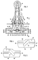
- a control lever 1 has a ball joint 2, the ball part 3 sits on the control lever 1 and the fixed part 4 is held by a housing part 5 on a plate 6, with which the entire control device can be fastened, for example, by screws in the armrest of a wheelchair.
- the housing part 5 is held by means of screws 7, which simultaneously hold a stop ring 8, the stop edge 9 of which limits the deflection movements of the control lever 1.
- a bushing 11 is displaceably arranged, which is pressed by a compression spring 12 with its lower edge 13 against a disk 14 which is held by the stop ring 8 on the upper surface of the plate 6 .
- the compression spring 12 is supported on a screw ring 15, which is adjustable on a thread 16 of the upper arm 10 to the pressure force of the spring 12 and thus the contact of the lower edge 13 on the disc 14 and thus also the restoring force of the resulting To be able to adjust control lever 1.
- the upper arm 10 with the compression spring 12 is covered by a cap 17 which is held by a ball 18 which is screwed onto a threaded end 19 of the upper arm 10.
- a seal 20 extends between the bushing 11 and the stop ring 8.
- the housing part 5 has a round flange 21 in which there are diametrically opposite holes 22 and 23 through which screws 24 and 25 extend, which hold the washers 26 and 27, bushings 28 and 29 and washers 30 and 31, all of which pass through Nuts 32 and 33 are pulled against the flange 21.
- Two plates 34 and 35 are slidably guided between the disks 26, 27 and 30, 31, the bushes 28 and 29 sliding in the plates 34 and 35 in slots 36 and 37 without play.
- the formation of the plates 34 and 35 and the arrangement of the slots 36 and 37 can be clearly seen from FIG. 3.
- the plates 34 and 35 are thus easily displaceable and free of play in the direction of the slots 36 and 37.
- a link slot 40 inclined in the direction of displacement by 45 ° in the plate 35 and a link slot 41 in the plate 36.
- a socket 42 which is dimensioned so that it can slide in the link slots without play.
- a flange 43 is located on the bushing 42 and slidably abuts the plate 34.
- a disc 44 is pushed onto the latter, which lies against the plate 35 and is held on the socket by a locking ring 45.
- a pin 48 which engages without play in the mouth of a fork 49 which is attached as a lever to an axis 50 of a potentiometer 51, so that the lever 49 is pivoted when the plate 35 and thus the pin 48 are displaced and the axis 50 of the potentiometer 51 is rotated.
- FIGS. 4 and 5 there is a depression 58 on an edge 57 of the plate 35, while a depression 60 is located on an edge 59 of the plate 34.
- These depressions 58, 60 cooperate with a control roller 61 on an actuating arm 62 of a microswitch 63.
- the control roller 61 is resting in the superimposed recesses 58, 60, so that the microswitch 63 is closed or opened depending on its design, while it opens or closes when the plates 34 or 35 migrate.
- Opposing edges 64 and 65 have elongated edges Indentations which cooperate with a control roller 66 on an actuating arm 67 of a microswitch 68, the actuation of this microswitch 68 being actuated in the end displacement positions of the plates 34 and 35, respectively.
Landscapes
- Physics & Mathematics (AREA)
- General Physics & Mathematics (AREA)
- Engineering & Computer Science (AREA)
- Automation & Control Theory (AREA)
- Mechanical Control Devices (AREA)
Applications Claiming Priority (3)
| Application Number | Priority Date | Filing Date | Title |
|---|---|---|---|
| DE19873724915 DE3724915A1 (de) | 1987-07-28 | 1987-07-28 | Steuereinrichtung fuer elektrische rollstuehle oder dergl. |
| DE8710311U DE8710311U1 (de) | 1987-07-28 | 1987-07-28 | Steuereinrichtung für elektrische Rollstühle od.dgl. |
| DE3724915 | 1987-07-28 |
Publications (3)
| Publication Number | Publication Date |
|---|---|
| EP0301209A2 true EP0301209A2 (fr) | 1989-02-01 |
| EP0301209A3 EP0301209A3 (en) | 1990-08-22 |
| EP0301209B1 EP0301209B1 (fr) | 1994-10-19 |
Family
ID=27664309
Family Applications (1)
| Application Number | Title | Priority Date | Filing Date |
|---|---|---|---|
| EP88109238A Expired - Lifetime EP0301209B1 (fr) | 1987-07-28 | 1988-06-10 | Dispositif de commande pour fauteuils roulants électriques et appareils semblables |
Country Status (2)
| Country | Link |
|---|---|
| EP (1) | EP0301209B1 (fr) |
| DE (1) | DE8710311U1 (fr) |
Cited By (2)
| Publication number | Priority date | Publication date | Assignee | Title |
|---|---|---|---|---|
| EP1801686A2 (fr) | 2005-12-21 | 2007-06-27 | Kabushiki Kaisha Toyota Jidoshokki | Unité de levier de commande |
| GB2456542A (en) * | 2008-01-17 | 2009-07-22 | Karma Medical Prod Co Ltd | Controller structure for an electric wheel chair |
Families Citing this family (1)
| Publication number | Priority date | Publication date | Assignee | Title |
|---|---|---|---|---|
| DE3927871A1 (de) * | 1989-08-23 | 1991-03-21 | Ortopedia Gmbh | Elektronisch gesteuerter rollstuhl |
Family Cites Families (5)
| Publication number | Priority date | Publication date | Assignee | Title |
|---|---|---|---|---|
| US3818154A (en) * | 1973-04-09 | 1974-06-18 | S Presentey | Joystick type controller for switches |
| US3942148A (en) * | 1974-05-29 | 1976-03-02 | Matsushita Electric Industrial Company, Limited | Device for simultaneously controlling a plurality of variable resistors |
| US4331849A (en) * | 1980-04-16 | 1982-05-25 | Tobin Wolf | Lever control for realistic driving toy |
| US4415782A (en) * | 1981-10-02 | 1983-11-15 | Sundstrand Corporation | Sliding disc transducer actuator |
| US4531027A (en) * | 1984-06-29 | 1985-07-23 | Deere & Company | "Joy-stick" and rocker switch control mechanism |
-
1987
- 1987-07-28 DE DE8710311U patent/DE8710311U1/de not_active Expired
-
1988
- 1988-06-10 EP EP88109238A patent/EP0301209B1/fr not_active Expired - Lifetime
Cited By (5)
| Publication number | Priority date | Publication date | Assignee | Title |
|---|---|---|---|---|
| EP1801686A2 (fr) | 2005-12-21 | 2007-06-27 | Kabushiki Kaisha Toyota Jidoshokki | Unité de levier de commande |
| EP1801686A3 (fr) * | 2005-12-21 | 2008-01-23 | Kabushiki Kaisha Toyota Jidoshokki | Unité de levier de commande |
| US8037778B2 (en) | 2005-12-21 | 2011-10-18 | Kabushiki Kaisha Toyota Jodoshokki | Control lever unit |
| GB2456542A (en) * | 2008-01-17 | 2009-07-22 | Karma Medical Prod Co Ltd | Controller structure for an electric wheel chair |
| GB2456542B (en) * | 2008-01-17 | 2009-12-16 | Karma Medical Prod Co Ltd | Controller structure for an electric wheelchair |
Also Published As
| Publication number | Publication date |
|---|---|
| DE8710311U1 (de) | 1988-11-24 |
| EP0301209A3 (en) | 1990-08-22 |
| EP0301209B1 (fr) | 1994-10-19 |
Similar Documents
| Publication | Publication Date | Title |
|---|---|---|
| DE3724915C2 (fr) | ||
| DE2736393C2 (de) | Einstellbares Zapfenlager für einen Fensterflügel in einem Stützrahmen | |
| DE2060281A1 (de) | Elektrischer Wahlschalter | |
| DE3040308A1 (de) | Rasiergeraet | |
| DE4215097C2 (de) | Schalteranordnung | |
| DE10151603C1 (de) | Mehrwege-Schalteranordnung, sowie Schalterbaustein | |
| DE4121768C1 (en) | Car seat backrest cushion - has support plate with adjustable curvature set by stays fastened to baseplate | |
| EP0397294A2 (fr) | Mécanisme de commande pour un interrupteur à vide avec un ressort de contact | |
| DE3136767C2 (fr) | ||
| DE3405654A1 (de) | Betaetigungsvorrichtung fuer schalteinrichtungen | |
| EP0207059B1 (fr) | Dispositif de fermeture pour classeur | |
| EP0301209B1 (fr) | Dispositif de commande pour fauteuils roulants électriques et appareils semblables | |
| DE3238048A1 (de) | Verbundantrieb fuer schalt- oder stellglieder | |
| DE6905921U (de) | Druckknopfschalteranordnung | |
| DE2612160A1 (de) | Staubsaugermundstueck mit zwei alternativ verwendbaren werkzeugen | |
| DE1231492B (de) | Schaltnocken zur Betaetigung von Endtastern fuer Arbeitsmaschinen | |
| EP0074486A1 (fr) | Prise d'air à registre coulissant avec un ventilateur actionné par un moteur | |
| DE2922637C2 (de) | Drucktasten-Einstelleinrichtung für eine Abstimmeinrichtung | |
| DE2717113B2 (de) | Antrieb für einen Kipp- oder Schiebeschalter | |
| EP0859898A1 (fr) | Serrure de porte pouvant etre utilisee a droite ou a gauche | |
| DE3312494C2 (de) | Steuerschalter für eine Fahrzeugsitz-Verstelleinrichtung | |
| DE3405652A1 (de) | Betaetigungsvorrichtung fuer schaltungseinrichtungen | |
| DE3505217C1 (de) | Antriebsvorrichtung für den Kreuztisch eines Mikroskopes oder ähnlichen Gerätes | |
| DE1804463C3 (de) | Mikroskop | |
| DE3037741A1 (de) | Antriebsvorrichtung fuer einen schlitten |
Legal Events
| Date | Code | Title | Description |
|---|---|---|---|
| PUAI | Public reference made under article 153(3) epc to a published international application that has entered the european phase |
Free format text: ORIGINAL CODE: 0009012 |
|
| AK | Designated contracting states |
Kind code of ref document: A2 Designated state(s): BE FR GB NL SE |
|
| PUAL | Search report despatched |
Free format text: ORIGINAL CODE: 0009013 |
|
| AK | Designated contracting states |
Kind code of ref document: A3 Designated state(s): BE FR GB NL SE |
|
| 17P | Request for examination filed |
Effective date: 19901015 |
|
| 17Q | First examination report despatched |
Effective date: 19930929 |
|
| GRAA | (expected) grant |
Free format text: ORIGINAL CODE: 0009210 |
|
| AK | Designated contracting states |
Kind code of ref document: B1 Designated state(s): BE FR GB NL SE |
|
| ET | Fr: translation filed | ||
| EAL | Se: european patent in force in sweden |
Ref document number: 88109238.1 |
|
| GBT | Gb: translation of ep patent filed (gb section 77(6)(a)/1977) |
Effective date: 19950110 |
|
| PLBE | No opposition filed within time limit |
Free format text: ORIGINAL CODE: 0009261 |
|
| STAA | Information on the status of an ep patent application or granted ep patent |
Free format text: STATUS: NO OPPOSITION FILED WITHIN TIME LIMIT |
|
| 26N | No opposition filed | ||
| PGFP | Annual fee paid to national office [announced via postgrant information from national office to epo] |
Ref country code: FR Payment date: 19980227 Year of fee payment: 11 |
|
| PGFP | Annual fee paid to national office [announced via postgrant information from national office to epo] |
Ref country code: GB Payment date: 19980608 Year of fee payment: 11 |
|
| PGFP | Annual fee paid to national office [announced via postgrant information from national office to epo] |
Ref country code: SE Payment date: 19980617 Year of fee payment: 11 |
|
| PGFP | Annual fee paid to national office [announced via postgrant information from national office to epo] |
Ref country code: NL Payment date: 19980629 Year of fee payment: 11 |
|
| PGFP | Annual fee paid to national office [announced via postgrant information from national office to epo] |
Ref country code: BE Payment date: 19980724 Year of fee payment: 11 |
|
| PG25 | Lapsed in a contracting state [announced via postgrant information from national office to epo] |
Ref country code: GB Free format text: LAPSE BECAUSE OF NON-PAYMENT OF DUE FEES Effective date: 19990610 |
|
| PG25 | Lapsed in a contracting state [announced via postgrant information from national office to epo] |
Ref country code: SE Free format text: THE PATENT HAS BEEN ANNULLED BY A DECISION OF A NATIONAL AUTHORITY Effective date: 19990629 |
|
| PG25 | Lapsed in a contracting state [announced via postgrant information from national office to epo] |
Ref country code: FR Free format text: THE PATENT HAS BEEN ANNULLED BY A DECISION OF A NATIONAL AUTHORITY Effective date: 19990630 Ref country code: BE Free format text: LAPSE BECAUSE OF NON-PAYMENT OF DUE FEES Effective date: 19990630 |
|
| BERE | Be: lapsed |
Owner name: MEYRA WILHELM MEYER G.M.B.H. & CO. K.G. Effective date: 19990630 |
|
| PG25 | Lapsed in a contracting state [announced via postgrant information from national office to epo] |
Ref country code: NL Free format text: LAPSE BECAUSE OF NON-PAYMENT OF DUE FEES Effective date: 20000101 |
|
| GBPC | Gb: european patent ceased through non-payment of renewal fee |
Effective date: 19990610 |
|
| EUG | Se: european patent has lapsed |
Ref document number: 88109238.1 |
|
| NLV4 | Nl: lapsed or anulled due to non-payment of the annual fee |
Effective date: 20000101 |
|
| REG | Reference to a national code |
Ref country code: FR Ref legal event code: ST |