EP0301222A2 - Pompe d'injection de combustible pour moteurs à combustion interne - Google Patents
Pompe d'injection de combustible pour moteurs à combustion interne Download PDFInfo
- Publication number
- EP0301222A2 EP0301222A2 EP19880109629 EP88109629A EP0301222A2 EP 0301222 A2 EP0301222 A2 EP 0301222A2 EP 19880109629 EP19880109629 EP 19880109629 EP 88109629 A EP88109629 A EP 88109629A EP 0301222 A2 EP0301222 A2 EP 0301222A2
- Authority
- EP
- European Patent Office
- Prior art keywords
- fuel injection
- slide
- pin
- adjusting bolt
- injection pump
- Prior art date
- Legal status (The legal status is an assumption and is not a legal conclusion. Google has not performed a legal analysis and makes no representation as to the accuracy of the status listed.)
- Granted
Links
- 238000002347 injection Methods 0.000 title claims abstract description 32
- 239000007924 injection Substances 0.000 title claims abstract description 32
- 239000000446 fuel Substances 0.000 title claims abstract description 27
- 238000002485 combustion reaction Methods 0.000 title claims abstract description 5
- 238000006073 displacement reaction Methods 0.000 claims abstract description 4
- 239000000463 material Substances 0.000 claims description 5
- 229910000831 Steel Inorganic materials 0.000 claims description 2
- 238000005219 brazing Methods 0.000 claims description 2
- 230000000149 penetrating effect Effects 0.000 claims description 2
- 239000010959 steel Substances 0.000 claims description 2
- 238000003466 welding Methods 0.000 claims description 2
- 238000005507 spraying Methods 0.000 description 4
- 230000005540 biological transmission Effects 0.000 description 3
- 125000006850 spacer group Chemical group 0.000 description 3
- 238000004519 manufacturing process Methods 0.000 description 2
- 230000004323 axial length Effects 0.000 description 1
- 238000005553 drilling Methods 0.000 description 1
- 230000002349 favourable effect Effects 0.000 description 1
Images


Classifications
-
- F—MECHANICAL ENGINEERING; LIGHTING; HEATING; WEAPONS; BLASTING
- F02—COMBUSTION ENGINES; HOT-GAS OR COMBUSTION-PRODUCT ENGINE PLANTS
- F02M—SUPPLYING COMBUSTION ENGINES IN GENERAL WITH COMBUSTIBLE MIXTURES OR CONSTITUENTS THEREOF
- F02M59/00—Pumps specially adapted for fuel-injection and not provided for in groups F02M39/00 -F02M57/00, e.g. rotary cylinder-block type of pumps
- F02M59/20—Varying fuel delivery in quantity or timing
- F02M59/24—Varying fuel delivery in quantity or timing with constant-length-stroke pistons having variable effective portion of stroke
-
- F—MECHANICAL ENGINEERING; LIGHTING; HEATING; WEAPONS; BLASTING
- F02—COMBUSTION ENGINES; HOT-GAS OR COMBUSTION-PRODUCT ENGINE PLANTS
- F02M—SUPPLYING COMBUSTION ENGINES IN GENERAL WITH COMBUSTIBLE MIXTURES OR CONSTITUENTS THEREOF
- F02M59/00—Pumps specially adapted for fuel-injection and not provided for in groups F02M39/00 -F02M57/00, e.g. rotary cylinder-block type of pumps
- F02M59/20—Varying fuel delivery in quantity or timing
- F02M59/24—Varying fuel delivery in quantity or timing with constant-length-stroke pistons having variable effective portion of stroke
- F02M59/243—Varying fuel delivery in quantity or timing with constant-length-stroke pistons having variable effective portion of stroke caused by movement of cylinders relative to their pistons
- F02M59/246—Mechanisms therefor
-
- F—MECHANICAL ENGINEERING; LIGHTING; HEATING; WEAPONS; BLASTING
- F02—COMBUSTION ENGINES; HOT-GAS OR COMBUSTION-PRODUCT ENGINE PLANTS
- F02M—SUPPLYING COMBUSTION ENGINES IN GENERAL WITH COMBUSTIBLE MIXTURES OR CONSTITUENTS THEREOF
- F02M59/00—Pumps specially adapted for fuel-injection and not provided for in groups F02M39/00 -F02M57/00, e.g. rotary cylinder-block type of pumps
- F02M59/44—Details, components parts, or accessories not provided for in, or of interest apart from, the apparatus of groups F02M59/02 - F02M59/42; Pumps having transducers, e.g. to measure displacement of pump rack or piston
Definitions
- the invention relates to a fuel injection pump according to the preamble of the main claim.
- Fuel injection pumps of this type which are usually designed as multi-cylinder pumps with a number of pump elements, have the problem of the exact assignment of the individual control slides when they are adjusted together by the torsion shaft to change the injection timing or injection quantity. Even slight differences in the adjustment of the individual control slides when actuated by the torsion shaft can lead to considerable errors in the start of spraying or control of the spraying of the fuel, which can lead to uneven running of the internal combustion engine or to deviations from the intended speed.
- the fuel injection pump according to the invention with the characterizing features of the main claim has the advantage that the sliding shoe axially guided in very narrow tolerances due to the length of the cylindrical pin defined by the position of the head and is axially secured without any restriction of its torsional mobility. This ensures that the line of contact between the slide shoe and the corresponding transverse groove surface is always at the same point, depending on the rotational position of the rotating shaft, so that an exact repeatability of the individual control positions is guaranteed depending on a predetermined rotational position. A better axial guidance also prevents the sliding block from slipping back and forth in the end positions and thus increasing possible errors.
- the sliding block can be guided on the end face facing away from the head of the adjusting bolt, for example, by a collar present on the adjusting bolt and axially delimiting the cylindrical pin, or by another device axially delimiting the cylindrical pin, such as a fastening part between the adjusting pin and the rotating shaft.
- the head has at least one lateral flattening, as a result of which a guide surface is obtained.
- At least one elevation is present on the end face of the sliding block facing the pump piston, which, with the flattening of the head, forms an anti-rotation lock of the sliding block on the cylindrical spigot, which allows a limited backlash.
- the head has at least one projection that radially exceeds the pin, which is narrower than the pin diameter and wherein the central bore in the slide shoe has a radial expansion, so that the slide shoe can be plugged onto the adjustment bolt via the projection and can be axially secured by twisting through a certain angle on the pin through the now extending projection.
- the head is preferably tapered on two sides up to an anchor forming the two projections.
- the sliding shoe has at least one radial flattening which, allowing a limited rotational play, interacts with an elevation of the fastening part which is adjacent to the flattening and has a parallel surface.
- This causes a limitation of the rotation of the slide shoe, which is very easy to manufacture and reliable.
- a holding pin is present on the adjusting bolt, opposite the cylindrical pin carrying the sliding shoe, by means of which the adjusting bolt is fastened to the rider and in a fastening hole located there.
- the adjusting bolt can be designed as a stepped bolt with the cylindrical pin carrying the sliding shoe, and the retaining pin has a smaller diameter and is fastened non-rotatably in the fastening bore, the step being formed between the cylindrical pin and the retaining pin axial length of the cylindrical pin is determined by the part carrying the mounting hole for axially guiding the sliding block.
- the adjustment bolt can be attached to the rider in at least one of the following three ways.
- the adjusting bolt can be anchored to the rider by a cross pin penetrating the retaining pin and the rider, or the retaining pin is fastened in the fastening bore by laser beam welding, or the retaining pin is riveted into the fastening bore.
- Each of these types of fastening is reliable and easy to manufacture.
- the between cylin The stepped surface formed by the pin and the holding pin serves as a support surface or counter-clamping surface.
- a washer can be arranged between the step surface and the end face of the sliding shoe.
- the adjusting bolt in contrast to the sliding shoe, consists of a plastically deformable material (unhardened steel), because on the one hand, due to the close tolerance between the cylindrical pin and the sliding shoe bore, a favorable areal power transmission between There is an adjustment bolt and slide shoe and, on the other hand, there is hardly any wear-causing rotary movement of the slide shoe on the adjustment bolt. Due to the plastically deformable material, the fastening of the adjusting bolt on the fastening part to the rotating shaft is greatly simplified, since a softer material is easier to machine not only when riveting but also when brazing or other fastening. The glide shoe itself is made of hardened material, since the actual sliding movements towards the control slide take place on it, which can result in wear.
- FIG. 1 shows a vertical cross section through a fuel injection pump on which the invention can be implemented
- FIG. 2 shows, on an enlarged scale, a section through the first embodiment according to line II-II in FIG. 3
- FIG. 3 shows a view according to arrow III in FIG 2
- FIG. 4 the second embodiment in section along line IV-IV in FIG. 5 and FIG. 5 a view according to arrow V in FIG. 4
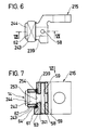
- FIG. 6 the third embodiment in side view according to arrow VI in FIG. 7
- FIG. 7 shows a section along line VII-VII in FIG. 6.
- a plurality of cylinder liners 2 are embedded in a row in a housing 1, only one of which is visible due to the cut position.
- a pump piston 3 with the interposition of a roller tappet 4, which has a roller 5, is driven by a camshaft 6 against the pump delivery pressure and the force of a spring 7 for its axial movement forming the working stroke.
- a suction chamber 8 is created, which is assigned to the pump elements formed from cylinder liners 2 and pump pistons 3.
- a control slide 9 is axially displaceable in the recesses of the cylinder liners 2.
- the suction chamber 8 is closed at the longitudinal ends by end shields 11, one of which is shown in plan view and in which a rotating shaft 12 arranged in the suction chamber 8 is mounted.
- a transverse groove 13 into which an adjusting bolt 14 of a fastening part designed as a rider 15 engages, which is connected to the rotating shaft 12 by screwing.
- connection bores 16 to the suction chamber 8, one of which is shown.
- a pressure line (not shown) which ends at an injection nozzle on the engine.
- the pump piston 3 there is a blind bore 22, which ends at the end face and opens into the pump working chamber 18, and a transverse bore 23, which opens into oblique grooves 24, each of which has a side facing away from one another in the outer surface of the pump piston 3.
- These oblique grooves 24 end at the bottom in counterbores 20 and interact with radial bores 25 of the control slide 9.
- control slide 9 So that the control slide 9 is secured against rotation during its axial displacement on the pump piston 3 and an exact assignment of the oblique grooves 24 to the radial bores 25 is ensured, the control slide 9 has a nose 26 with which it engages in a longitudinal groove 27 of the cylinder liner 2 .
- the pump piston 3 has flats 28 on its lower section, on which a bush 31 known to be rotatable by a control rod 29 engages, so that an axial displacement of the control rod 29 rotates the pump piston 3 and thus changes the assignment of the oblique grooves 24 to the radial bores 25 causes.
- the fuel supply to the suction chamber 8 takes place via the longitudinal groove 27 from an inflow channel 33 which runs in a pipe 34 arranged in the housing 1 and which has branch openings 35 towards the longitudinal grooves 27.
- This fuel injection pump works as follows: Towards the end of the suction stroke or in its UT position of the pump piston 3, fuel flows through the oblique grooves 24, the transverse bore 23 and the blind bore 22 and also through the suction bore 32 into the pump work chamber 18 and fills it up. As soon as, after the camshaft 6 has been rotated further, the roller tappet 4 is pushed upwards over the roller 5, the pump piston 3 displaces fuel from the pump work chamber 18. As long as the oblique grooves 24 with the blind holes 20 are completely immersed in the control slide 9, the delivery takes place from the pump work space 18 via the path described back to the suction space 8, initially also one certain amount is displaced back through the suction bore 32.
- the start of spraying is determined by the axial position of the control slide 9, which in turn is effected by the rotating shaft 12 or the slide 15 with adjusting bolts 14.
- This start of injection or the end of injection must correspond for the pump elements consisting of a row.
- the angled rider 15, 115, 215 is clamped to the torsion shaft 12, 112 via a screw bolt 36, between the rider 15, 115 and the rotating shaft 12, 112 a spacer 37 and between the head of the bolt 36 and the rider 15, 115 a washer 38 is arranged.
- the torsion shaft, the bolt and the washers are not shown.
- the spacer 37 is selected in the thickness so that the individual adjustment bolts 14 or control slide 9 can be adjusted to one another in their basic position.
- a mounting hole 39, 139, 239 is arranged on the rider 15, 115, 215, in which the adjusting bolt 14 is fastened with a holding pin 41, 141, 241.
- the adjustment bolt 14 also has a cylindrical pin 42, 142, 242, on which a slide shoe 43, 143, 243 is mounted and guided on the easily rotatable and with little axial play, this cylindrical pin being held by a head 44, 144, 244 in it Length is limited, which also serves as an axial stop of the slide shoe 43, 143, 243.
- the sliding shoe 43 is permanently connected to the rider 15.
- the holding pin 41 here has a smaller diameter than the cylindrical pin 42 on which the slide shoe 43 is mounted.
- the retaining pin 41 is riveted, a step surface 53 being in direct contact with a corresponding surface 54 of the rider 15. This surface 54 also serves for the axial guidance of the slide shoe 43.
- the head 44 of the adjusting bolt 14 has two flats 55, the remaining edge 56 of the head, in cooperation with the end face 46 of the sliding block 43, serving as an axial guide for the sliding block 43.
- strip-shaped elevations 57 are arranged, the inner surfaces of which lie opposite the flats 55 and delimit with them a gap 58, the width of which determines the possible rotation of the slide shoe 43 on the cylindrical pin 42.
- the rotation should be limited to about + - 5 degrees.
- the head 144 is flattened laterally up to a remaining bar, so that, however, protrusions 45 projecting beyond the diameter of the cylindrical pin 142 remain, which engage behind the slide shoe 143 on its end face 146 facing the pump piston .
- a collar 47 which the other end face of the slide shoe 143 faces and against which this end face also bears.
- two widenings 49 are provided in the central bore 48 of the slide shoe 143, which are somewhat larger than the projections 45, but so small that the radial guidance of the bore 48 on the Pin 142 is not affected.
- the projections 45 are pushed through the widenings 49, after which the sliding block is 90 degrees on the Pin 142 is rotated so that a type of bayonet connection is created with axial guidance of the sliding block 143, in which the projections 45 interact with the end face 146 of the sliding block 143.
- a locking pin 52 is inserted into a bore 51 which penetrates the adjusting bolt 14 and the sliding shoe 43, the ends of which are bent in order to prevent the pin 52 from falling out.
- the holding pin 41 is hard-soldered in the mounting hole 39.
- the slide shoe 43 can be replaced after removing the locking pin 52 and rotating it by 90 degrees, which can be advantageous if either there is a corresponding wear on the working surface of the slide shoe or if a slide shoe with other radial dimensions is to be used.
- the adjusting bolt 14 is detachably anchored in the fastening bore 239 of the slide 215.
- a cross pin 58 is provided, which is arranged in a continuous bore 59, which passes through the holding pin 241 and corresponding sections of the slide 215 for receiving the cross pin 58.
- a washer 61 is arranged between the step surface 253 of the adjustment bolt 14 and the surface 254 on the slide 215 opposite it, on which the end face of the sliding block 243 is also supported.
Landscapes
- Engineering & Computer Science (AREA)
- Chemical & Material Sciences (AREA)
- Combustion & Propulsion (AREA)
- Mechanical Engineering (AREA)
- General Engineering & Computer Science (AREA)
- Fuel-Injection Apparatus (AREA)
Applications Claiming Priority (2)
| Application Number | Priority Date | Filing Date | Title |
|---|---|---|---|
| DE3724662 | 1987-07-25 | ||
| DE19873724662 DE3724662A1 (de) | 1987-03-10 | 1987-07-25 | Kraftstoffeinspritzpumpe fuer brennkraftmaschinen |
Publications (3)
| Publication Number | Publication Date |
|---|---|
| EP0301222A2 true EP0301222A2 (fr) | 1989-02-01 |
| EP0301222A3 EP0301222A3 (en) | 1990-02-07 |
| EP0301222B1 EP0301222B1 (fr) | 1992-05-06 |
Family
ID=6332346
Family Applications (1)
| Application Number | Title | Priority Date | Filing Date |
|---|---|---|---|
| EP88109629A Expired - Lifetime EP0301222B1 (fr) | 1987-07-25 | 1988-06-16 | Pompe d'injection de combustible pour moteurs à combustion interne |
Country Status (4)
| Country | Link |
|---|---|
| US (1) | US4840161A (fr) |
| EP (1) | EP0301222B1 (fr) |
| JP (1) | JPS6445959A (fr) |
| DE (1) | DE3870748D1 (fr) |
Families Citing this family (8)
| Publication number | Priority date | Publication date | Assignee | Title |
|---|---|---|---|---|
| DE3811845A1 (de) * | 1988-04-08 | 1989-10-19 | Voest Alpine Automotive | Pumpeduese fuer dieselmotoren |
| DE3813320A1 (de) * | 1988-04-08 | 1989-10-19 | Voest Alpine Automotive | Pumpenduese fuer dieselmotoren |
| DE4041656A1 (de) * | 1990-12-22 | 1992-07-02 | Bosch Gmbh Robert | Kraftstoffeinspritzpumpe fuer brennkraftmaschinen |
| DE4143040C1 (fr) * | 1991-12-24 | 1993-07-08 | Robert Bosch Gmbh, 7000 Stuttgart, De | |
| JPH10231763A (ja) * | 1997-02-18 | 1998-09-02 | Zexel Corp | 燃料噴射ポンプ |
| DE19734196A1 (de) * | 1997-08-07 | 1999-02-11 | Hatz Motoren | Regelvorrichtung sowie Verfahren zu deren Herstellung |
| JP4467469B2 (ja) * | 2005-06-08 | 2010-05-26 | ボッシュ株式会社 | 燃料供給用ポンプ及びタペット構造体 |
| DE102007034036A1 (de) * | 2007-07-20 | 2009-01-22 | Robert Bosch Gmbh | Kraftstoffhochdruckpumpe mit Rollenstößel |
Family Cites Families (16)
| Publication number | Priority date | Publication date | Assignee | Title |
|---|---|---|---|---|
| DE1526725C3 (de) * | 1966-08-01 | 1973-10-25 | L'orange Kg, 7000 Stuttgart | Mehrzylinder Kraftstoffeinspntz pumpe |
| US3712763A (en) * | 1970-09-18 | 1973-01-23 | Caterpillar Tractor Co | Sleeve metering collar adjusting lever |
| DE3105738C2 (de) * | 1981-02-17 | 1983-01-20 | Daimler-Benz Ag, 7000 Stuttgart | Vorrichtung zur Nacheinstellung des Förderbeginns einer Einspritzpumpe für eine Brennkraftmaschine |
| JPS5888468A (ja) * | 1981-11-24 | 1983-05-26 | Nissan Motor Co Ltd | 内燃機関の点火装置 |
| US4531492A (en) * | 1984-03-27 | 1985-07-30 | Caterpillar Tractor Co. | Fuel injection timing and governor control apparatus |
| US4541391A (en) * | 1984-03-27 | 1985-09-17 | Caterpillar Tractor Co. | Timing control for fuel injection apparatus |
| JPS6114743U (ja) * | 1984-06-29 | 1986-01-28 | 株式会社ボッシュオートモーティブ システム | 燃料噴射装置 |
| DE3435987A1 (de) * | 1984-10-01 | 1986-04-10 | Robert Bosch Gmbh, 7000 Stuttgart | Kraftstoffeinspritzpumpe fuer brennkraftmaschinen |
| JPS61123756A (ja) * | 1984-11-16 | 1986-06-11 | Diesel Kiki Co Ltd | 燃料噴射ポンプ |
| DE3447375A1 (de) * | 1984-12-24 | 1986-07-03 | Robert Bosch Gmbh, 7000 Stuttgart | Kraftstoffeinspritzpumpe fuer brennkraftmaschinen |
| DE3447374A1 (de) * | 1984-12-24 | 1986-07-10 | Robert Bosch Gmbh, 7000 Stuttgart | Kraftstoffeinspritzpumpe fuer brennkraftmaschinen |
| DE3522451A1 (de) * | 1985-06-22 | 1987-01-02 | Bosch Gmbh Robert | Kraftstoffeinspritzpumpe fuer brennkraftmaschinen |
| DE3546222A1 (de) * | 1985-12-27 | 1987-07-02 | Bosch Gmbh Robert | Kraftstoffeinspritzpumpe fuer brennkraftmaschinen |
| DE3707646A1 (de) * | 1986-03-24 | 1987-10-08 | Bosch Gmbh Robert | Kraftstoffeinspritzpumpe fuer brennkraftmaschinen |
| US4737086A (en) * | 1986-05-27 | 1988-04-12 | Diesel Kiki Co., Ltd. | Fuel injection pump having variable prestroke mechanism |
| DE3644147A1 (de) * | 1986-12-23 | 1988-07-07 | Bosch Gmbh Robert | Kraftstoffeinspritzpumpe fuer brennkraftmaschinen |
-
1988
- 1988-06-16 EP EP88109629A patent/EP0301222B1/fr not_active Expired - Lifetime
- 1988-06-16 DE DE8888109629T patent/DE3870748D1/de not_active Expired - Lifetime
- 1988-06-29 US US07/213,044 patent/US4840161A/en not_active Expired - Fee Related
- 1988-07-25 JP JP63183735A patent/JPS6445959A/ja active Pending
Also Published As
| Publication number | Publication date |
|---|---|
| DE3870748D1 (de) | 1992-06-11 |
| EP0301222B1 (fr) | 1992-05-06 |
| JPS6445959A (en) | 1989-02-20 |
| US4840161A (en) | 1989-06-20 |
| EP0301222A3 (en) | 1990-02-07 |
Similar Documents
| Publication | Publication Date | Title |
|---|---|---|
| DE3590194C2 (de) | Brennstoff-Einspritzpumpe | |
| EP0335083B1 (fr) | Dispositif de déplacement angulaire relatif entre deux arbres en liaison d'entraînement | |
| DE4227853C2 (de) | Kraftstoffeinspritzpumpe für Brennkraftmaschinen | |
| DE4210143C2 (de) | Ventilantrieb für eine Brennkraftmaschine | |
| DE69716381T2 (de) | Ventilsteuerungsvorrichtung für eine Brennkraftmaschine | |
| DE4237777C2 (de) | Ventilbetätigungseinrichtung | |
| EP0301222B1 (fr) | Pompe d'injection de combustible pour moteurs à combustion interne | |
| DE3326973C2 (fr) | ||
| EP0185914B1 (fr) | Pompe d'injection de carburant pour moteurs à combustion interne | |
| DE3911160C2 (de) | Kraftstoffeinspritzpumpe für Brennkraftmaschinen | |
| DE3201011C2 (fr) | ||
| EP0207283A2 (fr) | Pompe d'injection de combustible pour moteurs à combustion interne | |
| DE3718499C2 (de) | Rotationsverteiler-Kraftstoffeinspritzpumpe | |
| EP0313865B1 (fr) | Pompe d'injection de combustible pour moteurs à combustion interne | |
| DE3724409A1 (de) | Kraftstoffeinspritzpumpe fuer brennkraftmaschinen | |
| EP0262167B1 (fr) | Pompe d'injection de carburant pour moteurs a combustion interne | |
| EP0757174A2 (fr) | Procédé de changement de l'avance d'une pompe d'injection de carburant et pompe d'injection de carburant | |
| EP0261155B1 (fr) | Pompe d'injection de carburant pour moteurs a combustion interne | |
| DE3138640C2 (fr) | ||
| DE3724662A1 (de) | Kraftstoffeinspritzpumpe fuer brennkraftmaschinen | |
| WO1986005843A1 (fr) | Pompe d'injection de carburant | |
| DE4041503C2 (de) | Kraftstoffeinspritzpumpe für Brennkraftmaschinen | |
| AT407427B (de) | Kraftstoffeinspritzpumpe für brennkraftmaschinen | |
| DE3320981C2 (fr) | ||
| EP0172370B1 (fr) | Pompe d'injection de combustible pour un moteur à combustion interne |
Legal Events
| Date | Code | Title | Description |
|---|---|---|---|
| PUAI | Public reference made under article 153(3) epc to a published international application that has entered the european phase |
Free format text: ORIGINAL CODE: 0009012 |
|
| AK | Designated contracting states |
Kind code of ref document: A2 Designated state(s): DE FR GB IT |
|
| PUAL | Search report despatched |
Free format text: ORIGINAL CODE: 0009013 |
|
| AK | Designated contracting states |
Kind code of ref document: A3 Designated state(s): DE FR GB IT |
|
| RHK1 | Main classification (correction) |
Ipc: F02M 59/24 |
|
| 17P | Request for examination filed |
Effective date: 19900703 |
|
| 17Q | First examination report despatched |
Effective date: 19910211 |
|
| RAP3 | Party data changed (applicant data changed or rights of an application transferred) |
Owner name: ROBERT BOSCH GMBH |
|
| GRAA | (expected) grant |
Free format text: ORIGINAL CODE: 0009210 |
|
| AK | Designated contracting states |
Kind code of ref document: B1 Designated state(s): DE FR GB IT |
|
| REF | Corresponds to: |
Ref document number: 3870748 Country of ref document: DE Date of ref document: 19920611 |
|
| GBT | Gb: translation of ep patent filed (gb section 77(6)(a)/1977) | ||
| PGFP | Annual fee paid to national office [announced via postgrant information from national office to epo] |
Ref country code: FR Payment date: 19920629 Year of fee payment: 5 |
|
| ET | Fr: translation filed | ||
| ITF | It: translation for a ep patent filed | ||
| PLBE | No opposition filed within time limit |
Free format text: ORIGINAL CODE: 0009261 |
|
| STAA | Information on the status of an ep patent application or granted ep patent |
Free format text: STATUS: NO OPPOSITION FILED WITHIN TIME LIMIT |
|
| 26N | No opposition filed | ||
| PGFP | Annual fee paid to national office [announced via postgrant information from national office to epo] |
Ref country code: GB Payment date: 19930604 Year of fee payment: 6 |
|
| PGFP | Annual fee paid to national office [announced via postgrant information from national office to epo] |
Ref country code: DE Payment date: 19930825 Year of fee payment: 6 |
|
| PG25 | Lapsed in a contracting state [announced via postgrant information from national office to epo] |
Ref country code: FR Effective date: 19940228 |
|
| REG | Reference to a national code |
Ref country code: FR Ref legal event code: ST |
|
| PG25 | Lapsed in a contracting state [announced via postgrant information from national office to epo] |
Ref country code: GB Effective date: 19940616 |
|
| GBPC | Gb: european patent ceased through non-payment of renewal fee |
Effective date: 19940616 |
|
| PG25 | Lapsed in a contracting state [announced via postgrant information from national office to epo] |
Ref country code: DE Effective date: 19950301 |
|
| PG25 | Lapsed in a contracting state [announced via postgrant information from national office to epo] |
Ref country code: IT Free format text: LAPSE BECAUSE OF NON-PAYMENT OF DUE FEES;WARNING: LAPSES OF ITALIAN PATENTS WITH EFFECTIVE DATE BEFORE 2007 MAY HAVE OCCURRED AT ANY TIME BEFORE 2007. THE CORRECT EFFECTIVE DATE MAY BE DIFFERENT FROM THE ONE RECORDED. Effective date: 20050616 |
|
| PGFP | Annual fee paid to national office [announced via postgrant information from national office to epo] |
Ref country code: IT Payment date: 20070523 Year of fee payment: 20 |
|
| PGRI | Patent reinstated in contracting state [announced from national office to epo] |
Ref country code: IT Effective date: 20091201 |