EP0301324A1 - Serrure avec un mécanisme de fermeture qui peut être libéré par une carte codée - Google Patents
Serrure avec un mécanisme de fermeture qui peut être libéré par une carte codée Download PDFInfo
- Publication number
- EP0301324A1 EP0301324A1 EP19880111289 EP88111289A EP0301324A1 EP 0301324 A1 EP0301324 A1 EP 0301324A1 EP 19880111289 EP19880111289 EP 19880111289 EP 88111289 A EP88111289 A EP 88111289A EP 0301324 A1 EP0301324 A1 EP 0301324A1
- Authority
- EP
- European Patent Office
- Prior art keywords
- card
- lock
- slide
- bolt
- lock according
- Prior art date
- Legal status (The legal status is an assumption and is not a legal conclusion. Google has not performed a legal analysis and makes no representation as to the accuracy of the status listed.)
- Granted
Links
- 238000003780 insertion Methods 0.000 claims abstract description 25
- 230000037431 insertion Effects 0.000 claims abstract description 25
- 230000033001 locomotion Effects 0.000 claims description 18
- 238000003287 bathing Methods 0.000 claims description 12
- 238000006073 displacement reaction Methods 0.000 claims description 8
- 230000006835 compression Effects 0.000 claims description 4
- 238000007906 compression Methods 0.000 claims description 4
- 230000009182 swimming Effects 0.000 abstract description 2
- 230000000903 blocking effect Effects 0.000 description 5
- 230000008878 coupling Effects 0.000 description 5
- 238000010168 coupling process Methods 0.000 description 5
- 238000005859 coupling reaction Methods 0.000 description 5
- 230000000694 effects Effects 0.000 description 4
- 238000010276 construction Methods 0.000 description 2
- 238000000151 deposition Methods 0.000 description 1
- 238000011161 development Methods 0.000 description 1
- 230000018109 developmental process Effects 0.000 description 1
- 239000000499 gel Substances 0.000 description 1
- 230000001771 impaired effect Effects 0.000 description 1
- 230000007257 malfunction Effects 0.000 description 1
- 239000000463 material Substances 0.000 description 1
- 238000000034 method Methods 0.000 description 1
- 230000002093 peripheral effect Effects 0.000 description 1
- 230000001960 triggered effect Effects 0.000 description 1
Images


Classifications
-
- G—PHYSICS
- G07—CHECKING-DEVICES
- G07F—COIN-FREED OR LIKE APPARATUS
- G07F7/00—Mechanisms actuated by objects other than coins to free or to actuate vending, hiring, coin or paper currency dispensing or refunding apparatus
- G07F7/06—Mechanisms actuated by objects other than coins to free or to actuate vending, hiring, coin or paper currency dispensing or refunding apparatus by returnable containers, i.e. reverse vending systems in which a user is rewarded for returning a container that serves as a token of value, e.g. bottles
- G07F7/0618—Mechanisms actuated by objects other than coins to free or to actuate vending, hiring, coin or paper currency dispensing or refunding apparatus by returnable containers, i.e. reverse vending systems in which a user is rewarded for returning a container that serves as a token of value, e.g. bottles by carts
- G07F7/0672—Special lock-activating tokens, serving as replacement of a payment or of a coin
- G07F7/0681—Special lock-activating tokens, serving as replacement of a payment or of a coin in which a card, pay-card or card-like object is used as the special token required to get permission or activate the lock to use the trolley or cart
-
- E—FIXED CONSTRUCTIONS
- E05—LOCKS; KEYS; WINDOW OR DOOR FITTINGS; SAFES
- E05B—LOCKS; ACCESSORIES THEREFOR; HANDCUFFS
- E05B13/00—Devices preventing the key or the handle or both from being used
-
- E—FIXED CONSTRUCTIONS
- E05—LOCKS; KEYS; WINDOW OR DOOR FITTINGS; SAFES
- E05B—LOCKS; ACCESSORIES THEREFOR; HANDCUFFS
- E05B35/00—Locks for use with special keys or a plurality of keys ; keys therefor
- E05B35/007—Locks for use with special keys or a plurality of keys ; keys therefor the key being a card, e.g. perforated, or the like
-
- G—PHYSICS
- G07—CHECKING-DEVICES
- G07F—COIN-FREED OR LIKE APPARATUS
- G07F17/00—Coin-freed apparatus for hiring articles; Coin-freed facilities or services
- G07F17/14—Coin-freed apparatus for hiring articles; Coin-freed facilities or services for fastenings for doors; for turnstiles
-
- G—PHYSICS
- G07—CHECKING-DEVICES
- G07F—COIN-FREED OR LIKE APPARATUS
- G07F7/00—Mechanisms actuated by objects other than coins to free or to actuate vending, hiring, coin or paper currency dispensing or refunding apparatus
-
- Y—GENERAL TAGGING OF NEW TECHNOLOGICAL DEVELOPMENTS; GENERAL TAGGING OF CROSS-SECTIONAL TECHNOLOGIES SPANNING OVER SEVERAL SECTIONS OF THE IPC; TECHNICAL SUBJECTS COVERED BY FORMER USPC CROSS-REFERENCE ART COLLECTIONS [XRACs] AND DIGESTS
- Y10—TECHNICAL SUBJECTS COVERED BY FORMER USPC
- Y10S—TECHNICAL SUBJECTS COVERED BY FORMER USPC CROSS-REFERENCE ART COLLECTIONS [XRACs] AND DIGESTS
- Y10S70/00—Locks
- Y10S70/41—Coin-controlled
-
- Y—GENERAL TAGGING OF NEW TECHNOLOGICAL DEVELOPMENTS; GENERAL TAGGING OF CROSS-SECTIONAL TECHNOLOGIES SPANNING OVER SEVERAL SECTIONS OF THE IPC; TECHNICAL SUBJECTS COVERED BY FORMER USPC CROSS-REFERENCE ART COLLECTIONS [XRACs] AND DIGESTS
- Y10—TECHNICAL SUBJECTS COVERED BY FORMER USPC
- Y10T—TECHNICAL SUBJECTS COVERED BY FORMER US CLASSIFICATION
- Y10T70/00—Locks
- Y10T70/70—Operating mechanism
- Y10T70/7051—Using a powered device [e.g., motor]
- Y10T70/7057—Permanent magnet
-
- Y—GENERAL TAGGING OF NEW TECHNOLOGICAL DEVELOPMENTS; GENERAL TAGGING OF CROSS-SECTIONAL TECHNOLOGIES SPANNING OVER SEVERAL SECTIONS OF THE IPC; TECHNICAL SUBJECTS COVERED BY FORMER USPC CROSS-REFERENCE ART COLLECTIONS [XRACs] AND DIGESTS
- Y10—TECHNICAL SUBJECTS COVERED BY FORMER USPC
- Y10T—TECHNICAL SUBJECTS COVERED BY FORMER US CLASSIFICATION
- Y10T70/00—Locks
- Y10T70/70—Operating mechanism
- Y10T70/7441—Key
- Y10T70/778—Operating elements
- Y10T70/7791—Keys
- Y10T70/7904—Magnetic features
Definitions
- the invention relates to a lock according to the preamble of claim 1.
- Such a lock is known from US Pat. No. 4,572,348, it being possible to lock the bolt by means of the key after inserting a coded card into the card insertion slot. In the locked position of the bolt, the key can then be removed, while the card remains in the lock fastened on the inside of the locker. The card is such that, when the latch is closed, a card scanning magnetic pin emerges from its position blocking the latch from being closed.
- Such a lock allows the user of a locker to lock it again after closing the bolt. This can lead to thoughtlessness or ignorance, after the locker has been used, the bolt is locked with the door open or closed and the key removed to pass the curfew.
- the object on which the invention is based is to provide a lock of the type in question of abuse-proof, user-friendly construction in such a way that operating errors are largely eliminated.
- each locking of the bolt down to the key withdrawal position is the first locking after inserting the card.
- the card insertion slot is now located on a slide which can be displaced together with the preliminary movement of the bolt.
- the latter is the carrier of the cam, which can be displaced from the front edge of the card, of the supplementary slide spring-loaded against the card insertion direction.
- the card scanning magnetic pen which is movable transversely to its direction of displacement, is controlled in such a way that it does not hinder the advancement of the slider and thus the latch. If, on the other hand, an incorrect card is used, this card scanning magnetic pin moves into a blocking position and blocks the correct closing. After a certain closing path has been covered, the cam is driven, as mentioned at the beginning.
- the modulation is made possible in a simple manner in that the cam is seated at the free end of the rocker which is mounted in the slide and is spring-loaded on the cam side by a compression spring in the direction of the card insertion slot. This represents part of the add-on slide.
- the lock is designed so that the bolt can be brought into its locking position either after inserting the card or after inserting a coin.
- Falls z. B. in a bathing establishment from the card issue the corresponding locking function can in a known manner by depositing coins to take the card during a bathing stay from the castle and to bring this into the closed position by means of the coin in order to receive corresponding services within the bathing establishment by means of the card.
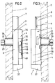
- the number 1 denotes a lock, which is attached to the inner surface of a door 2 of a locker.
- the lock has a lock case 3 lying directly on the door 2 and an attachment housing 4 associated therewith. From the bottom 5 of the lock case 3, lock case side walls 6 extend at right angles to it. In the upper area, the lock case 3 continues into a housing section 7 which is narrower than it, in which a coin plate 8 with a calibrated insertion slot 9 for a deposit coin 10 is located. In addition to actuation by means of the deposit coin, the lock can also be closed by means of a coded card 11.
- a horizontally displaceable bolt 12 is guided in the lock case 3. Whose bolt head 12 'passes through a lock case side wall 6, while the bolt tail 12' is guided on a square pin 13 on the lock housing side.
- the bolt tail 12 ⁇ contains a figured locking recess 14 into which a locking tooth 15 of a one-armed tumbler pawl 16 extends to the bottom 5.
- Whose bearing 17 starts from the bottom 5 and extends above the bolt head 12 '.
- a leaf spring 18 loads the tumbler pawl 16 clockwise in such a way that its locking tooth 15 is supported on the toothed lower edge 14 'of the locking recess 14.
- the bolt tail 12 '' On the side facing away from the bottom 5, the bolt tail 12 '' is mounted around a pin 19, a one-armed rocker 21 loaded by a leaf spring 20 in a clockwise direction.
- the rocker 21 is limited in its rotation by a bolt-side stop 22.
- the rocker 21 is Carrier of a convertible support pin 23 reaching to the bottom 5. This is opposite a shoulder 24 of the bolt 12. The distance between the shoulder 24 and the support pin 23 is less than the diameter of the coin 10, so that the inserted coin is held on the bolt 12 as shown in broken lines in FIG. 7 and does not fall through.
- the bolt 12 is equipped with a slot 26 directed transversely to its displacement movement, into which a finger 27 of a crank arm 28 engages.
- the latter is seated in a rotationally fixed manner on the flattened end of a cylinder core 29.
- This is rotatably arranged in a cylinder lock 30, which is attached to a lock cover 31 indicated by dash-dotted lines in FIG. 7 and penetrates a hole in the door 2.
- the cylinder core 29 receives a key 32, which cannot be removed when the bolt 12 is closed.
- the locking tooth 15 of the tumbler pawl 16 is a carrier of a driving pin 33 which passes through a recess 34 of the lock case base 5 and protrudes into the top housing 4.
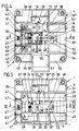
- the components of the top housing 4 are a lock front wall 35, the size of which corresponds to that of the lock case base 5 and from the lock front wall 35, in the direction of the lock case 3 facing housing walls 36, which in turn are supported on the lock case base 5.
- the lower housing wall 36 continues into a coin return compartment 37, which is connected to the lock case 3.
- the top housing 4 is provided with a horizontally extending longitudinal recess 38, which opens into the locking head 12 'opposite housing wall 36.
- the insertion end 39 ' is accordingly open to the corresponding housing wall 36.
- the lock front wall 35 forms a recess 40, which in turn is opaque to the insertion end 39 'of the slide 39 in its basic slide position.
- the slide 39 is held by two compression springs 41 arranged on either side of its longitudinal center, which are supported on the housing wall 36 adjacent to the locking head 12 '. For the rest, this basic position is limited.
- two stops 42 extend from the side of the slide 39 facing the lock front wall 35, which in turn are supported on counter-shoulders 43 of the lock front wall 35.
- the slide 39 is provided with a card insertion slot 44, which is designed in the form of a pocket for the form-fitting storage of the card 11 while supporting it in the area of all of its peripheral edges.
- the support on the rear card edge 11 ' is achieved by overflowing when inserting the card 11, side shoulders 45.
- the shoulders 45 are flanked by lateral guide strips 46 of the slider 39, which support the card side edges 11 ⁇ .
- the rounded card leading edge 11 11 is associated with a projection 47 of the slider 39 which extends between the stops 42.
- the card slot 44 continues into a handle opening 48.
- the slide 39 holds a supplementary slide 49, which is composed of two slide parts 50 and 51.
- the slide member 50 is T-shaped such that the T-bar 50 'is arranged to be movable in the horizontal direction to the slide 39.
- the T-beam 50 ' is provided with a guide slot 52 open on the edge, in which a slide-side guide pin 53 engages.
- the other re end of the T-beam 50 ' contains a bore 54 for the entry of the coupling pin 55 of the other slide part 51.
- a tension spring 56 attached to the guide pin 53 engages and loads the additional slide 49 against the forward displacement direction of the slide 39.
- the right angle to the T-bar 50 'extending T-web forms a control finger 50 ⁇ , which is provided with a bevel 57.
- the driver pin 33 of the tumbler pawl 16 projects into the movement path of this bevel 57.
- An elongated hole 58 extending in the longitudinal direction of the slide in a slide cover 59 is used to guide the aforementioned coupling pin 55.
- the latter covers the slide part 51, which is designed as a spring-loaded rocker in the direction of the card insertion slot 44.
- the rocker 51 has a window 60 through which an elongated slide projection 61 extends.
- the rocker 51 forms a cam 63 which extends through a longitudinal slot 62 of the slide 39 and which projects into the card insertion slot 44 and thus into the card insertion path.
- the longitudinal slot 62 also extends in the slide displacement direction or in the direction of movement of the additional slide.
- a blind hole 64 facing the slide cover 59 is machined, into which one end of a compression spring 65 is immersed, the other end of which is supported on the inner surface of the slide cover 59 and thus pivots the rocker 51 around the coupling pin 55 forming a hinge point .
- the cam 63 is shifted so far that it dips into an internal longitudinal groove 66 of the front wall 35 of the lock.
- the bottom of the longitudinal groove 66 merges with the corresponding housing wall 36 into a run-up slope 67, which accordingly lies in the range of motion of the cam 63.
- the height of the run-up slope 67 is such that the cam 63 can be moved completely out of the plane of the card insertion slot 44.
- a through hole 68 is machined in the middle of the slide projection 61 for receiving a card scanning magnetic pin 69 which can be moved transversely to the direction of displacement of the slide 39.
- a counter magnet 70 fixed in the lock case 3 extends in such a way that that the magnetic pin 69 is drawn into a recess 71 of the lock case base 5.
- the other end of the magnetic pin 69 ends with the facing wall of the card insertion slot 44, see FIG. 10.
- the pull-in magnet 70 is preceded by a repulsion magnet 72, the end face of which is at a level with that of the pull-in magnet 70 such that a forward displacement of the slider 39, the magnetic pin 69 can reach the repulsion magnet 72 without interference.
- the recess 71 merges into a locking edge 73.
- the free end of the slide projection 61 extends through a window 75 of the slide cover 59.
- a driver 74 extending from the bolt 12 protrudes into the window 75 in such a way that, after being released within the window 75, when closing, it moves against the corresponding window edge and thereby the slide 39 dragged along. In the basic position, the driver 74 prevents the slide 39 from being advanced.
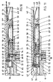
- the control finger 50 ⁇ has shifted from the position shown in FIG. 4 to the position shown in FIG. 5. As a result, it is located in the immediate vicinity of the driver pin 33 of the tumbler pawl 16.
- the locking operation can now be carried out by means of the key 32, the bolt 12 being dragged along in the pre-closing direction by means of the crank arm 28.
- the driver 74 starting from the latch 12, after covering a short distance, in turn engages the corresponding window edge of the window 75 of the slide cover 59 and thereby causes the slide 39 to be dragged along in the closing direction.
- the bevel 57 of the control finger 50 '' the driving pin 33 lifts the ratchet 15 from the path of movement of the figured edges of the locking recess 14 of the bolt 12, so that the preliminary movement is not impaired.
- the card scanning magnetic pin 69 is carried along during this preliminary movement. As soon as it reaches the area of the repulsion magnet 72, the magnetic pin 69 is moved inward in the direction of the front wall 35 of the lock by reaching through the card hole 76, as a result of which this magnetic pin 69 can pass through the locking edge 73.
- the cam 63 acts on the run-up slope 67 in connection with a pivoting of the rocker 51.
- the position according to FIGS. 8 and 13 is hereby achieved.
- the card rear edge 11 ' is then in the region of the recess 40 of the lock front wall 35 and allows the card 11 to be removed.
- the control finger 50' with its bevel 57 can drive pin 33 the tumbler pawl 16 cannot be reached.
- the ratchet tooth 15 moves in the blocking position to the corresponding edge of the blocking recess 14 and prevents the closing. Accordingly, the locker user cannot move the bolt fully into the pre-locking position in order to be able to remove the key afterwards. Rather, the user is alerted to removing the card from the card slot 44. If necessary, when the card 11 is reinserted, the latch can be pre-locked again, allowing intermediate use.
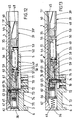
- the coin release control for the closing function which is connected in parallel to the card release control, can be carried out in such a way that a deposit coin 10 is inserted, which then falls into the position according to FIG. 7 and is supported on the pin 23 and the shoulder 24.
- the tumbler pawl 16 is then raised into a release position by the ratchet tooth 15, which allows the locking.
- the repulsion magnet 72 also displaces the card scanning magnet 69 into the release position. This closing in the manner e.g. be carried out if additional services are used within the bathing establishment by means of a correspondingly coded card during bath use.
- the deposit coin 10 falls into the coin return compartment 37 and can be removed there.
Landscapes
- Physics & Mathematics (AREA)
- General Physics & Mathematics (AREA)
- Lock And Its Accessories (AREA)
- Control Of Vending Devices And Auxiliary Devices For Vending Devices (AREA)
- Conveying Record Carriers (AREA)
- Coupling Device And Connection With Printed Circuit (AREA)
Priority Applications (1)
| Application Number | Priority Date | Filing Date | Title |
|---|---|---|---|
| AT88111289T ATE80746T1 (de) | 1987-07-25 | 1988-07-14 | Schloss mit durch einschub einer kodierten karte freizugebender schliessfunktion. |
Applications Claiming Priority (4)
| Application Number | Priority Date | Filing Date | Title |
|---|---|---|---|
| DE19873724711 DE3724711A1 (de) | 1987-07-25 | 1987-07-25 | Schloss mit durch einschub einer kodierten karte freizugebender schliessfunktion |
| DE3724711 | 1987-07-25 | ||
| DE19873724710 DE3724710A1 (de) | 1987-07-25 | 1987-07-25 | Schloss mit durch einschub einer kodierten karte freizugebender schliessfunktion |
| DE3724710 | 1987-07-25 |
Publications (2)
| Publication Number | Publication Date |
|---|---|
| EP0301324A1 true EP0301324A1 (fr) | 1989-02-01 |
| EP0301324B1 EP0301324B1 (fr) | 1992-09-16 |
Family
ID=25857959
Family Applications (1)
| Application Number | Title | Priority Date | Filing Date |
|---|---|---|---|
| EP19880111289 Expired - Lifetime EP0301324B1 (fr) | 1987-07-25 | 1988-07-14 | Serrure avec un mécanisme de fermeture qui peut être libéré par une carte codée |
Country Status (4)
| Country | Link |
|---|---|
| US (1) | US4918957A (fr) |
| EP (1) | EP0301324B1 (fr) |
| DE (1) | DE3874643D1 (fr) |
| ES (1) | ES2035176T3 (fr) |
Cited By (3)
| Publication number | Priority date | Publication date | Assignee | Title |
|---|---|---|---|---|
| EP0545233A1 (fr) * | 1991-12-06 | 1993-06-09 | Vendoret Holding S.A. | Dispositif de connexion de chariots d'achat ou à bagages |
| DE4341792A1 (de) * | 1993-06-04 | 1994-12-08 | Vendoret Holding Sa | Karte für ein Pfandschloß |
| FR2907485A1 (fr) * | 2006-10-24 | 2008-04-25 | Ceit Entpr S Soc Par Actions S | Dispositif antivol destine a equiper des cases pour bagages dans des moyens de transport en commun tels que train, bus |
Families Citing this family (17)
| Publication number | Priority date | Publication date | Assignee | Title |
|---|---|---|---|---|
| DE3819955A1 (de) * | 1988-06-11 | 1989-12-14 | Schulte Schlagbaum Ag | Schliesseinrichtung mit schluesselcodiertem druckeranschluss |
| DE4002092A1 (de) * | 1990-01-25 | 1991-08-01 | Schulte Schlagbaum Ag | Schloss mit durch einschieben einer bereichsweise magnetisierten schluesselkarte freizugebender schliessfunktion |
| ZA957405B (en) * | 1994-09-14 | 1996-04-17 | Diebold Inc | Electronic security system |
| US5573098A (en) * | 1995-03-01 | 1996-11-12 | Minnesota Lock, Inc. | Card-activated lock mechanism |
| DE19649444C2 (de) * | 1996-11-28 | 1999-07-15 | Sphinx Elektronik Gmbh | Schloß |
| US5905446A (en) * | 1997-03-24 | 1999-05-18 | Diebold, Incorporated | Electronic key system |
| DE69831311T2 (de) | 1998-05-08 | 2006-06-29 | Assa Ab | Kartenschloss |
| DE19832516A1 (de) * | 1998-07-20 | 2000-01-27 | Schulte Schlagbaum Ag | Schloß, insbesondere für eine Schließanlage |
| ES2229884B2 (es) * | 2003-03-20 | 2006-04-01 | Ojmar, S.A. | Cerradura de apertura con moneda, habilitada para su apertura con tarjeta. |
| US7080533B2 (en) * | 2003-05-23 | 2006-07-25 | Bruce Samuel Sedley | Lock and magnetically coded card |
| US6840071B2 (en) * | 2003-05-23 | 2005-01-11 | Bruce Samuel Sedley | Magnetic key-operated locks |
| US7131301B1 (en) * | 2005-09-23 | 2006-11-07 | Hsueh-Liang Chang | Locking device for a storage cabinet |
| US7377139B1 (en) * | 2006-11-06 | 2008-05-27 | Ping-Jan Yang | Specification cabinet lock |
| ES2339092B2 (es) * | 2008-10-13 | 2011-01-04 | Ojmar, S.A. | Cerradura que funciona indistintamente con tarjeta o moneda. |
| US9631920B2 (en) * | 2013-10-16 | 2017-04-25 | Google Inc. | Sensing system for verifying deadbolt engagement |
| WO2015087866A1 (fr) * | 2013-12-10 | 2015-06-18 | 日本電産サンキョー株式会社 | Lecteur de carte |
| TWI563161B (en) * | 2015-10-08 | 2016-12-21 | Delta Electronics Inc | A door with hiding locks and a container having the door |
Citations (2)
| Publication number | Priority date | Publication date | Assignee | Title |
|---|---|---|---|---|
| FR2465856A1 (fr) * | 1979-09-20 | 1981-03-27 | Snow Belle | Dispositif de verrouillage du pene de serrure commande par monnayeur |
| DE3242045A1 (de) * | 1982-11-13 | 1984-05-17 | Schulte-Schlagbaum Ag, 5620 Velbert | Schloss, insbesondere pfandschloss |
Family Cites Families (9)
| Publication number | Priority date | Publication date | Assignee | Title |
|---|---|---|---|---|
| US3015087A (en) * | 1955-07-26 | 1961-12-26 | Security Systems Inc | Security system |
| US3611763A (en) * | 1966-11-04 | 1971-10-12 | Boehme Inc H O | Magnetically operated mechanism and magnetic card |
| NL145015B (nl) * | 1968-12-16 | 1975-02-17 | Nederlanden Staat | Deurslot. |
| US3995460A (en) * | 1975-05-30 | 1976-12-07 | Sedley Bruce S | Magnetic card key operated door lock structure |
| US4133194A (en) * | 1976-12-02 | 1979-01-09 | Bruce S. Sedley | Magnetic key operated door lock |
| US4312198A (en) * | 1979-08-09 | 1982-01-26 | Sedley Bruce S | Magnetic key operated hotel door lock |
| US4644766A (en) * | 1983-10-04 | 1987-02-24 | Avant Incorporated | Non-electronic card-key actuated combination lock |
| JPS6141762U (ja) * | 1984-08-21 | 1986-03-17 | 俊彦 山下 | 錠前 |
| US4676083A (en) * | 1986-03-07 | 1987-06-30 | Sedley Bruce S | Locking mechanism with actuator |
-
1988
- 1988-07-14 DE DE8888111289T patent/DE3874643D1/de not_active Expired - Fee Related
- 1988-07-14 EP EP19880111289 patent/EP0301324B1/fr not_active Expired - Lifetime
- 1988-07-14 ES ES88111289T patent/ES2035176T3/es not_active Expired - Lifetime
- 1988-07-25 US US07/224,073 patent/US4918957A/en not_active Expired - Lifetime
Patent Citations (3)
| Publication number | Priority date | Publication date | Assignee | Title |
|---|---|---|---|---|
| FR2465856A1 (fr) * | 1979-09-20 | 1981-03-27 | Snow Belle | Dispositif de verrouillage du pene de serrure commande par monnayeur |
| DE3242045A1 (de) * | 1982-11-13 | 1984-05-17 | Schulte-Schlagbaum Ag, 5620 Velbert | Schloss, insbesondere pfandschloss |
| US4572348A (en) * | 1982-11-13 | 1986-02-25 | Schulte-Schlagbaum Aktiengesellschaft | Lock, particularly a coin-deposit lock |
Cited By (3)
| Publication number | Priority date | Publication date | Assignee | Title |
|---|---|---|---|---|
| EP0545233A1 (fr) * | 1991-12-06 | 1993-06-09 | Vendoret Holding S.A. | Dispositif de connexion de chariots d'achat ou à bagages |
| DE4341792A1 (de) * | 1993-06-04 | 1994-12-08 | Vendoret Holding Sa | Karte für ein Pfandschloß |
| FR2907485A1 (fr) * | 2006-10-24 | 2008-04-25 | Ceit Entpr S Soc Par Actions S | Dispositif antivol destine a equiper des cases pour bagages dans des moyens de transport en commun tels que train, bus |
Also Published As
| Publication number | Publication date |
|---|---|
| ES2035176T3 (es) | 1993-04-16 |
| DE3874643D1 (de) | 1992-10-22 |
| EP0301324B1 (fr) | 1992-09-16 |
| US4918957A (en) | 1990-04-24 |
Similar Documents
| Publication | Publication Date | Title |
|---|---|---|
| EP0301324B1 (fr) | Serrure avec un mécanisme de fermeture qui peut être libéré par une carte codée | |
| DE3242045C2 (fr) | ||
| DE19832516A1 (de) | Schloß, insbesondere für eine Schließanlage | |
| DE10194835B4 (de) | Hebelverschluss | |
| DE4019981A1 (de) | Verriegelungsanordnung fuer tueren | |
| DE4125448C2 (de) | Elektromotorischer Stellantrieb für eine zentrale Türverriegelungsanlage eines Kraftfahrzeugs | |
| DE2213668A1 (de) | Schloßanordnung, insbesondere für Schließfächer eines Tresorraumes od.dgl | |
| DE3124180C2 (fr) | ||
| DE10143123A1 (de) | Schloss, insbesondere Schrankschloss | |
| DE69831311T2 (de) | Kartenschloss | |
| DE29917091U1 (de) | Griffhebelverschluß zur Montage in einem rechteckigen Durchbruch in einer dünnen Wand, wie Blechschranktür | |
| DE2836486C2 (de) | Schloß mit nach Münzeinwurf zu betätigender Schließfunktion | |
| DE3407073A1 (de) | Tuerschloss mit riegel und falle | |
| EP0381820A2 (fr) | Crémone | |
| DE8902827U1 (de) | In Form eines Schildes ausgebildeter Türbeschlag | |
| DE2726908C2 (de) | Mit Zeituhr ausgestattetes Münz-PfandschloB | |
| DE3724711A1 (de) | Schloss mit durch einschub einer kodierten karte freizugebender schliessfunktion | |
| DE3724710A1 (de) | Schloss mit durch einschub einer kodierten karte freizugebender schliessfunktion | |
| EP1033461B1 (fr) | Serrure, notamment serrure à mortaise | |
| DE3431124A1 (de) | Vorrichtung zum schutz von video-recordern vor unbefugter benutzung | |
| EP0987659A1 (fr) | Magasin de stockage pour des porteurs de données en forme de carte | |
| DE3709408C2 (fr) | ||
| DE2839421A1 (de) | Schloss mit nach muenzeinwurf zu betaetigender schliessfunktion | |
| DE2238602A1 (de) | Schloss mit durch muenzeinwurf freizugebender schliessfunktion | |
| DE3447142C1 (de) | Türschloß mit zwei Schließzylindern |
Legal Events
| Date | Code | Title | Description |
|---|---|---|---|
| PUAI | Public reference made under article 153(3) epc to a published international application that has entered the european phase |
Free format text: ORIGINAL CODE: 0009012 |
|
| AK | Designated contracting states |
Kind code of ref document: A1 Designated state(s): AT BE CH DE ES FR GB GR IT LI LU NL SE |
|
| 17P | Request for examination filed |
Effective date: 19881222 |
|
| 17Q | First examination report despatched |
Effective date: 19911106 |
|
| GRAA | (expected) grant |
Free format text: ORIGINAL CODE: 0009210 |
|
| AK | Designated contracting states |
Kind code of ref document: B1 Designated state(s): AT BE CH DE ES FR GB GR IT LI LU NL SE |
|
| PG25 | Lapsed in a contracting state [announced via postgrant information from national office to epo] |
Ref country code: SE Effective date: 19920916 Ref country code: NL Effective date: 19920916 Ref country code: GR Free format text: LAPSE BECAUSE OF FAILURE TO SUBMIT A TRANSLATION OF THE DESCRIPTION OR TO PAY THE FEE WITHIN THE PRESCRIBED TIME-LIMIT Effective date: 19920916 Ref country code: BE Effective date: 19920916 |
|
| REF | Corresponds to: |
Ref document number: 80746 Country of ref document: AT Date of ref document: 19921015 Kind code of ref document: T |
|
| ET | Fr: translation filed | ||
| REF | Corresponds to: |
Ref document number: 3874643 Country of ref document: DE Date of ref document: 19921022 |
|
| GBT | Gb: translation of ep patent filed (gb section 77(6)(a)/1977) | ||
| ITF | It: translation for a ep patent filed | ||
| NLV1 | Nl: lapsed or annulled due to failure to fulfill the requirements of art. 29p and 29m of the patents act | ||
| REG | Reference to a national code |
Ref country code: ES Ref legal event code: FG2A Ref document number: 2035176 Country of ref document: ES Kind code of ref document: T3 |
|
| PLBE | No opposition filed within time limit |
Free format text: ORIGINAL CODE: 0009261 |
|
| STAA | Information on the status of an ep patent application or granted ep patent |
Free format text: STATUS: NO OPPOSITION FILED WITHIN TIME LIMIT |
|
| PG25 | Lapsed in a contracting state [announced via postgrant information from national office to epo] |
Ref country code: LU Free format text: LAPSE BECAUSE OF NON-PAYMENT OF DUE FEES Effective date: 19930731 |
|
| 26N | No opposition filed | ||
| PGFP | Annual fee paid to national office [announced via postgrant information from national office to epo] |
Ref country code: CH Payment date: 19940713 Year of fee payment: 7 |
|
| PGFP | Annual fee paid to national office [announced via postgrant information from national office to epo] |
Ref country code: AT Payment date: 19940714 Year of fee payment: 7 |
|
| PGFP | Annual fee paid to national office [announced via postgrant information from national office to epo] |
Ref country code: ES Payment date: 19940730 Year of fee payment: 7 |
|
| PGFP | Annual fee paid to national office [announced via postgrant information from national office to epo] |
Ref country code: FR Payment date: 19950629 Year of fee payment: 8 |
|
| PGFP | Annual fee paid to national office [announced via postgrant information from national office to epo] |
Ref country code: GB Payment date: 19950703 Year of fee payment: 8 |
|
| PG25 | Lapsed in a contracting state [announced via postgrant information from national office to epo] |
Ref country code: AT Effective date: 19950714 |
|
| PG25 | Lapsed in a contracting state [announced via postgrant information from national office to epo] |
Ref country code: ES Free format text: LAPSE BECAUSE OF THE APPLICANT RENOUNCES Effective date: 19950715 |
|
| PG25 | Lapsed in a contracting state [announced via postgrant information from national office to epo] |
Ref country code: LI Effective date: 19950731 Ref country code: CH Effective date: 19950731 |
|
| REG | Reference to a national code |
Ref country code: CH Ref legal event code: PL |
|
| PG25 | Lapsed in a contracting state [announced via postgrant information from national office to epo] |
Ref country code: GB Effective date: 19960714 |
|
| GBPC | Gb: european patent ceased through non-payment of renewal fee |
Effective date: 19960714 |
|
| PG25 | Lapsed in a contracting state [announced via postgrant information from national office to epo] |
Ref country code: FR Effective date: 19970328 |
|
| REG | Reference to a national code |
Ref country code: FR Ref legal event code: ST |
|
| REG | Reference to a national code |
Ref country code: ES Ref legal event code: FD2A Effective date: 19991007 |
|
| PGFP | Annual fee paid to national office [announced via postgrant information from national office to epo] |
Ref country code: DE Payment date: 20030731 Year of fee payment: 16 |
|
| PG25 | Lapsed in a contracting state [announced via postgrant information from national office to epo] |
Ref country code: DE Free format text: LAPSE BECAUSE OF NON-PAYMENT OF DUE FEES Effective date: 20050201 |
|
| PG25 | Lapsed in a contracting state [announced via postgrant information from national office to epo] |
Ref country code: IT Free format text: LAPSE BECAUSE OF NON-PAYMENT OF DUE FEES;WARNING: LAPSES OF ITALIAN PATENTS WITH EFFECTIVE DATE BEFORE 2007 MAY HAVE OCCURRED AT ANY TIME BEFORE 2007. THE CORRECT EFFECTIVE DATE MAY BE DIFFERENT FROM THE ONE RECORDED. Effective date: 20050714 |