EP0301536A2 - Alliage de palladium comme catalyseur pour l'oxydation de l'hydrogène dans une atmosphère contenant de l'hydrogène et de l'oxygène - Google Patents
Alliage de palladium comme catalyseur pour l'oxydation de l'hydrogène dans une atmosphère contenant de l'hydrogène et de l'oxygène Download PDFInfo
- Publication number
- EP0301536A2 EP0301536A2 EP88112214A EP88112214A EP0301536A2 EP 0301536 A2 EP0301536 A2 EP 0301536A2 EP 88112214 A EP88112214 A EP 88112214A EP 88112214 A EP88112214 A EP 88112214A EP 0301536 A2 EP0301536 A2 EP 0301536A2
- Authority
- EP
- European Patent Office
- Prior art keywords
- hydrogen
- palladium alloy
- sheet
- catalyst chamber
- catalyst
- Prior art date
- Legal status (The legal status is an assumption and is not a legal conclusion. Google has not performed a legal analysis and makes no representation as to the accuracy of the status listed.)
- Granted
Links
Images


Classifications
-
- B—PERFORMING OPERATIONS; TRANSPORTING
- B01—PHYSICAL OR CHEMICAL PROCESSES OR APPARATUS IN GENERAL
- B01J—CHEMICAL OR PHYSICAL PROCESSES, e.g. CATALYSIS OR COLLOID CHEMISTRY; THEIR RELEVANT APPARATUS
- B01J23/00—Catalysts comprising metals or metal oxides or hydroxides, not provided for in group B01J21/00
- B01J23/70—Catalysts comprising metals or metal oxides or hydroxides, not provided for in group B01J21/00 of the iron group metals or copper
- B01J23/89—Catalysts comprising metals or metal oxides or hydroxides, not provided for in group B01J21/00 of the iron group metals or copper combined with noble metals
-
- C—CHEMISTRY; METALLURGY
- C01—INORGANIC CHEMISTRY
- C01B—NON-METALLIC ELEMENTS; COMPOUNDS THEREOF; METALLOIDS OR COMPOUNDS THEREOF NOT COVERED BY SUBCLASS C01C
- C01B5/00—Water
-
- C—CHEMISTRY; METALLURGY
- C22—METALLURGY; FERROUS OR NON-FERROUS ALLOYS; TREATMENT OF ALLOYS OR NON-FERROUS METALS
- C22C—ALLOYS
- C22C5/00—Alloys based on noble metals
- C22C5/04—Alloys based on a platinum group metal
-
- G—PHYSICS
- G21—NUCLEAR PHYSICS; NUCLEAR ENGINEERING
- G21C—NUCLEAR REACTORS
- G21C19/00—Arrangements for treating, for handling, or for facilitating the handling of, fuel or other materials which are used within the reactor, e.g. within its pressure vessel
- G21C19/28—Arrangements for introducing fluent material into the reactor core; Arrangements for removing fluent material from the reactor core
- G21C19/30—Arrangements for introducing fluent material into the reactor core; Arrangements for removing fluent material from the reactor core with continuous purification of circulating fluent material, e.g. by extraction of fission products deterioration or corrosion products, impurities, e.g. by cold traps
- G21C19/317—Recombination devices for radiolytic dissociation products
-
- Y—GENERAL TAGGING OF NEW TECHNOLOGICAL DEVELOPMENTS; GENERAL TAGGING OF CROSS-SECTIONAL TECHNOLOGIES SPANNING OVER SEVERAL SECTIONS OF THE IPC; TECHNICAL SUBJECTS COVERED BY FORMER USPC CROSS-REFERENCE ART COLLECTIONS [XRACs] AND DIGESTS
- Y02—TECHNOLOGIES OR APPLICATIONS FOR MITIGATION OR ADAPTATION AGAINST CLIMATE CHANGE
- Y02E—REDUCTION OF GREENHOUSE GAS [GHG] EMISSIONS, RELATED TO ENERGY GENERATION, TRANSMISSION OR DISTRIBUTION
- Y02E30/00—Energy generation of nuclear origin
- Y02E30/30—Nuclear fission reactors
Definitions
- the invention relates to a palladium alloy which serves as a catalyst for the oxidation of hydrogen in an atmosphere containing hydrogen and oxygen, and to a safety device for receiving the palladium alloy.
- Eliminating hydrogen from a gas mixture containing hydrogen and oxygen and therefore explosive is particularly important in the case of nuclear reactor accidents. Such gas mixtures can occur particularly in the case of meltdowns of light water reactors.
- a non-prepublished German patent application P 36 04 416.4-43 (PT 1.781 G) describes a device for removing hydrogen which can be used in the containment and in which metals are used to absorb the hydrogen, which have a high absorption capacity for hydrogen even at low hydrogen partial pressure Have gas mixture. To prevent oxidation, the metals are covered with a hydrogen-permeable protective layer. Palladium is also used as a protective layer. Palladiumbe Layered vanadium has proven to be a catalyst for the effective conversion of hydrogen to water.
- the object of the invention is to find catalysts with the shortest possible response time until the catalytic reaction. It is also important to develop catalysts that are insensitive to catalyst poisons such as chlorine, sulfur and carbon monoxide in the gas mixture.
- the catalytic conversion should be as high as possible even at temperatures around 100 ° C in order to avoid detonating gas reactions in the containment.
- the palladium alloy contains at least 80% by weight of Pd, a maximum of up to 19.9% by weight of a further metal from the 8th group of the periodic system, in particular Ni, and a maximum of 10% by weight of Cu.
- Pd palladium alloys of this type
- hydrogen can be oxidized in the presence of oxygen in the gas mixture at temperatures around 100 ° C. on the surface of the alloys.
- catalyst poisons such as chlorine, sulfur or carbon monoxide, the response time to the start of the reaction is only a few minutes.
- Palladium alloys with at least 89% by weight of Pd, a maximum of 10% by weight of Ni and a maximum of 1% by weight of Cu are preferred, claim 2.
- an alloy with 95% by weight of Pd, 4% by weight of Ni and 1% by weight of Cu has proven itself, claim 3 Alloys of this type catalyze the oxidation of hydrogen in gas mixtures which contain chlorine, sulfur compounds and carbon monoxide with very little delay. The reactions are reliable.
- a gas-tightly closed catalyst chamber which contains a sheet or a mesh made of the palladium alloy or a metallic carrier sheet coated with the palladium alloy.
- the sheet or mesh or carrier sheet is arranged in the catalyst chamber in such a way that after opening the chamber in the event of danger - that is, when hydrogen enters the gas atmosphere surrounding the catalyst chamber - hydrogen penetrates - it comes into contact with the gas atmosphere.
- the total catalyst surface available in the event of danger becomes so stipulated that the sheet, net or support sheet is not heated so high when it is heated during the reaction by absorbing the heat of reaction that the ignition temperature of the gas mixture is reached on the catalyst surface.
- a limit temperature is set for the catalyst surface, which is below the ignition temperature, and the minimum area required for sheet metal, mesh or carrier sheet is determined taking into account on the one hand the expected amount of hydrogen, which can penetrate the gas atmosphere to a maximum and which specifies the maximum heat of reaction that develops , and on the other hand, taking into account the possible heat emission from sheet metal, mesh or carrier sheet to the environment, the heat transfer between the catalyst surface and the gas atmosphere being particularly important.
- the sheet or net or carrier sheet are preferably housed in the catalyst chamber such that they extend into the environment after opening the catalyst chamber with the formation of a contact surface, claim 7. This is advantageously done under the action of gravity, claim 8, so that in the event of danger for Training the contact area no additional facilities are required.
- the sheet, mesh or carrier sheet are folded like a blind in the catalyst chamber and arranged so that they unfold under the action of gravity after opening the security container and quickly stretch out into the environment.
- the sheet or net or carrier sheet is also without additional Devices can then be automatically extended into the environment if they are wound inside the catalyst chamber like a roller blind and are arranged so that they roll out into the environment after opening the catalyst chamber under the action of the spring force.
- the catalytic effect of a palladium alloy which contained 9% by weight of Pd, 4% by weight of Ni, 1% by weight of Cu and was applied to both sides of an aluminum carrier plate, is investigated in a reaction chamber into which a realistic gas mixture adaptable to reactor accidents could be introduced .
- a reaction chamber In the reaction chamber, one or more support plates with a free, coated surface were each arranged in such a way that the two coated sides were accessible to the gas mixture contained in the reaction chamber.
- the reaction chamber which had a volume of 6.5 lt, had support plates with a total surface area of 240 cm 2 for the catalysis.
- Fig. 1 the pressure curve in the reaction chamber (I marked line) is shown after introducing hydrogen into a gas atmosphere which contained 1.3 bar air, 1.6 bar steam, 0.007 bar CO in partial pressures. In this gas atmosphere, 0.4 bar of H2 were introduced.
- the temperature profile in the coated carrier sheet (dashed line marked II) and the temperature curve in the vicinity of the coated carrier sheet in the reaction chamber, that is, the room temperature of the reaction chamber (dash-dotted chain marked III) are shown in FIG. 1.
- the temperature in the carrier sheet increases from 120 ° C within 1 minute to a maximum temperature of 260 ° C. The temperature quickly subsides after reaching this maximum temperature. After 4 minutes, the carrier plate reaches the initial temperature of 120 ° C again.
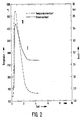
- FIG. 2 shows the course of the reaction of a catalytic oxidation of hydrogen for a palladium alloy which contains 90% by weight of Pd, Contains 9.5 wt% Ni, 0.5 wt% Cu.
- the palladium alloy is sputtered on both sides of an aluminum carrier plate.
- the carrier plate is 0.1 mm thick. A total of 80 cm2 catalyst surface are available for catalysis.
- FIG. 2 shows the pressure curve in the reaction chamber and the temperature curve in the carrier plate in the same way as in FIG. 1: I denotes the line for the pressure curve in the reaction chamber, II denotes the temperature curve in the carrier plate. 2, the temperature profile in the vicinity of the carrier plate has not been reproduced, but the heat in the reaction chamber is only slight here too. The heat generated during catalysis is absorbed and removed by the carrier plate.
- the reaction chamber contains a gas atmosphere with the following gas fractions (specified in partial pressures): air 1.3 bar, water vapor 1.6 bar, CO 0.005 bar. Hydrogen at 0.4 bar was introduced into the gas atmosphere.
- the catalytic reaction also begins in the palladium alloy used here immediately after the hydrogen has been introduced into the gas atmosphere.
- the temperature in the carrier plate also increases.
- the catalytic oxidation of the hydrogen leads to a drop in pressure, the pressure in the reaction chamber drops from about 3.4 to 3.1 bar.
- the temperature in the carrier plate increases rapidly from 120 ° C and rises within the first minute a maximum of about 240 ° C. It then falls again and returns to its initial value of 120 ° C after only 3 minutes.
- the hydrogen is completely converted into water vapor.
- a palladium alloy with 90% by weight Pd, 9.5% by weight Ni, 0.5% by weight Cu was used as the sheet (rolled foil).
- a separate carrier plate was not used.
- the dimensions of the sheet were 200 x 20 x 0.1 mm3. In the reaction chamber of 6.5 lt volume, a total of 80 cm2 catalyst surface was available.
- a gas mixture containing 1.3 bar of air, 0.005 bar of CO and 1.6 bar of water vapor was contained in the reaction chamber.
- the gas atmosphere was contaminated with traces of impurities from chlorine, water-soluble aerosols (silver and boron nitrate) and oil in order to create a state of the gas atmosphere that was as unfavorable for the catalytic reaction as could occur in the reactor containment vessel in the event of reactor accidents.
- the initial temperature in the sheet was 120 ° C.
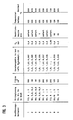
- Carrier sheets with a catalytically active total surface area of 120 cm2 were used in the reactor chamber. There was a gas atmosphere which contained 1.6 bar of air and 0.005 bar of carbon monoxide. In this gas atmosphere, 0.4 bar of H2 were introduced. The initial temperature in the carrier plate was 120 ° C.
- a Pd alloy with 94% by weight of Pd, 5% by weight of Ni and 1% by weight of Cu was vapor-deposited on both sides on an aluminum carrier plate.
- the thickness of the Pd alloy was 3000 ⁇ on both sides of the carrier sheet.
- a carrier sheet had the following dimensions: 200 x 30 x 0.1 mm3.
- a total of 240 cm 2 of catalyst surface area were available in this exemplary embodiment. It goes without saying that the larger the catalyst surface used within the reaction chamber, the quicker the catalytic reaction starts. However, the maximum permissible heat is essential for determining the catalyst surface up to the specified limit temperature below the ignition temperature of the gas mixture.
- the specific heat transfer (heat transfer coefficient in J / m2Ks) is also important.
- the aim should be to offer the gas atmosphere in the reactor containment as much catalyst surface as possible in the event of a malfunction and to do so as quickly as possible.
- the gas atmosphere present in the reaction chamber had the following composition in partial pressures: air 1.3 bar, steam 1.6 bar, CO 0.007 bar.
- the initial temperature in the carrier plate was 120 ° C.
- 0.4 bar of H2 were introduced.
- the catalytic reaction started without noticeable delay, the maximum temperature in the carrier plate was 280 ° C.
- a Pd alloy containing 94% by weight of Pd, 5% by weight of Ni, 1% by weight of Cu was applied on both sides to an aluminum carrier plate with a dimension of 145 ⁇ 28 ⁇ 0.1 mm 3.
- Support plates with a total catalyst surface area of 180 cm2 were used in the reaction chamber.
- the gas atmosphere in the reaction chamber had the following gas proportions in partial pressures: air 1.3 bar, water vapor 1.6 bar, CO 0.006 bar.
- the initial temperature in the carrier plate was 120 ° C. 0.4 bar of H2 were introduced.
- the Pd alloy with 9% by weight of Pd, 4% by weight of Ni, 1% by weight of Cu was evaporated on both sides onto a copper carrier plate.
- the reaction chamber had a surface area of 240 cm2 available. 0.08 bar of hydrogen (4% by volume) was introduced into the air atmosphere of 1.9 bar in the chamber.
- the initial temperature in the carrier plate was approximately 100 ° C.
- the reaction started immediately after introducing the hydrogen, the maximum temperature in the carrier plate was 130 ° C.
- FIG. 4 schematically shows a gas-tightly closed catalyst chamber 1 with a support sheet 2 folded like a louver and coated with a Pd alloy.
- the catalyst chamber is suspended on its top wall 3 on a bracket 4.
- the uppermost sheet metal parts 2a of the carrier sheets are fastened to an edge 6 in two chamber spaces 1a, 1b separated by an intermediate wall 5.
- the bracket 4 can be anchored, for example, on the ceiling of the reactor containment so that below the Kataly satorhunt 1 a free space for extending the support plate 2 remains after opening the catalyst chamber.
- the catalyst chamber 1 consists of aluminum walls 7, which are soldered to the top wall 3 and to one another.
- the soft solder is selected so that the catalyst chamber opens when a predetermined temperature occurs in the event of danger by softening the connecting seams on the aluminum walls 7 and falling apart of the walls and the support plate 2 is released.
- the carrier plate then extends under its own weight into the space below the catalyst chamber 1. The catalyst surface is brought into contact with the gas atmosphere.
- the carrier plate 2 is only used folded in the catalyst chamber. If a surface that is as flat as possible and rapidly unfolds is to be produced, it is expedient to connect the individual carrier plates to one another at their edges by means of hinges, so that the carrier plates joined to one another are easily movable relative to one another. Carrier plates connected with hinges are not shown in FIG. 4.
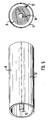
- FIG. 5 shows a barrel-shaped catalyst chamber 8 in which a carrier plate 9 coated with a Pd alloy is rolled up on a shaft 10 pretensioned like a spiral spring.
- a bottom flap 11 which is soft-soldered in the barrel-shaped catalyst chamber 8 in the same way as in the exemplary embodiment according to FIG. 4, the carrier plate 9 unrolls underneath Effect of the spring force in the environment and releases the catalyst surface for contact with the gas atmosphere created in the reactor containment. The catalytic oxidation of the hydrogen then begins within a few minutes.
- Both catalyst chambers 1 and 8 are filled with inert gas, for example argon, in the closed state.
- the inert gas is under pressure to prevent the ingress of foreign gas from the outside.
- the inert gas atmosphere contains 1 to 2% by volume of hydrogen.
- sheets or nets made of Pd alloys can also be used. If foils are used, care must be taken to extend them into the environment, for example by attaching a strip that weighs down the foil to the outer edge of the foil and that first lowers when the catalyst chamber is opened. Such a bar 12 is shown in FIG. 5.
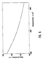
- the temperature increase in K is plotted over the minimum area for the catalyst surface in m 2, which occurs at most in the carrier plate in the case of the hydrogen drop assumed above.
- the temperature development in the carrier plate is determined by the thermal equilibrium between heat development due to the oxidation reaction and heat emission from the carrier plate to the environment.
- the maximum temperature in the catalyst surface decreases with increasing surface. With a surface area of 5000 m2, the maximum temperature increase remains below 300 K, ie at an initial temperature of The temperature in the carrier sheet rises to around 400 ° C. at 120 ° C. This temperature is far below the ignition temperature and gives a sufficient safety distance from the ignition temperature even under realistic conditions.
Landscapes
- Chemical & Material Sciences (AREA)
- Organic Chemistry (AREA)
- Engineering & Computer Science (AREA)
- Physics & Mathematics (AREA)
- Materials Engineering (AREA)
- Chemical Kinetics & Catalysis (AREA)
- Inorganic Chemistry (AREA)
- Plasma & Fusion (AREA)
- General Engineering & Computer Science (AREA)
- High Energy & Nuclear Physics (AREA)
- Mechanical Engineering (AREA)
- Metallurgy (AREA)
- Catalysts (AREA)
- Exhaust Gas Treatment By Means Of Catalyst (AREA)
Applications Claiming Priority (2)
| Application Number | Priority Date | Filing Date | Title |
|---|---|---|---|
| DE3725290 | 1987-07-30 | ||
| DE19873725290 DE3725290A1 (de) | 1987-07-30 | 1987-07-30 | Palladiumlegierung als katalysator zur oxidation von wasserstoff in wasserstoff und sauerstoff enthaltender atmosphaere |
Publications (3)
| Publication Number | Publication Date |
|---|---|
| EP0301536A2 true EP0301536A2 (fr) | 1989-02-01 |
| EP0301536A3 EP0301536A3 (fr) | 1993-07-28 |
| EP0301536B1 EP0301536B1 (fr) | 1997-09-10 |
Family
ID=6332725
Family Applications (1)
| Application Number | Title | Priority Date | Filing Date |
|---|---|---|---|
| EP88112214A Expired - Lifetime EP0301536B1 (fr) | 1987-07-30 | 1988-07-28 | Alliage de palladium comme catalyseur pour l'oxydation de l'hydrogène dans une atmosphère contenant de l'hydrogène et de l'oxygène |
Country Status (6)
| Country | Link |
|---|---|
| EP (1) | EP0301536B1 (fr) |
| JP (1) | JP2723544B2 (fr) |
| CA (1) | CA1314277C (fr) |
| DE (2) | DE3725290A1 (fr) |
| RU (1) | RU1782326C (fr) |
| SU (1) | SU1757445A3 (fr) |
Cited By (11)
| Publication number | Priority date | Publication date | Assignee | Title |
|---|---|---|---|---|
| EP0358912A1 (fr) * | 1988-08-04 | 1990-03-21 | Forschungszentrum Jülich Gmbh | Catalyseur constitué d'un système de couches métalliques pour l'élimination de l'hydrogène contenu dans un mélange gazeux |
| EP0436942A3 (en) * | 1990-01-08 | 1991-11-13 | Gesellschaft Fuer Reaktorsicherheit (Grs) Mbh | Device for removing hydrogen from hydrogen, oxygen and aerosol containing gaseous mixture |
| WO1991018398A1 (fr) * | 1990-05-11 | 1991-11-28 | Siemens Aktiengesellschaft | Dispositif pour la recombinaison de l'hydrogene et de l'oxygene et utilisation du dispositif |
| EP0467110A1 (fr) * | 1990-07-12 | 1992-01-22 | Forschungszentrum Jülich Gmbh | Catalyseur pour l'élimination de l'hydrogène d'une atmosphère contenant de l'hydrogène, de l'oxygène et de la vapeur |
| FR2666030A1 (fr) * | 1990-08-27 | 1992-02-28 | Commissariat Energie Atomique | Procede d'humidification d'un gaz et dispositif pour sa mise en óoeuvre. |
| EP0670183A1 (fr) * | 1993-11-11 | 1995-09-06 | GESELLSCHAFT FÜR ANLAGEN- UND REAKTORSICHERHEIT ( GRS) mbH | Procédé de préparation d'une couche catalytique de grande porosité à base d'un alliage au palladium ou au platine |
| DE19636555C1 (de) * | 1996-09-09 | 1998-01-15 | Siemens Ag | Verfahren und Einrichtung zur Einleitung einer Wasserstoff-Sauerstoff-Reaktion in einem Reaktor-Sicherheitsbehälter |
| EP0611126B1 (fr) * | 1993-02-10 | 1998-11-25 | Kemira Oy | Catalyseur d'hydrogénation pour la production du peroxyde d'hydrogène et procédé pour le préparer |
| US6054108A (en) * | 1996-09-09 | 2000-04-25 | Siemens Aktiengesellschaft | Catalyst system and recombination device for recombining hydrogen and oxygen, in particular for a nuclear power station and method for operating a catalyst system |
| WO2000030121A1 (fr) * | 1998-11-17 | 2000-05-25 | Forschungszentrum Jülich GmbH | Element catalyseur pour recombineur servant a eliminer efficacement l'eau provenant d'atmospheres polluees suite a un accident |
| WO2003099422A1 (fr) * | 2002-05-25 | 2003-12-04 | Forschungszentrum Jülich GmbH | Convertisseur de gaz pourvu d'un systeme catalyseur a activite adaptee |
Families Citing this family (11)
| Publication number | Priority date | Publication date | Assignee | Title |
|---|---|---|---|---|
| DE3909540A1 (de) * | 1989-03-22 | 1990-09-27 | Nis Ingenieurgesellschaft Mbh | Vorrichtung zur rekombination von wasserstoff aus einem wasserstoffhaltigen gasgemisch |
| EP0416143B1 (fr) * | 1989-09-04 | 1995-01-25 | Gesellschaft für Reaktorsicherheit (GRS) mbH | Dispositif d'élimination de l'hydrogène et dissolution des couches d'étanchement |
| DE4319973A1 (de) * | 1993-06-17 | 1995-02-16 | Forschungszentrum Juelich Gmbh | Katalysatoren zur Beseitigung von Wasserstoff aus einer Wasserstoff, Luft und Dampf enthaltenden Atmosphäre |
| DE59300692D1 (de) * | 1993-12-13 | 1995-11-16 | Anlagen Und Reaktorsicherheit | Vorrichtung zur Entfernung von freiem Wasserstoff aus einem Wasserstoff und Sauerstoff enthaltenden Gasgemisch. |
| RU2132885C1 (ru) * | 1995-08-08 | 1999-07-10 | Институт химии силикатов РАН | Состав композиции на основе палладия |
| JP2000098075A (ja) * | 1998-07-23 | 2000-04-07 | Toshiba Corp | 可燃性ガス除去装置 |
| DE19914814C1 (de) | 1999-03-31 | 2000-12-14 | Siemens Ag | Rekombinationseinrichtung und Verfahren zur katalytischen Rekombination von Wasserstoff und/oder Kohlenmonoxid mit Sauerstoff in einem Gasgemisch |
| DE102004052542B4 (de) * | 2004-11-13 | 2007-02-08 | Hauptmanns, Ulrich, Prof. Dr.-Ing. | Fahrzeugkomponente und Beschichtungsmaterial für eine Fahrzeugkomponente |
| CN100457935C (zh) * | 2005-11-09 | 2009-02-04 | 贵研铂业股份有限公司 | 回收铂催化剂用钯基合金及回收网 |
| DE102012220159B4 (de) * | 2012-11-06 | 2019-06-27 | Ersa Gmbh | Verfahren und Reinigungssystem zur Reinigung des Prozessgases in Lötanlagen und Lötabsaugsystemen |
| KR20150045032A (ko) | 2013-10-17 | 2015-04-28 | 한국원자력연구원 | 가연성 기체 연소 제어기 |
Family Cites Families (9)
| Publication number | Priority date | Publication date | Assignee | Title |
|---|---|---|---|---|
| US2847284A (en) * | 1955-03-10 | 1958-08-12 | Harold M Busey | Apparatus for catalytically combining gases |
| GB1123585A (en) * | 1964-09-03 | 1968-08-14 | Engelhard Min & Chem | Process for the removal of hydrogen and/or oxygen from gaseous mixtures |
| DE1533234B1 (de) * | 1966-12-09 | 1970-06-11 | Degussa | Verwendung einer Palladium-Chrom-Legierung als Werkstoff zur Reinigung und Abscheidung von Wasserstoff oder fuer Brennstoffzellenelektroden |
| US3740313A (en) * | 1968-10-29 | 1973-06-19 | Gen Electric | Burner-flame arrester for burning offgas from a boiling water reactorpower plant |
| FR2139081A1 (en) * | 1971-05-26 | 1973-01-05 | North American Rockwell | Combination of hydrogen and oxygen - by catalytic conversion on thin beds with large surface area |
| DE2633113C2 (de) * | 1976-07-23 | 1984-08-30 | Kernforschungszentrum Karlsruhe Gmbh, 7500 Karlsruhe | Verfahren zur Vermeidung von Gefahren, die bei Störfällen an wassergekühlten Kernreaktoren entstehen |
| LU76107A1 (fr) * | 1976-10-29 | 1978-05-16 | ||
| DE2710277C3 (de) * | 1977-03-09 | 1981-01-08 | Institut Neftechimitscheskogo Sinteza Imeni A.V. Toptschieva Akademii Nauk Ssr | Verfahren zur Herstellung eines wasserstoffdurchlässigen Membrankatalysators auf der Basis von Palladium oder dessen Legierungen zur Hydrierung ungesättigter organischer Verbindungen |
| DE3604416A1 (de) * | 1986-02-12 | 1987-08-13 | Grs Ges Fuer Reaktorsicherheit | Vorrichtung zur beseitigung von wasserstoff |
-
1987
- 1987-07-30 DE DE19873725290 patent/DE3725290A1/de active Granted
-
1988
- 1988-07-28 EP EP88112214A patent/EP0301536B1/fr not_active Expired - Lifetime
- 1988-07-28 DE DE3856023T patent/DE3856023D1/de not_active Expired - Lifetime
- 1988-07-29 SU SU884356243A patent/SU1757445A3/ru active
- 1988-07-29 CA CA000573405A patent/CA1314277C/fr not_active Expired - Lifetime
- 1988-07-29 JP JP63188527A patent/JP2723544B2/ja not_active Expired - Lifetime
-
1991
- 1991-02-21 RU SU914894520A patent/RU1782326C/ru active
Cited By (16)
| Publication number | Priority date | Publication date | Assignee | Title |
|---|---|---|---|---|
| EP0358912A1 (fr) * | 1988-08-04 | 1990-03-21 | Forschungszentrum Jülich Gmbh | Catalyseur constitué d'un système de couches métalliques pour l'élimination de l'hydrogène contenu dans un mélange gazeux |
| EP0436942A3 (en) * | 1990-01-08 | 1991-11-13 | Gesellschaft Fuer Reaktorsicherheit (Grs) Mbh | Device for removing hydrogen from hydrogen, oxygen and aerosol containing gaseous mixture |
| WO1991018398A1 (fr) * | 1990-05-11 | 1991-11-28 | Siemens Aktiengesellschaft | Dispositif pour la recombinaison de l'hydrogene et de l'oxygene et utilisation du dispositif |
| US5301217A (en) * | 1990-05-11 | 1994-04-05 | Siemens Aktiengesellschaft | Device for the recombination of hydrogen and oxygen and nuclear power plant using the device |
| US5473646A (en) * | 1990-05-11 | 1995-12-05 | Siemens Aktiengesellschaft | Device for the recombination of hydrogen and oxygen and nuclear power plant using the device |
| EP0467110A1 (fr) * | 1990-07-12 | 1992-01-22 | Forschungszentrum Jülich Gmbh | Catalyseur pour l'élimination de l'hydrogène d'une atmosphère contenant de l'hydrogène, de l'oxygène et de la vapeur |
| FR2666030A1 (fr) * | 1990-08-27 | 1992-02-28 | Commissariat Energie Atomique | Procede d'humidification d'un gaz et dispositif pour sa mise en óoeuvre. |
| EP0611126B1 (fr) * | 1993-02-10 | 1998-11-25 | Kemira Oy | Catalyseur d'hydrogénation pour la production du peroxyde d'hydrogène et procédé pour le préparer |
| US5512327A (en) * | 1993-11-11 | 1996-04-30 | Gesellschaft Fur Anlagen-Und Reaktorsicherheit (Grs) Mbh | Procedure for producing a highly porous catalyst layer consisting of a palladium or platinum alloy |
| EP0670183A1 (fr) * | 1993-11-11 | 1995-09-06 | GESELLSCHAFT FÜR ANLAGEN- UND REAKTORSICHERHEIT ( GRS) mbH | Procédé de préparation d'une couche catalytique de grande porosité à base d'un alliage au palladium ou au platine |
| DE19636555C1 (de) * | 1996-09-09 | 1998-01-15 | Siemens Ag | Verfahren und Einrichtung zur Einleitung einer Wasserstoff-Sauerstoff-Reaktion in einem Reaktor-Sicherheitsbehälter |
| US6054108A (en) * | 1996-09-09 | 2000-04-25 | Siemens Aktiengesellschaft | Catalyst system and recombination device for recombining hydrogen and oxygen, in particular for a nuclear power station and method for operating a catalyst system |
| US6491877B1 (en) | 1996-09-09 | 2002-12-10 | Framatome Anp Gmbh | Method and device for initiating a hydrogen/oxygen reaction in a reactor safety vessel |
| WO2000030121A1 (fr) * | 1998-11-17 | 2000-05-25 | Forschungszentrum Jülich GmbH | Element catalyseur pour recombineur servant a eliminer efficacement l'eau provenant d'atmospheres polluees suite a un accident |
| US6846775B1 (en) | 1998-11-17 | 2005-01-25 | Forschungszentrum Julich Gmbh | Recombinator for eliminating hydrogen from accident atmospheres |
| WO2003099422A1 (fr) * | 2002-05-25 | 2003-12-04 | Forschungszentrum Jülich GmbH | Convertisseur de gaz pourvu d'un systeme catalyseur a activite adaptee |
Also Published As
| Publication number | Publication date |
|---|---|
| JPH01176045A (ja) | 1989-07-12 |
| EP0301536A3 (fr) | 1993-07-28 |
| DE3725290C2 (fr) | 1990-09-27 |
| SU1757445A3 (ru) | 1992-08-23 |
| DE3725290A1 (de) | 1989-02-16 |
| EP0301536B1 (fr) | 1997-09-10 |
| DE3856023D1 (de) | 1997-10-16 |
| CA1314277C (fr) | 1993-03-09 |
| JP2723544B2 (ja) | 1998-03-09 |
| RU1782326C (ru) | 1992-12-15 |
Similar Documents
| Publication | Publication Date | Title |
|---|---|---|
| EP0301536B1 (fr) | Alliage de palladium comme catalyseur pour l'oxydation de l'hydrogène dans une atmosphère contenant de l'hydrogène et de l'oxygène | |
| EP0527968B1 (fr) | Dispositif pour la recombinaison de l'hydrogene et de l'oxygene et utilisation du dispositif | |
| EP0358912B1 (fr) | Catalyseur constitué d'un système de couches métalliques pour l'élimination de l'hydrogène contenu dans un mélange gazeux | |
| DE19636557B4 (de) | Verwendung eines Katalysatorsystems und Rekombinationseinrichtung zur Rekombination von Wasserstoff und Sauerstoff, insbesondere für ein Kernkraftwerk | |
| DE3604416A1 (de) | Vorrichtung zur beseitigung von wasserstoff | |
| DE68908196T2 (de) | Kernbrennstoffelement mit oxidationsbeständiger Schicht. | |
| DE2549969C2 (de) | Kernbrennstoffelement | |
| DE19909083A1 (de) | Verfahren und Vorrichtung zum Löschen von Bränden | |
| DE3332348A1 (de) | Wasserstoff-permeationswand | |
| EP1166278A1 (fr) | Dispositif de recombinaison et procede de recombinaison catalytique d'hydrogene et/ou de monoxyde de carbone avec de l'oxygene dans un melange gazeux | |
| DE2751497C2 (de) | Verfahren zum Löschen von Alkali- oder Leichtmetallbränden und Löschsubstanz hierfür | |
| DE69323410T2 (de) | Gaserzeugungsmittel für airbags | |
| EP0670575A1 (fr) | Dispositif d'élimination de l'hydrogène libre dans un mélange gazeux contenant hydrogène et oxygène | |
| EP0640990A1 (fr) | Dispositif pour l'inertisation passive du mélange gazeux dans l'enceinte de sécurité d'une centrale nucléaire | |
| DE3703168C2 (fr) | ||
| DE60027503T2 (de) | Vorrichtung zur Entfernung von Wasserstoff | |
| EP0467110B1 (fr) | Catalyseur pour l'élimination de l'hydrogène d'une atmosphère contenant de l'hydrogène, de l'oxygène et de la vapeur | |
| DE3909540A1 (de) | Vorrichtung zur rekombination von wasserstoff aus einem wasserstoffhaltigen gasgemisch | |
| DE19636555C1 (de) | Verfahren und Einrichtung zur Einleitung einer Wasserstoff-Sauerstoff-Reaktion in einem Reaktor-Sicherheitsbehälter | |
| EP0679618A1 (fr) | Charge pyrotechnique pour la libération d'un gaz stocké dans un réservoir sous pression | |
| DE102005061985A1 (de) | Katalysator für die Rekombination von Wasserstoff mit Sauerstoff | |
| DE69108148T2 (de) | Verfahren zur Zersetzung von Chlorfluorkohlenwasserstoffen. | |
| DE4033338C2 (de) | Eisen-Aluminide und Nickel-Aluminide als Stoffe für die chemische Auftrennung von Luft | |
| DE4041661C2 (de) | Katalysator zur Oxidation von Wasserstoff in Wasserstoff, Wasserdampf und Sauerstoff enthaltender Atmosphäre | |
| DE4142554A1 (de) | Die erhoehung der wirksamkeit von katalysatoren bei der beseitigung von wasserstoff aus einer wasserstoff, luft und dampf enthaltenden atmosphaere durch eine anwendung der katalysatoren im bereich der erhoehten temperaturen |
Legal Events
| Date | Code | Title | Description |
|---|---|---|---|
| PUAI | Public reference made under article 153(3) epc to a published international application that has entered the european phase |
Free format text: ORIGINAL CODE: 0009012 |
|
| AK | Designated contracting states |
Kind code of ref document: A2 Designated state(s): CH DE FR GB LI NL SE |
|
| RAP3 | Party data changed (applicant data changed or rights of an application transferred) |
Owner name: GESELLSCHAFT FUER REAKTORSICHERHEIT (GRS) MBH Owner name: FORSCHUNGSZENTRUM JUELICH GMBH |
|
| 17P | Request for examination filed |
Effective date: 19901119 |
|
| PUAL | Search report despatched |
Free format text: ORIGINAL CODE: 0009013 |
|
| AK | Designated contracting states |
Kind code of ref document: A3 Designated state(s): CH DE FR GB LI NL SE |
|
| 17Q | First examination report despatched |
Effective date: 19940420 |
|
| GRAG | Despatch of communication of intention to grant |
Free format text: ORIGINAL CODE: EPIDOS AGRA |
|
| GRAH | Despatch of communication of intention to grant a patent |
Free format text: ORIGINAL CODE: EPIDOS IGRA |
|
| GRAH | Despatch of communication of intention to grant a patent |
Free format text: ORIGINAL CODE: EPIDOS IGRA |
|
| GRAA | (expected) grant |
Free format text: ORIGINAL CODE: 0009210 |
|
| AK | Designated contracting states |
Kind code of ref document: B1 Designated state(s): CH DE FR GB LI NL SE |
|
| REG | Reference to a national code |
Ref country code: CH Ref legal event code: EP |
|
| REF | Corresponds to: |
Ref document number: 3856023 Country of ref document: DE Date of ref document: 19971016 |
|
| ET | Fr: translation filed | ||
| GBT | Gb: translation of ep patent filed (gb section 77(6)(a)/1977) |
Effective date: 19971209 |
|
| PLBE | No opposition filed within time limit |
Free format text: ORIGINAL CODE: 0009261 |
|
| STAA | Information on the status of an ep patent application or granted ep patent |
Free format text: STATUS: NO OPPOSITION FILED WITHIN TIME LIMIT |
|
| 26N | No opposition filed | ||
| REG | Reference to a national code |
Ref country code: GB Ref legal event code: IF02 |
|
| PGFP | Annual fee paid to national office [announced via postgrant information from national office to epo] |
Ref country code: DE Payment date: 20070704 Year of fee payment: 20 |
|
| PGFP | Annual fee paid to national office [announced via postgrant information from national office to epo] |
Ref country code: CH Payment date: 20070724 Year of fee payment: 20 |
|
| PGFP | Annual fee paid to national office [announced via postgrant information from national office to epo] |
Ref country code: GB Payment date: 20070730 Year of fee payment: 20 |
|
| PGFP | Annual fee paid to national office [announced via postgrant information from national office to epo] |
Ref country code: NL Payment date: 20070717 Year of fee payment: 20 Ref country code: SE Payment date: 20070724 Year of fee payment: 20 |
|
| PGFP | Annual fee paid to national office [announced via postgrant information from national office to epo] |
Ref country code: FR Payment date: 20070718 Year of fee payment: 20 |
|
| REG | Reference to a national code |
Ref country code: CH Ref legal event code: PL |
|
| REG | Reference to a national code |
Ref country code: GB Ref legal event code: PE20 Expiry date: 20080727 |
|
| EUG | Se: european patent has lapsed | ||
| NLV7 | Nl: ceased due to reaching the maximum lifetime of a patent |
Effective date: 20080728 |
|
| PG25 | Lapsed in a contracting state [announced via postgrant information from national office to epo] |
Ref country code: NL Free format text: LAPSE BECAUSE OF EXPIRATION OF PROTECTION Effective date: 20080728 |
|
| PG25 | Lapsed in a contracting state [announced via postgrant information from national office to epo] |
Ref country code: GB Free format text: LAPSE BECAUSE OF EXPIRATION OF PROTECTION Effective date: 20080727 |