EP0301822B1 - Joint d'articulation - Google Patents
Joint d'articulation Download PDFInfo
- Publication number
- EP0301822B1 EP0301822B1 EP88306906A EP88306906A EP0301822B1 EP 0301822 B1 EP0301822 B1 EP 0301822B1 EP 88306906 A EP88306906 A EP 88306906A EP 88306906 A EP88306906 A EP 88306906A EP 0301822 B1 EP0301822 B1 EP 0301822B1
- Authority
- EP
- European Patent Office
- Prior art keywords
- connector
- blade
- arm
- tongue
- legs
- Prior art date
- Legal status (The legal status is an assumption and is not a legal conclusion. Google has not performed a legal analysis and makes no representation as to the accuracy of the status listed.)
- Expired - Lifetime
Links
- 238000000465 moulding Methods 0.000 description 4
- 229920003023 plastic Polymers 0.000 description 3
- 239000004033 plastic Substances 0.000 description 3
- 238000000034 method Methods 0.000 description 2
- 238000007792 addition Methods 0.000 description 1
- 230000001747 exhibiting effect Effects 0.000 description 1
- 238000007373 indentation Methods 0.000 description 1
- 238000009434 installation Methods 0.000 description 1
- 238000012986 modification Methods 0.000 description 1
- 230000004048 modification Effects 0.000 description 1
- 230000000717 retained effect Effects 0.000 description 1
Images

Classifications
-
- B—PERFORMING OPERATIONS; TRANSPORTING
- B60—VEHICLES IN GENERAL
- B60S—SERVICING, CLEANING, REPAIRING, SUPPORTING, LIFTING, OR MANOEUVRING OF VEHICLES, NOT OTHERWISE PROVIDED FOR
- B60S1/00—Cleaning of vehicles
- B60S1/02—Cleaning windscreens, windows or optical devices
- B60S1/04—Wipers or the like, e.g. scrapers
- B60S1/32—Wipers or the like, e.g. scrapers characterised by constructional features of wiper blade arms or blades
- B60S1/40—Connections between blades and arms
- B60S1/4083—Connections between blades and arms for arms provided with a flat end
-
- B—PERFORMING OPERATIONS; TRANSPORTING
- B60—VEHICLES IN GENERAL
- B60S—SERVICING, CLEANING, REPAIRING, SUPPORTING, LIFTING, OR MANOEUVRING OF VEHICLES, NOT OTHERWISE PROVIDED FOR
- B60S1/00—Cleaning of vehicles
- B60S1/02—Cleaning windscreens, windows or optical devices
- B60S1/04—Wipers or the like, e.g. scrapers
- B60S1/32—Wipers or the like, e.g. scrapers characterised by constructional features of wiper blade arms or blades
- B60S1/40—Connections between blades and arms
-
- B—PERFORMING OPERATIONS; TRANSPORTING
- B60—VEHICLES IN GENERAL
- B60S—SERVICING, CLEANING, REPAIRING, SUPPORTING, LIFTING, OR MANOEUVRING OF VEHICLES, NOT OTHERWISE PROVIDED FOR
- B60S1/00—Cleaning of vehicles
- B60S1/02—Cleaning windscreens, windows or optical devices
- B60S1/04—Wipers or the like, e.g. scrapers
- B60S1/32—Wipers or the like, e.g. scrapers characterised by constructional features of wiper blade arms or blades
- B60S1/40—Connections between blades and arms
- B60S2001/4096—Connections between arm and blade not using a cylindrical pivot axis on the blade
Definitions
- This invention relates to a pivot joint and more particularly to a connector for pivotally connecting a windscreen wiper arm to a windscreen wiper blade.
- One such arm termination is known a "Terel" termination and comprises a plastics moulding fixed permanently on to a straight arm piece, the plastics moulding having a forward facing keyhole slot which is intended to cooperate with a specially shaped pin provided across an aperture in the main yoke of a windscreen wiper blade.
- the pin has a pair of flats on it which reduce the diameter of the pin such that it can enter the stem portion of the keyhole slot.
- the main diameter of the pin is slightly less than the main internal diameter of the keyhole slot so that, when the pin enters the larger diameter part of the keyhole slot, it can be rotated to prevent the pin from reentering the stem portion and so lock the pin longitudinally in the end termination.
- the arrangement is such that the blade is attachable and detachable when the blade is rotated out of its working position but is locked over its working range. Sideways removal of the pin from the end termination is prevented over the working range by the sides of the aperture across which the pin passes.
- the present invention seeks to provide a pivot joint in the form of a connector by means of which an arm termination with a forward facing keyhole slot can be connected to a standard type of blade.
- a pivot joint comprising a connector for connecting a windscreen wiper arm with an end termination having a forwardly facing keyhole slot to a windscreen wiper blade having a harness with an attachment aperture in the main yoke thereof, characterized in that the connector comprises a first part including attachment means for attaching the connector pivotally in the attachment aperture of the blade and a second part including an elongate tongue with an enlarged portion at its free end, the tongue being adapted to sit within the stem of the keyhole slot of the arm termination while the enlarged end portion of the tongue is adapted to sit in the enlarged diameter part of the keyhole slot.
- the attachment means comprise an upper part with a pair of outwardly extending shoulders and two depending resilient legs which can pass through the blade attachment aperture, the free end of each leg having an outwardly extending detent, the arrangement being such that the sides of the blade attachment aperture are located with play between the shoulders of the connector and the detents.
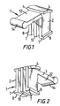
- one form of connector 1 comprises two parts 2 and 3.
- the first part 2 comprises an attachment means including a pair of laterally extending curved shoulder portions 4 and two depending resilient legs 7.
- the free ends of the legs terminate in detents 8 which extend laterally outwards from the connector.
- a third depending member 10 which acts as a stop as will be explained hereafter.
- the second part 3 of the connector 1 comprises a substantially rigid tongue 12 extending longitudinally of the connector 1 and at right angles to the legs 7.
- the free end of this tongue 12 is formed by a cylindrical member 14 of a diameter which is larger than the thickness of the tongue.
- the above described connector 1 is intended to provide a pivotal connection between a windscreen wiper arm having a termination with a forwardly facing keyhole slot (commonly known as a "Terel" termination) and a standard type of windscreen wiper blade having a harness including a main yoke of substantially channel section with an aperture in the base of the channel for attachment purposes.
- a windscreen wiper arm having a termination with a forwardly facing keyhole slot commonly known as a "Terel” termination
- a standard type of windscreen wiper blade having a harness including a main yoke of substantially channel section with an aperture in the base of the channel for attachment purposes.
- Such an arrangment is shown in figures 3 and 4.
- a windscreen wiper arm 20 having an end termination 21 in the form of a plastics moulding.
- This moulding has a socket 23 for receiving the end of the arm 20 and an attachment portion 25 exhibiting a forwardly facing keyhole slot 26 of which the circular section part is shown at 28 while the stem portion is shown at 29.
- the arm 20 is arranged offset from the attachment portion 25.
- the main yoke 40 of a windscreen wiper blade is also shown.
- the main yoke 40 is of channel section with an attachment aperture 42 in the base 43 of the channel.
- the side walls 45 and 46 of the yoke 40 are of increased depth in the region of the aperture 42 and the upper edges of the sides 45 and 46 at the aperture 42 merge into the adjacent parts of the yoke 40 by means of a curved part 48 and an indentation 49.
- Slots 50 are shown in the main yoke 40 to provide improved performance but form no part of the present invention.
- the arm termination 21 is connected to the main yoke 40 by means of a connector 1 as shown in figures 1 and 2.
- the connector 1 is seated in the aperture 42 of the main yoke 40.
- the curved shoulders 4 sit about the curved part 48 of the edge of the aperture 42 and the detents 8 on the ends of the legs 7 protrude under the sidewalls 45 and 46.
- the tongue 12 and cylindrical end part 14 are used for the attachment of the arm termination 21.
- the cylindrical part 14 sits in the enlarged end 28 of the keyhole slot 26 and the tongue 12 sits in the stem portion 29 thereof.
- pivotal movement between arm and blade does not take place about the axis of the slot portion 28 but takes place by virtue of the pivotal play available at the connector which is assisted by the cooperating curved surfaces 4 and 48.
- the connector In order to connect the arm and blade, the connector is first placed on the arm. To do this, the tongue 12 is merely slid sideways into the keyhole slot 26 of the arm termination 21. Then the blade 40 is assembled to the arm 20. To achieve this, the legs 7 are pinched together to reduce the width of the connector 1 and, while the legs 7 are maintained in this position, the connector is inserted into the aperture 42 in the main yoke 40 adjacent to the end thereof. The legs 7 are then released and the connector is pushed home in the aperture. If the connector is located in the correct position, the legs 7 will snap back out again, imprisoning the sides 45 and 46 of the yoke 40 between the shoulders 4 and the detents 8.
- the blade can be detached from the arm by a reverse operation.
- the legs 7 are again pinched together and the connector 1 is pushed up out of the aperture 42 in the main yoke.
- the connector Once the connector is clear of the blade, it can be readily removed from the arm termination 21 by sliding the tongue 12 sideways out of the keyhole slot 26.
- the middle depending member 10 of the connector 1 could be omitted if the stop action is not required.
- the method of attachement of the connector 1 to the blade could be varied.
- the connector 1 could be clipped onto the pin normally provided extending across the aperture 42 in the main yoke 40.
- the curved shoulder 4 could be replaced by a straight shoulder which could be angled relative to the associated detent 8.
Landscapes
- Engineering & Computer Science (AREA)
- Mechanical Engineering (AREA)
- Pivots And Pivotal Connections (AREA)
Claims (3)
Applications Claiming Priority (2)
| Application Number | Priority Date | Filing Date | Title |
|---|---|---|---|
| GB878717834A GB8717834D0 (en) | 1987-07-28 | 1987-07-28 | Connector |
| GB8717834 | 1987-07-28 |
Publications (2)
| Publication Number | Publication Date |
|---|---|
| EP0301822A1 EP0301822A1 (fr) | 1989-02-01 |
| EP0301822B1 true EP0301822B1 (fr) | 1991-03-06 |
Family
ID=10621403
Family Applications (1)
| Application Number | Title | Priority Date | Filing Date |
|---|---|---|---|
| EP88306906A Expired - Lifetime EP0301822B1 (fr) | 1987-07-28 | 1988-07-27 | Joint d'articulation |
Country Status (5)
| Country | Link |
|---|---|
| EP (1) | EP0301822B1 (fr) |
| JP (1) | JPH0194055A (fr) |
| DE (1) | DE3861933D1 (fr) |
| ES (1) | ES2022625B3 (fr) |
| GB (2) | GB8717834D0 (fr) |
Families Citing this family (2)
| Publication number | Priority date | Publication date | Assignee | Title |
|---|---|---|---|---|
| DE10212441A1 (de) | 2002-03-21 | 2003-11-13 | Valeo Auto Electric Gmbh | Wischvorrichtung mit Flachwischblatt und Wischarm |
| DE10362341B3 (de) * | 2002-11-26 | 2023-02-09 | Valeo Wischersysteme Gmbh | Wischerblatt |
Family Cites Families (1)
| Publication number | Priority date | Publication date | Assignee | Title |
|---|---|---|---|---|
| IT7967396A0 (it) * | 1979-02-22 | 1979-02-22 | Arman Spa | Dispositivo di attacco di una spatola tergicristallo al relativobraccio di comando |
-
1987
- 1987-07-28 GB GB878717834A patent/GB8717834D0/en active Pending
-
1988
- 1988-07-27 ES ES88306906T patent/ES2022625B3/es not_active Expired - Lifetime
- 1988-07-27 DE DE8888306906T patent/DE3861933D1/de not_active Expired - Lifetime
- 1988-07-27 EP EP88306906A patent/EP0301822B1/fr not_active Expired - Lifetime
- 1988-07-27 GB GB8817896A patent/GB2207343B/en not_active Expired - Lifetime
- 1988-07-28 JP JP63189520A patent/JPH0194055A/ja active Pending
Also Published As
| Publication number | Publication date |
|---|---|
| DE3861933D1 (de) | 1991-04-11 |
| JPH0194055A (ja) | 1989-04-12 |
| GB2207343B (en) | 1991-09-04 |
| GB8717834D0 (en) | 1987-09-03 |
| EP0301822A1 (fr) | 1989-02-01 |
| ES2022625B3 (es) | 1991-12-01 |
| GB2207343A (en) | 1989-02-01 |
| GB8817896D0 (en) | 1988-09-01 |
Similar Documents
| Publication | Publication Date | Title |
|---|---|---|
| US4308635A (en) | Device for connecting a wiper blade holder to a wiper arm | |
| US4416032A (en) | Connector adaptor for pin-type blade | |
| JP3680028B2 (ja) | ウェーハコネクタ用ラッチング組立体 | |
| US20100186185A1 (en) | Connection base interacting with an adapter for forming therewith mechanical connector for the wiper blade for an automobile | |
| US4296521A (en) | Wiper blades | |
| WO2007117533A1 (fr) | connecteur électrique à mécanisme de verrouillage | |
| EP1215772A3 (fr) | Assemblage de connecteur avec verrouillage | |
| GB2332140A (en) | Wiper blade attachment adapter | |
| CN107226069B (zh) | 连接刮擦器臂自由端的适配器以及包括二者的组件 | |
| EP0236061B1 (fr) | Joint pivotant | |
| EP0231129A2 (fr) | Joint rotatif | |
| EP0168977B1 (fr) | Verrouillage pour connecteur électrique | |
| EP0220883B1 (fr) | Dispositif d'essuyage de pare-brise et de surface semblable et dispositif de connexion utilisé | |
| CA1124462A (fr) | Raccord de lame sur bras d'essuie-glace | |
| EP0301822B1 (fr) | Joint d'articulation | |
| US4429431A (en) | Windshield wiper arm to blade connector | |
| US20050106924A1 (en) | Lockable electrical plug and socket connection | |
| EP0319161A1 (fr) | Connecteur pour balais d'essuyage | |
| US6209166B1 (en) | Windshield wiper | |
| EP0255352B1 (fr) | Joint d'articulation | |
| US3875611A (en) | Pin hole embossment | |
| JPH0195957A (ja) | 回転継手 | |
| EP0300802B1 (fr) | Joint d'articulation | |
| GB2193432A (en) | Connector for connecting wiper blade to wiper arm | |
| EP0692415A1 (fr) | Joint d'articulation |
Legal Events
| Date | Code | Title | Description |
|---|---|---|---|
| PUAI | Public reference made under article 153(3) epc to a published international application that has entered the european phase |
Free format text: ORIGINAL CODE: 0009012 |
|
| AK | Designated contracting states |
Kind code of ref document: A1 Designated state(s): BE DE ES FR IT |
|
| 17P | Request for examination filed |
Effective date: 19890728 |
|
| 17Q | First examination report despatched |
Effective date: 19900424 |
|
| GRAA | (expected) grant |
Free format text: ORIGINAL CODE: 0009210 |
|
| AK | Designated contracting states |
Kind code of ref document: B1 Designated state(s): BE DE ES FR IT |
|
| REF | Corresponds to: |
Ref document number: 3861933 Country of ref document: DE Date of ref document: 19910411 |
|
| ITF | It: translation for a ep patent filed | ||
| ET | Fr: translation filed | ||
| PLBE | No opposition filed within time limit |
Free format text: ORIGINAL CODE: 0009261 |
|
| STAA | Information on the status of an ep patent application or granted ep patent |
Free format text: STATUS: NO OPPOSITION FILED WITHIN TIME LIMIT |
|
| 26N | No opposition filed | ||
| PGFP | Annual fee paid to national office [announced via postgrant information from national office to epo] |
Ref country code: DE Payment date: 20030925 Year of fee payment: 16 |
|
| PG25 | Lapsed in a contracting state [announced via postgrant information from national office to epo] |
Ref country code: DE Free format text: LAPSE BECAUSE OF NON-PAYMENT OF DUE FEES Effective date: 20050201 |
|
| PGFP | Annual fee paid to national office [announced via postgrant information from national office to epo] |
Ref country code: FR Payment date: 20050726 Year of fee payment: 18 |
|
| PG25 | Lapsed in a contracting state [announced via postgrant information from national office to epo] |
Ref country code: IT Free format text: LAPSE BECAUSE OF NON-PAYMENT OF DUE FEES;WARNING: LAPSES OF ITALIAN PATENTS WITH EFFECTIVE DATE BEFORE 2007 MAY HAVE OCCURRED AT ANY TIME BEFORE 2007. THE CORRECT EFFECTIVE DATE MAY BE DIFFERENT FROM THE ONE RECORDED. Effective date: 20050727 |
|
| PGFP | Annual fee paid to national office [announced via postgrant information from national office to epo] |
Ref country code: ES Payment date: 20050830 Year of fee payment: 18 |
|
| PGFP | Annual fee paid to national office [announced via postgrant information from national office to epo] |
Ref country code: BE Payment date: 20050915 Year of fee payment: 18 |
|
| PG25 | Lapsed in a contracting state [announced via postgrant information from national office to epo] |
Ref country code: BE Free format text: LAPSE BECAUSE OF NON-PAYMENT OF DUE FEES Effective date: 20060731 |
|
| REG | Reference to a national code |
Ref country code: FR Ref legal event code: ST Effective date: 20070330 |
|
| REG | Reference to a national code |
Ref country code: ES Ref legal event code: FD2A Effective date: 20060728 |
|
| BERE | Be: lapsed |
Owner name: *TRICO-FOLBERTH LTD Effective date: 20060731 |
|
| PG25 | Lapsed in a contracting state [announced via postgrant information from national office to epo] |
Ref country code: ES Free format text: LAPSE BECAUSE OF NON-PAYMENT OF DUE FEES Effective date: 20060728 |
|
| PG25 | Lapsed in a contracting state [announced via postgrant information from national office to epo] |
Ref country code: FR Free format text: LAPSE BECAUSE OF NON-PAYMENT OF DUE FEES Effective date: 20060731 |