EP0301836B1 - Kontrollkassentisch - Google Patents
Kontrollkassentisch Download PDFInfo
- Publication number
- EP0301836B1 EP0301836B1 EP88306927A EP88306927A EP0301836B1 EP 0301836 B1 EP0301836 B1 EP 0301836B1 EP 88306927 A EP88306927 A EP 88306927A EP 88306927 A EP88306927 A EP 88306927A EP 0301836 B1 EP0301836 B1 EP 0301836B1
- Authority
- EP
- European Patent Office
- Prior art keywords
- basket
- commodity
- check
- receiving surface
- stopper
- Prior art date
- Legal status (The legal status is an assumption and is not a legal conclusion. Google has not performed a legal analysis and makes no representation as to the accuracy of the status listed.)
- Expired - Lifetime
Links
Images


Classifications
-
- A—HUMAN NECESSITIES
- A47—FURNITURE; DOMESTIC ARTICLES OR APPLIANCES; COFFEE MILLS; SPICE MILLS; SUCTION CLEANERS IN GENERAL
- A47F—SPECIAL FURNITURE, FITTINGS, OR ACCESSORIES FOR SHOPS, STOREHOUSES, BARS, RESTAURANTS OR THE LIKE; PAYING COUNTERS
- A47F1/00—Racks for dispensing merchandise; Containers for dispensing merchandise
-
- G—PHYSICS
- G06—COMPUTING OR CALCULATING; COUNTING
- G06K—GRAPHICAL DATA READING; PRESENTATION OF DATA; RECORD CARRIERS; HANDLING RECORD CARRIERS
- G06K7/00—Methods or arrangements for sensing record carriers, e.g. for reading patterns
- G06K7/10—Methods or arrangements for sensing record carriers, e.g. for reading patterns by electromagnetic radiation, e.g. optical sensing; by corpuscular radiation
- G06K7/10544—Methods or arrangements for sensing record carriers, e.g. for reading patterns by electromagnetic radiation, e.g. optical sensing; by corpuscular radiation by scanning of the records by radiation in the optical part of the electromagnetic spectrum
- G06K7/10821—Methods or arrangements for sensing record carriers, e.g. for reading patterns by electromagnetic radiation, e.g. optical sensing; by corpuscular radiation by scanning of the records by radiation in the optical part of the electromagnetic spectrum further details of bar or optical code scanning devices
- G06K7/10861—Methods or arrangements for sensing record carriers, e.g. for reading patterns by electromagnetic radiation, e.g. optical sensing; by corpuscular radiation by scanning of the records by radiation in the optical part of the electromagnetic spectrum further details of bar or optical code scanning devices sensing of data fields affixed to objects or articles, e.g. coded labels
- G06K7/10871—Methods or arrangements for sensing record carriers, e.g. for reading patterns by electromagnetic radiation, e.g. optical sensing; by corpuscular radiation by scanning of the records by radiation in the optical part of the electromagnetic spectrum further details of bar or optical code scanning devices sensing of data fields affixed to objects or articles, e.g. coded labels randomly oriented data-fields, code-marks therefore, e.g. concentric circles-code
-
- A—HUMAN NECESSITIES
- A47—FURNITURE; DOMESTIC ARTICLES OR APPLIANCES; COFFEE MILLS; SPICE MILLS; SUCTION CLEANERS IN GENERAL
- A47F—SPECIAL FURNITURE, FITTINGS, OR ACCESSORIES FOR SHOPS, STOREHOUSES, BARS, RESTAURANTS OR THE LIKE; PAYING COUNTERS
- A47F9/00—Shop, bar, bank or like counters
- A47F9/02—Paying counters
- A47F9/04—Check-out counters, e.g. for self-service stores
-
- A—HUMAN NECESSITIES
- A47—FURNITURE; DOMESTIC ARTICLES OR APPLIANCES; COFFEE MILLS; SPICE MILLS; SUCTION CLEANERS IN GENERAL
- A47F—SPECIAL FURNITURE, FITTINGS, OR ACCESSORIES FOR SHOPS, STOREHOUSES, BARS, RESTAURANTS OR THE LIKE; PAYING COUNTERS
- A47F9/00—Shop, bar, bank or like counters
- A47F9/02—Paying counters
- A47F9/04—Check-out counters, e.g. for self-service stores
- A47F9/046—Arrangement of recording means in or on check-out counters
Definitions
- This invention relates to a check-out counter table of a check-out system which is used in a retail store.
- a cash register and/or a vertical type bar code reader making use of a laser beam are provided in front of a cashier or an operator, and a pair of check-out counter tables each having a flat commodity receiving surface formed thereon are disposed on the left and right sides of the bar code reader.
- a basket in which commodities are contained is placed on the right-hand side commodity receiving surface while an empty basket is placed on the left-hand side commodity receiving surface, and a commodity is taken out from the right-hand side basket while data from the commodity such as data regarding a price is read by the bar code reader, and then the commodity for which registration has been completed is thrown into the left-hand side basket.
- the left-hand side basket is taken away by the customer while the thus emptied right-hand side basket is moved to the left-hand side location by the operator.
- GB Patent Specification 1,185,855 discloses a check-out desk having a horizontally elongated check-out counter body having a rectangular commodity receiving surface, a cash register located at a central region relative to said counter body and a stopper for controlling movement of a commodity basket on said rectangular receiving surface.
- the present invention as defined in independent Claim 1, is characterized in that the stopper is located at a position to stop an incoming basket at an intermediate location on said counter table where commodities can be checked by said bar code reader after which the basket can be moved further along said table and is formed from an elastic member located in a groove within the plane of said receiving surface so as to provide a high contact resistance against sliding of the filled basket beyond the stopper and a lower resistance when the basket is empty.
- FIG. 1 to 4 there is shown a check-out counter table of a first embodiment of the present invention.
- the check-out counter table shown includes a horizontally elongated check-out counter body 1 which has a rectangular commodity receiving wall 2 formed thereon as a flat wall elongated in leftward and rightward directions.
- a vertical type bar code reader 4 is provided substantially at a central location of the check-out counter body 1 with a basket passing portion 3 left in front of the check-out counter body 1.
- the bar code reader 4 has a reading window 5 formed in a front wall thereof through which coded bars printed on a label applied to a commodity are to be read.
- An operation panel 6 is provided in an inclined relationship to the operator side on the bar code reader, and a display section 7 which may be a liquid crystal display device or the like is provided at a portion of the operation panel 6.
- Another display section 8 is provided for a customer on the left side of the operation panel 6.
- a right-hand side portion of the check-out counter body 1 serves as a carrying in side by way of which a basket 9 in which commodities are contained is carried in to the check-out counter body 1, and a guide rail 10 for preventing such a basket 9 from coming off from the check-out counter body 1 extends in the leftward and rightward directions on the front side of the commodity receiving surface 2 of the carrying in side of the check-out counter body 1.
- a stopper 11 is provided at a location of the commodity receiving surface 2 of the check-out counter body 1 directly forwardly of the bar code reader 4.
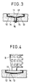
- the stopper 11 is made of an elastic substance such as a rubber material and lies in a substantially same plane with a surface of the commodity receiving surface 2 so that it provides a high contact resistance to the basket 9.
- the check- out counter body 1 has a groove 13 formed in the commodity receiving surface 2 thereof.
- the groove 13 extends in the forward and rearward directions and has a pair of stepped portions 12 such that it may be deeper at a central portion thereof.
- the stopper 11 is held in a stopper holding frame 14 made of stainless steel and mounted in the groove 11.
- a hub 15 is mounted in an integral relationship on the stopper holding frame 14 and is pulled down by means of a machine screw 16 which is mounted in and extends through the commodity receiving surface 2 from the bottom face side of the commodity receiving surface 2 so that the stopper holding frame 14 is secured in position on the stepped portions 12 of the commodity receiving surface 2.
- the stopper holding frame 14 has a depression at a central portion thereof so that a spacing 17 is formed at a central location below the lower face of the stopper 11.
- a basket 9 in which commodities are contained is placed on the right-hand side location of the commodity receiving surface 2 of the check-out counter body 1.
- the basket 9 is placed at a location A shown in Fig. 2.
- An operator thus pulls the basket 9 toward the operator side under the guidance of the guide rail 10, and then when the bottom face of the basket 9 is contacted with the stopper 11, the sliding resistance thereof increases suddenly. Accordingly, the position of the basket 9 is always controlled by the stopper 11 and thus stopped at a fixed location indicated at B in Fig. 2. It is to be noted that, since the location A is vacant then, another basket 9 can be placed at the location A. If the weight of the basket 9 is great, the central portion of the stopper 11 is depressed a little as shown in Fig. 4, thereby promoting the stopping action of the stopper 11.
- an empty basket 9 lies at a location C on the left side of the commodity receiving surface 2, and the operator thus takes out a commodity from the basket 6 on the right side, passes the commodity in front of the reading window 5 of the bar code reader 4, and then throws it into the basket 9 on the left side. Thereupon, coded bars printed on a label applied to the commodity are read out so that various data such as data regarding a price of the commodity is stored in memory.
- the commodity for which data has been read out are all transferred into the basket 9 at the location C in this manner.
- the basket 9 at the location C is then moved by the customer to another location D at which packaging of the commodities or some other operation is conducted. Then, the basket 9 at the location B is moved to the thus vacant location C.
- the weight thereof is so small that it can be slipped on the commodity receiving surface 2 of the check-out counter body 1 by a relatively small force although the contacting resistance by the stopper 11 is high. Further, even if the stopper 11 has been deformed in such a manner as shown in Fig. 4, the degree of deformation thereof is reduced so that the stopper 11 will not make an obstruction to movement of the basket 9 to the location C.
- stopper 11 is described formed from an elastic substance, it may otherwise be formed from a material in the form of a sheet only if it presents a high contacting resistance.
- FIG. 5 and 6 there is shown a check-out counter table according to a second embodiment of the present invention.
- the check-out counter table shown has a vertical stationary type bar code reader 20 provided thereon.
- the bar code reader 20 has a reading window 21 formed in a front wall thereof and has an operation panel 22 and a display section 23 disposed at an upper wall thereof.
- the bar code reader 20 is secured to a central portion of a horizontally elongated commodity counter 24.
- the check-out counter table here is designed such that bar code data of a commodity 25 may be read by the bar code reader 20 during movement of the commodity 25 when the commodity 25 picked up from a basket 26 which is placed on one side of the commodity counter 24 and in which commodities 25 are contained is passed in front of the reading window 21 of the bar code reader 20 and put into another empty basket 26 which is placed on the other side of the commodity receiving table 24.
- the commodity counter 24 includes a flat high located commodity receiving surface 27 formed on the right-hand side thereof at a relatively high location, a central commodity receiving surface 28 contiguous to the high located commodity receiving surface 27 and inclined downwardly toward the left side, and a flat low located commodity receiving surface 29 contiguous to the central commodity receiving surface 28 and formed at the left-hand side location thereof.
- a pair of stoppers 30 are provided at a left end portion of the high located commodity receiving surface 27 and at a left end portion of the low located commodity receiving surface 29.
- the stoppers 30 are disposed substantially in the same planes with surfaces of the commodity receiving surface 27 and 29 and adapted to present a high contacting resistance.
- Each of the stoppers 30 has a similar structure to that of the stopper 11 in the preceding embodiment described hereinabove with reference to Fig. 3.
- a basket 26 in which commodities 25 are contained is placed on the high located commodity receiving surface 27 of the commodity counter 24.
- the customer waiting for check-out stands at a location away from the high located commodity receiving surface 27 of the commodity counter 24, and when the turn for check-out comes to the customer, the basket 26 is slidably moved to a location on the high located commodity receiving surface 27 near the central commodity receiving surface 28.
- an end of a lower portion of the basket 26 rides on the stopper 30 which presents a high contacting friction so that the sliding resistance increases suddenly.
- the basket 26 will be stopped once even if it is slidably moved inadvertently, and hence such an accident can be prevented that the basket 26 may fall down toward the downwardly inclined central commodity receiving surface 28 so that the commodities 25 therein are scattered.
- the stopper 30 is deformed downwardly in response to an amount of the commodities 25 within the basket 26, that is, in response to the total weight of the commodities 25. Then, if a commodity 25 is taken out from the basket 26 on the high located commodity receiving surface 27 of the commodity counter 24, moved linearly while being inclined downwardly and then put into the basket 26 on the low located commodity receiving surface 29, bar code data of the commodity 25 is read out by the bar code reader 20 when it passes in front of the reading window 21.
- the basket 26 in which the commodities 25 for which data has been read are contained is moved toward the outer end side of the low located commodity receiving surface 29 of the commodity counter 24 and then taken away from the commodity counter 24. Also in this instance, the basket 26 may be slipped on the low located commodity receiving surface 29. But, since the stopper 30 thereupon stops the basket 26 once at a predetermined location as described hereinabove, the basket 26 will not drop from the commodity counter 24.
- the emptied basket 26 remaining on the high located commodity receiving surface 27 of the commodity counter 24 is now light in weight and is reduced in frictional resistance with respect to the stopper 30, it can be readily slipped over the stopper 30 when it is to be subsequently moved toward the low located commodity receiving surface 29.
- the central commodity receiving surface 28 of the commodity applying table 24 may otherwise be set at the same level with the low located commodity receiving surface 29 with its right end connected to the high located commodity receiving surface 27 by means of a vertical wall.
- the bar code reader 20 may otherwise be formed in an integral relationship with the commodity counter 24 or else be formed independently of and mounted on the central commodity receiving surface 28 or else may be provided independently of the commodity counter 24.
Landscapes
- Physics & Mathematics (AREA)
- Electromagnetism (AREA)
- Engineering & Computer Science (AREA)
- Health & Medical Sciences (AREA)
- General Health & Medical Sciences (AREA)
- Toxicology (AREA)
- Artificial Intelligence (AREA)
- Computer Vision & Pattern Recognition (AREA)
- General Physics & Mathematics (AREA)
- Theoretical Computer Science (AREA)
- Cash Registers Or Receiving Machines (AREA)
- Warehouses Or Storage Devices (AREA)
Claims (3)
dadurch gekennzeichnet,
daß der Stillsetzer (11) bei einer Position zum Anhalten eines ankommenden Korbes bei einer Mittellager auf dem Kassentisch direkt vor dem Streifencodeleser angeordnet ist, von wo Waren durch den Streifencodeleser geprüft werden können, wonach der Korb entlang dem Kassentisch weiterbewegt werden kann, und aus einem elastischen Teil gebildet wird, das innerhalb einer Nute (13) in der Ebene der Aufnahmefläche (2) angeordnet ist, um so einen hohen Kontaktwiderstand gegen das Gleiten des gefüllten Korbes über den Stillsetzer hinaus zu bilden und einen niedrigeren Widerstand zu bilden, wenn der Korb leer ist.
Applications Claiming Priority (4)
| Application Number | Priority Date | Filing Date | Title |
|---|---|---|---|
| JP11518187U JPH0517749Y2 (de) | 1987-07-28 | 1987-07-28 | |
| JP115181/87U | 1987-07-28 | ||
| JP1987144897U JPH0521163Y2 (de) | 1987-09-22 | 1987-09-22 | |
| JP144897/87U | 1987-09-22 |
Publications (2)
| Publication Number | Publication Date |
|---|---|
| EP0301836A1 EP0301836A1 (de) | 1989-02-01 |
| EP0301836B1 true EP0301836B1 (de) | 1992-02-19 |
Family
ID=26453746
Family Applications (1)
| Application Number | Title | Priority Date | Filing Date |
|---|---|---|---|
| EP88306927A Expired - Lifetime EP0301836B1 (de) | 1987-07-28 | 1988-07-27 | Kontrollkassentisch |
Country Status (5)
| Country | Link |
|---|---|
| US (1) | US4938317A (de) |
| EP (1) | EP0301836B1 (de) |
| KR (1) | KR920004615B1 (de) |
| CA (1) | CA1301903C (de) |
| DE (1) | DE3868452D1 (de) |
Families Citing this family (5)
| Publication number | Priority date | Publication date | Assignee | Title |
|---|---|---|---|---|
| US5195613A (en) * | 1988-09-20 | 1993-03-23 | Tokyo Electric Co., Ltd. | Commodity data reader |
| JP2732497B2 (ja) * | 1988-09-21 | 1998-03-30 | 株式会社テック | 商品データ読取装置 |
| US5252814A (en) * | 1992-08-17 | 1993-10-12 | Ncr Corporation | Multi-scanner checkout counter using digitizer panel to determine X-Y location of scanned items |
| USD368398S (en) | 1994-07-15 | 1996-04-02 | At&T Global Information Solutions Company | Gap filler between checkout counter and bar code scanner |
| US20020112940A1 (en) * | 2001-02-16 | 2002-08-22 | Scott Dickover | Methods and apparatus for improved self-checkout system |
Family Cites Families (17)
| Publication number | Priority date | Publication date | Assignee | Title |
|---|---|---|---|---|
| US1510435A (en) * | 1921-07-23 | 1924-09-30 | Jenny Wren Stores Inc | Apparatus for vending merchandise |
| US1714745A (en) * | 1927-01-08 | 1929-05-28 | Adolph C Woerfel | Store arrangement and fixture |
| NL250675A (de) * | 1959-04-21 | |||
| FR1417485A (fr) * | 1963-12-04 | 1965-11-12 | Indive Gmbh | Meuble de caisse notamment pour magasins à libre service |
| GB1185855A (en) * | 1967-08-09 | 1970-03-25 | Cater Brothers Provisions Ltd | An improved Check-Out Desk |
| US4239099A (en) * | 1979-04-04 | 1980-12-16 | The Mead Corporation | Automatic forward-feed shelf |
| US4369361A (en) * | 1980-03-25 | 1983-01-18 | Symbol Technologies, Inc. | Portable, stand-alone, desk-top laser scanning workstation for intelligent data acquisition terminal and method of scanning |
| US4422745A (en) * | 1981-07-31 | 1983-12-27 | National School Studios, Inc. | Camera system |
| JPS5866925U (ja) * | 1981-10-30 | 1983-05-07 | 住友重機械工業株式会社 | 金型への接続装置 |
| US4792018A (en) * | 1984-07-09 | 1988-12-20 | Checkrobot Inc. | System for security processing of retailed articles |
| FR2573297A1 (fr) * | 1984-11-19 | 1986-05-23 | Rasec | Dispositif d'entree pour meuble d'encaissement de magasin libre-service |
| US4652732A (en) * | 1985-09-17 | 1987-03-24 | National Semiconductor Corporation | Low-profile bar code scanner |
| JPS62154531A (ja) * | 1985-12-27 | 1987-07-09 | Ricoh Co Ltd | 螢光表示管における螢光面形成方法 |
| JPH0769983B2 (ja) * | 1987-03-16 | 1995-07-31 | 株式会社テック | 商品情報読取装置 |
| US4762984A (en) * | 1987-09-11 | 1988-08-09 | Metrologic Instruments, Inc. | Laser scanner apparatus with adjustable mount for connectors |
| US4789048A (en) * | 1987-09-28 | 1988-12-06 | Ncr Corporation | Checkout counter |
| US4853521A (en) * | 1987-12-28 | 1989-08-01 | Claeys Ronald W | System for verifying and recording drug administration to a patient |
-
1988
- 1988-07-19 CA CA000572464A patent/CA1301903C/en not_active Expired - Lifetime
- 1988-07-22 US US07/223,029 patent/US4938317A/en not_active Expired - Fee Related
- 1988-07-27 DE DE8888306927T patent/DE3868452D1/de not_active Expired - Lifetime
- 1988-07-27 KR KR1019880009477A patent/KR920004615B1/ko not_active Expired
- 1988-07-27 EP EP88306927A patent/EP0301836B1/de not_active Expired - Lifetime
Also Published As
| Publication number | Publication date |
|---|---|
| US4938317A (en) | 1990-07-03 |
| KR920004615B1 (ko) | 1992-06-12 |
| KR890001494A (ko) | 1989-03-27 |
| CA1301903C (en) | 1992-05-26 |
| DE3868452D1 (de) | 1992-03-26 |
| EP0301836A1 (de) | 1989-02-01 |
Similar Documents
| Publication | Publication Date | Title |
|---|---|---|
| US4838383A (en) | Apparatus for checking out purchases | |
| US4789048A (en) | Checkout counter | |
| EP2668878B1 (de) | Abrechnungsanlage | |
| US4138000A (en) | Checkout counter | |
| KR930000678B1 (ko) | 상품데이터 판독장치 | |
| EP0490603A1 (de) | Optischer Abtastapparat zum Lesen von verschlüsselten Symbolen | |
| JPH011099A (ja) | 商品情報読取装置 | |
| EP0508708A1 (de) | Anordnung zum Bearbeiten und Identifizieren von Gegenständen | |
| EP0301836B1 (de) | Kontrollkassentisch | |
| KR920006326B1 (ko) | 상품판매 데이터 처리장치 | |
| US5120941A (en) | Self-service sales system for large containers using bar coded peel-off labels | |
| US5040636A (en) | Merchandise checkout work station | |
| JPH0517749Y2 (de) | ||
| JP2549502B2 (ja) | 商品情報読取装置 | |
| DE19755331A1 (de) | Rücknahmesystem für Abpackungen des Handels | |
| JP2549501B2 (ja) | 商品情報読取装置 | |
| JPH0248949Y2 (de) | ||
| WO1992013769A1 (en) | Arrangement for price labelling of articles | |
| JPS6126998Y2 (de) | ||
| NL1001030C2 (nl) | Uitgangscontrole-inrichting voor zelfbedieningswinkel. | |
| DE2065630A1 (de) | Kassenstand mit eingebauter warentransporteinrichtung | |
| JP2706148B2 (ja) | 商品データ読取装置 | |
| JPH0521163Y2 (de) | ||
| JPH06237845A (ja) | チェックアウト装置 | |
| JPH0342508Y2 (de) |
Legal Events
| Date | Code | Title | Description |
|---|---|---|---|
| PUAI | Public reference made under article 153(3) epc to a published international application that has entered the european phase |
Free format text: ORIGINAL CODE: 0009012 |
|
| 17P | Request for examination filed |
Effective date: 19880906 |
|
| AK | Designated contracting states |
Kind code of ref document: A1 Designated state(s): DE FR GB |
|
| 17Q | First examination report despatched |
Effective date: 19900612 |
|
| GRAA | (expected) grant |
Free format text: ORIGINAL CODE: 0009210 |
|
| AK | Designated contracting states |
Kind code of ref document: B1 Designated state(s): DE FR GB |
|
| REF | Corresponds to: |
Ref document number: 3868452 Country of ref document: DE Date of ref document: 19920326 |
|
| ET | Fr: translation filed | ||
| PGFP | Annual fee paid to national office [announced via postgrant information from national office to epo] |
Ref country code: FR Payment date: 19920428 Year of fee payment: 5 |
|
| PLBE | No opposition filed within time limit |
Free format text: ORIGINAL CODE: 0009261 |
|
| STAA | Information on the status of an ep patent application or granted ep patent |
Free format text: STATUS: NO OPPOSITION FILED WITHIN TIME LIMIT |
|
| 26N | No opposition filed | ||
| PGFP | Annual fee paid to national office [announced via postgrant information from national office to epo] |
Ref country code: GB Payment date: 19930715 Year of fee payment: 6 |
|
| PGFP | Annual fee paid to national office [announced via postgrant information from national office to epo] |
Ref country code: DE Payment date: 19930830 Year of fee payment: 6 |
|
| PG25 | Lapsed in a contracting state [announced via postgrant information from national office to epo] |
Ref country code: FR Effective date: 19940331 |
|
| REG | Reference to a national code |
Ref country code: FR Ref legal event code: ST |
|
| PG25 | Lapsed in a contracting state [announced via postgrant information from national office to epo] |
Ref country code: GB Effective date: 19940727 |
|
| GBPC | Gb: european patent ceased through non-payment of renewal fee |
Effective date: 19940727 |
|
| PG25 | Lapsed in a contracting state [announced via postgrant information from national office to epo] |
Ref country code: DE Effective date: 19950401 |