EP0301840A2 - Recuisson d'une fibre optique bombée - Google Patents
Recuisson d'une fibre optique bombée Download PDFInfo
- Publication number
- EP0301840A2 EP0301840A2 EP88306933A EP88306933A EP0301840A2 EP 0301840 A2 EP0301840 A2 EP 0301840A2 EP 88306933 A EP88306933 A EP 88306933A EP 88306933 A EP88306933 A EP 88306933A EP 0301840 A2 EP0301840 A2 EP 0301840A2
- Authority
- EP
- European Patent Office
- Prior art keywords
- fiber
- bent
- optical fiber
- intermediate section
- strain
- Prior art date
- Legal status (The legal status is an assumption and is not a legal conclusion. Google has not performed a legal analysis and makes no representation as to the accuracy of the status listed.)
- Withdrawn
Links
Images

Classifications
-
- G—PHYSICS
- G02—OPTICS
- G02B—OPTICAL ELEMENTS, SYSTEMS OR APPARATUS
- G02B6/00—Light guides; Structural details of arrangements comprising light guides and other optical elements, e.g. couplings
- G02B6/24—Coupling light guides
- G02B6/255—Splicing of light guides, e.g. by fusion or bonding
- G02B6/2552—Splicing of light guides, e.g. by fusion or bonding reshaping or reforming of light guides for coupling using thermal heating, e.g. tapering, forming of a lens on light guide ends
Definitions
- the present invention relates to forming bent optical fibers, and optical fiber bends and elbows created thereby, so as to reduce static strain thereat, and hence is an improvement over the invention disclosed in copending serial no. 899,363 filed 22 August 1986, assigned to the assignee of the invention, the disclosure of which is incorporated herein by reference.
- Optical fiber has recently been recognized as providing significant advantages over electrical conductors for information transfer. Accordingly, optical fiber has been extensively deployed through a variety of environments where information transfer is desired. In deploying optical fiber, it is often necessary that the fiber be bent, and a minimum bend radius about which the optical fiber can be bent is typically limited by static fatigue which causes the fiber to fracture in time.
- R min is 1.87 cm, 2.1 cm and 3.75 cm. respectively, when ⁇ equals 1.0% which corresponds to a 100 kpsi proof test stress.
- Such values for the minimum bend radius are often too large for practical applications, and consequently limit the use of optical fiber for high density interconnect systems and other applications where space is a premium and hence small fiber bend radii are required.
- forming a bent optical fiber by: stressing an intermediate section of the optical fiber so as to create a bend in the fiber; and heating the bent intermediate section of an optical fiber at a temperature sufficient large and for an amount of time sufficiently long to remove at least some stress in the bend in the intermediate section of the optical fiber.
- a minimum bend radius for an optical fiber is reduced by annealing a bent section of an optical fiber so as to minimize or eliminate any strain in the optical fiber at its bend section, which strain otherwise would cause the fiber to fracture in a relatively short period of time due to static fatigue.
- the optical fiber is annealed by maintaining the fiber at an elevated temperature while creating a bent section therein by use of an external stress, and maintaining the temperature and stress until substantially all the strain in the fiber bent section has been annealed out of the bent section, and then cooling the fiber bent section and removing the external stress.
- the fiber temperature is kept high enough to anneal the fiber within a reasonable time, but is kept low enough to prevent any detrimental deformation of the fiber or significant dopant defusion in the fiber.
- the fabrication process takes place in an inert, dry environment, e.g. a nitrogen atmosphere, to prevent any degradation of fiber strength.
- the invention is suitable for fabricating bends in any type of fiber, preferred embodiments including single mode and multimode fiber, both step and graded index, and is suitable for plastic clad glass core fiber as well as glass-on-glass fiber, e.g. fiber which includes a glass core surrounded by a glass cladding, preferred embodiments including fiber having a cylindrical core and a cylindrical cladding, preferably the glass comprising silica.
- a protective coating e.g. buffer and/or jacket, over the cladding is preferably removed prior to heating, and upon completion of the heat/bend/annealing treatment preferably a new coating is applied to the annealed bend.
- the coating which is removed from the fiber constitutes an acrylate or silicone fiber buffer.
- the new protective coating is preferably chosen so as to have an index of refraction which is less than that of the fiber cladding so as to minimize light loss at the bend, especially when a small bend radius is to be formed, such light loss being characteristic at small bend radii if an index matching coating is used.
- the new protective coating has an index of refraction higher than the cladding.
- silicone having an index of refraction of 1.41 is suitable, and when the new coating is to have a high index of refraction, polyacrylate having an index of refraction of 1.48 is suitable, for example.
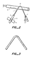
- Figure 1 illustrates one preferred method for carrying out one preferred embodiment of the invention.
- an optical fiber 1 having a polymeric coating, e.g. buffer 2 thereon has had a section of the buffer 2 removed from a section 3 of the optical fiber.
- the fiber section 3 is disposed over a cylindrically-shaped cartridge heater 4 having a radius of curvature which roughly corresponds to that desired to be formed on the optical fiber section 3.
- the buffer end 5 is fixedly retained by a fixture 6, while an opposite section 7 of the optical fiber has a small weight 9 attached thereto.
- the force of the weight 9 causes a section 10 of the optical fiber in contact with the cartridge heater 4 to bend, as illustrated in Figure 2.
- the fiber is cooled, and substantially maintains its bent attitude, as illustrated in Figure 3, with minimum internal strain at the bend.
- the fiber can be heated in an oven with no contact being made to its bent section, or the fiber could be heated with a radiant heater.
- the invention as described can be used to permanently bend a much tighter radius in an optical fiber without a significant fear of static fatigue failure.
- the technique for forming such fiber is useful in any application where space is limited, such uses being in transmitter/receiver units for optical communications, and also for various fiber optic sensors such as fiber gyroscopes. More importantly, the invention eliminates any strain in bent fiber which is responsible for static fatigue corrosion, and improves reliability of routed optical fiber drastically.
- a continuous length of optical fiber can be treated as described to create a bend in an intermediate section thereof, thus creating an elbow joint equivalent therein without the need for splicing.
- Such bends could be useful in routing fiber where tight corners need to be negotiated, or alternatively can be created at locations where a passive tap is to be disposed at a bend such as in ring or bus architectures, and preferably in any of the architectures described in pending U.S. application serial no. 754,035, filed July 11, 1985, assigned to the assignee of the invention, the disclosure of which is incorporated herein by reference.
- preferred embodiments include the formation of discreet elbow fiber connections which can be used to connect discreet sections of optical fiber lines around tight corners of wherever necessary, such elbow connections being deliverable to craftsmen in the field or personnel in assembly plants for connection, as desired.
- the annealing temperature is lower than a melting point of the material forming the fiber, for silicon the melting temperature being about 2000°C.
- a temperature below 2000°C is preferred, more preferably below 1600°C, more preferably below 1400°C, but yet the temperature should be maintained high enough to allow substantial annealing to take place in a reasonable amount of time, e.g. within seconds or minutes, a preferred temperature being above 500°C, more preferably above 700°C, e.g. 500°C to 2000°C or 600°C to 1400°C, the invention including all combinations of the ranges of temperatures set forth above.
- a bend of radius 4 mm creates a strain therein of 1.56%.
- the strain for such an untreated fiber is about 2.08%.
- the strain in the untreated fiber was 3.94%.
- the invention is usable for forming permanent elbow sections of fiber bent sections having a radius of curvature sufficiently small such that a strain which would otherwise exist in an untreated fiber would exceed 0.1%, alternatively would exceed 0.5%, alternatively would exceed 1.0%, and would even exceed 2.0%, 3.0%, 5.0% and even 8.0%. As indicated, it is highly desirable that the fiber be at its elevated temperature prior to beginning the bending operation.
Landscapes
- Physics & Mathematics (AREA)
- Engineering & Computer Science (AREA)
- Plasma & Fusion (AREA)
- General Physics & Mathematics (AREA)
- Optics & Photonics (AREA)
- Optical Fibers, Optical Fiber Cores, And Optical Fiber Bundles (AREA)
- Re-Forming, After-Treatment, Cutting And Transporting Of Glass Products (AREA)
Applications Claiming Priority (2)
| Application Number | Priority Date | Filing Date | Title |
|---|---|---|---|
| US78356 | 1987-07-28 | ||
| US07/078,356 US4812001A (en) | 1987-07-28 | 1987-07-28 | Annealing bent optical fiber |
Publications (2)
| Publication Number | Publication Date |
|---|---|
| EP0301840A2 true EP0301840A2 (fr) | 1989-02-01 |
| EP0301840A3 EP0301840A3 (fr) | 1990-05-23 |
Family
ID=22143516
Family Applications (1)
| Application Number | Title | Priority Date | Filing Date |
|---|---|---|---|
| EP88306933A Withdrawn EP0301840A3 (fr) | 1987-07-28 | 1988-07-27 | Recuisson d'une fibre optique bombée |
Country Status (3)
| Country | Link |
|---|---|
| US (1) | US4812001A (fr) |
| EP (1) | EP0301840A3 (fr) |
| JP (1) | JPS6449002A (fr) |
Cited By (10)
| Publication number | Priority date | Publication date | Assignee | Title |
|---|---|---|---|---|
| EP0441606A3 (en) * | 1990-02-07 | 1992-01-08 | Coherent, Inc. | Contact laser delivery system |
| EP0533847A4 (en) * | 1990-06-15 | 1993-07-07 | Aster Corporation | Miniature fiberoptic bend device and method |
| WO1996035931A1 (fr) * | 1995-05-11 | 1996-11-14 | Poole Craig D | Dispositif optique de mesure de puissance utilisant un circuit a faible courant |
| EP0889336A3 (fr) * | 1997-06-30 | 1999-12-15 | Hoya Corporation | Procédé de reduction des déformations de fibres optiques |
| EP1076251A1 (fr) * | 1999-08-11 | 2001-02-14 | Thomas & Betts International, Inc. | Epissure au niveau d'une mini-courbure dans une fibre optique et procédé de formation de celle-ci |
| EP0984310A3 (fr) * | 1998-08-25 | 2001-09-12 | Thomas & Betts International, Inc. | Séparateur à fibre optique monoface ayant une mini-courbure intégrée |
| US6976792B1 (en) | 2000-09-26 | 2005-12-20 | International Business Machines Corporation | Optical fiber space transformation |
| US7269320B2 (en) | 2004-11-13 | 2007-09-11 | Afl Telecommunications, Llc | Fiber optic cable with miniature bend incorporated |
| CN105765427A (zh) * | 2013-11-25 | 2016-07-13 | 住友电气工业株式会社 | 弯曲光纤的制造方法 |
| CN105829936A (zh) * | 2013-12-18 | 2016-08-03 | 住友电气工业株式会社 | 光学互连部件 |
Families Citing this family (15)
| Publication number | Priority date | Publication date | Assignee | Title |
|---|---|---|---|---|
| US5408554A (en) * | 1993-12-17 | 1995-04-18 | Porta System Corporation | Fiber optic coupling |
| US6059224A (en) * | 1998-06-22 | 2000-05-09 | Siecor Operations, Llc | Method and apparatus for guiding fibers or ribbons under tension |
| JP2005292718A (ja) * | 2004-04-05 | 2005-10-20 | Furukawa Electric Co Ltd:The | 光導波路、光導波路モジュールおよび光導波路の作成方法 |
| SE0401632D0 (sv) * | 2004-06-24 | 2004-06-24 | Innovation Team Ab | Medel och sätt att detektera blodläckage från sår |
| JP5224317B2 (ja) * | 2006-11-20 | 2013-07-03 | 古河電気工業株式会社 | 光導波路部品および光導波路部品の製造方法 |
| US8795522B2 (en) * | 2007-03-15 | 2014-08-05 | Fram Group Ip Llc | Lubricating oil conditioning filter containing improved pelletized conditioner |
| US7817884B2 (en) * | 2007-10-30 | 2010-10-19 | Corning Incorporated | Strain-managed optical waveguide assemblies and methods of forming same |
| JP5224337B2 (ja) * | 2008-03-31 | 2013-07-03 | 古河電気工業株式会社 | 光導波路コネクタ及び光導波路コネクタの製造方法 |
| JP5253946B2 (ja) * | 2008-09-16 | 2013-07-31 | 株式会社巴川製紙所 | 光伝送媒体成形方法および光伝送媒体成形装置 |
| WO2013042337A1 (fr) * | 2011-09-20 | 2013-03-28 | パナソニック株式会社 | Fibre optique, laser à fibre qui utilise cette dernière et procédé de fabrication d'une fibre optique |
| KR101529456B1 (ko) * | 2012-06-21 | 2015-06-16 | 에이비비 테크놀로지 리미티드 | 복합 케이블의 제 1 광섬유와 제 2 광섬유를 조인팅하기 위한 장치 및 방법 |
| WO2014087974A1 (fr) * | 2012-12-05 | 2014-06-12 | 住友電気工業株式会社 | Guide d'ondes optiques, et système de transmission à fibres optiques |
| US20150160075A1 (en) * | 2013-10-18 | 2015-06-11 | Weatherford/Lamb, Inc. | Cane-based u-bend |
| JP6417710B2 (ja) * | 2014-05-20 | 2018-11-07 | 住友電気工業株式会社 | 屈曲光ファイバ製造方法 |
| EP3168663A4 (fr) | 2014-07-11 | 2018-02-21 | Furukawa Electric Co., Ltd. | Connecteur à fibres optiques intégrées pouvant se cintrer et procédé de production de fibres optiques pouvant se cintrer |
Family Cites Families (3)
| Publication number | Priority date | Publication date | Assignee | Title |
|---|---|---|---|---|
| US3775530A (en) * | 1971-08-13 | 1973-11-27 | Dow Chemical Co | Manufacture of composites containing a thermally shaped inorganic fiber form |
| EP0257999B1 (fr) * | 1986-08-22 | 1993-04-28 | RAYCHEM CORPORATION (a California corporation) | Système de communication à fibres optiques sous tension et distribuées |
| JPH06126012A (ja) * | 1992-10-14 | 1994-05-10 | Atena Burein Kk | ゴルフシミュレータ |
-
1987
- 1987-07-28 US US07/078,356 patent/US4812001A/en not_active Expired - Fee Related
-
1988
- 1988-07-27 EP EP88306933A patent/EP0301840A3/fr not_active Withdrawn
- 1988-07-28 JP JP63191982A patent/JPS6449002A/ja active Pending
Cited By (13)
| Publication number | Priority date | Publication date | Assignee | Title |
|---|---|---|---|---|
| EP0441606A3 (en) * | 1990-02-07 | 1992-01-08 | Coherent, Inc. | Contact laser delivery system |
| EP0533847A4 (en) * | 1990-06-15 | 1993-07-07 | Aster Corporation | Miniature fiberoptic bend device and method |
| US5452393A (en) * | 1990-06-15 | 1995-09-19 | Aster Corporation | Miniature fiberoptic bend device and method |
| WO1996035931A1 (fr) * | 1995-05-11 | 1996-11-14 | Poole Craig D | Dispositif optique de mesure de puissance utilisant un circuit a faible courant |
| EP0889336A3 (fr) * | 1997-06-30 | 1999-12-15 | Hoya Corporation | Procédé de reduction des déformations de fibres optiques |
| EP0984310A3 (fr) * | 1998-08-25 | 2001-09-12 | Thomas & Betts International, Inc. | Séparateur à fibre optique monoface ayant une mini-courbure intégrée |
| EP0989427A3 (fr) * | 1998-08-25 | 2001-12-19 | Thomas & Betts International, Inc. | Micro-courbures assymétriques dans des fibres optiques et leur méthode de fabrication |
| EP1076251A1 (fr) * | 1999-08-11 | 2001-02-14 | Thomas & Betts International, Inc. | Epissure au niveau d'une mini-courbure dans une fibre optique et procédé de formation de celle-ci |
| US6612753B1 (en) | 1999-08-11 | 2003-09-02 | Alcoa Fujikura Ltd. | Miniature bend splice in optical fibers and method of forming same |
| US6976792B1 (en) | 2000-09-26 | 2005-12-20 | International Business Machines Corporation | Optical fiber space transformation |
| US7269320B2 (en) | 2004-11-13 | 2007-09-11 | Afl Telecommunications, Llc | Fiber optic cable with miniature bend incorporated |
| CN105765427A (zh) * | 2013-11-25 | 2016-07-13 | 住友电气工业株式会社 | 弯曲光纤的制造方法 |
| CN105829936A (zh) * | 2013-12-18 | 2016-08-03 | 住友电气工业株式会社 | 光学互连部件 |
Also Published As
| Publication number | Publication date |
|---|---|
| US4812001A (en) | 1989-03-14 |
| EP0301840A3 (fr) | 1990-05-23 |
| JPS6449002A (en) | 1989-02-23 |
Similar Documents
| Publication | Publication Date | Title |
|---|---|---|
| US4812001A (en) | Annealing bent optical fiber | |
| US9335224B2 (en) | High temperature fiber optic turnaround | |
| EP0607345B1 (fr) | Cordon spirale en fibre optique a flexibilite elevee | |
| US5658364A (en) | Method of making fiber optic-to-metal connection seals | |
| US6269207B1 (en) | Methods and apparatusses for packaging long-period fiber gratings | |
| GB1595638A (en) | Optical waveguides with protective coating | |
| US5295213A (en) | Optical connector with ion exchange hardening | |
| EP0076575B1 (fr) | Fibre optique insensible aux variations de température | |
| US5337387A (en) | Method for the continuous processing of hermetic fiber optic components and the resultant fiber optic-to-metal components | |
| EP0519440A2 (fr) | Procédé de fabrication d'un coupleur à fibre optique | |
| JPH07115878B2 (ja) | 大きな引張り力で延伸することによって機械抵抗の大きい光ファイバを製造する方法 | |
| EP0274222B1 (fr) | Traversée pour fibre optique | |
| US6436198B1 (en) | Method and apparatus for removing polymeric coatings from optical fiber | |
| US7003985B2 (en) | Method and apparatus for removing polymeric coatings from optical fiber in a non-oxidizing environment | |
| US20020012504A1 (en) | Angled fiber optic connector | |
| US5263104A (en) | Optical fiber directional coupler housing | |
| JPH0357447B2 (fr) | ||
| EP0312594B1 (fr) | Fibre optique amelioree de preservation de la polarisation et son procede de fabrication | |
| JP2925173B2 (ja) | ファイバスコープ | |
| CA1191029A (fr) | Reduction de la perte de resistance des fibres en cours de traitement | |
| JPWO2020080385A1 (ja) | 光ファイバケーブル | |
| JP3406034B2 (ja) | カーボンコート光ファイバ | |
| Yoshiyagawa et al. | Optical transmission properties of low loss-large numerical aperture glass fibers made by the double-crucible technique | |
| JPH0360093B2 (fr) | ||
| Gebizlioglu et al. | Materials issues in the development and use of lightguide fibers, cables, and components |
Legal Events
| Date | Code | Title | Description |
|---|---|---|---|
| PUAI | Public reference made under article 153(3) epc to a published international application that has entered the european phase |
Free format text: ORIGINAL CODE: 0009012 |
|
| 17P | Request for examination filed |
Effective date: 19880802 |
|
| AK | Designated contracting states |
Kind code of ref document: A2 Designated state(s): AT BE CH DE ES FR GB IT LI NL SE |
|
| PUAL | Search report despatched |
Free format text: ORIGINAL CODE: 0009013 |
|
| AK | Designated contracting states |
Kind code of ref document: A3 Designated state(s): AT BE CH DE ES FR GB IT LI NL SE |
|
| 17Q | First examination report despatched |
Effective date: 19910315 |
|
| STAA | Information on the status of an ep patent application or granted ep patent |
Free format text: STATUS: THE APPLICATION IS DEEMED TO BE WITHDRAWN |
|
| 18D | Application deemed to be withdrawn |
Effective date: 19910726 |