EP0301870A2 - Dispositif d'affichage - Google Patents
Dispositif d'affichage Download PDFInfo
- Publication number
- EP0301870A2 EP0301870A2 EP88306978A EP88306978A EP0301870A2 EP 0301870 A2 EP0301870 A2 EP 0301870A2 EP 88306978 A EP88306978 A EP 88306978A EP 88306978 A EP88306978 A EP 88306978A EP 0301870 A2 EP0301870 A2 EP 0301870A2
- Authority
- EP
- European Patent Office
- Prior art keywords
- rotatable member
- display device
- light
- rotation
- rotatable
- Prior art date
- Legal status (The legal status is an assumption and is not a legal conclusion. Google has not performed a legal analysis and makes no representation as to the accuracy of the status listed.)
- Withdrawn
Links
Images




Classifications
-
- F—MECHANICAL ENGINEERING; LIGHTING; HEATING; WEAPONS; BLASTING
- F21—LIGHTING
- F21S—NON-PORTABLE LIGHTING DEVICES; SYSTEMS THEREOF; VEHICLE LIGHTING DEVICES SPECIALLY ADAPTED FOR VEHICLE EXTERIORS
- F21S10/00—Lighting devices or systems producing a varying lighting effect
- F21S10/06—Lighting devices or systems producing a varying lighting effect flashing, e.g. with rotating reflector or light source
-
- G—PHYSICS
- G09—EDUCATION; CRYPTOGRAPHY; DISPLAY; ADVERTISING; SEALS
- G09G—ARRANGEMENTS OR CIRCUITS FOR CONTROL OF INDICATING DEVICES USING STATIC MEANS TO PRESENT VARIABLE INFORMATION
- G09G3/00—Control arrangements or circuits, of interest only in connection with visual indicators other than cathode-ray tubes
- G09G3/005—Control arrangements or circuits, of interest only in connection with visual indicators other than cathode-ray tubes forming an image using a quickly moving array of imaging elements, causing the human eye to perceive an image which has a larger resolution than the array, e.g. an image on a cylinder formed by a rotating line of LEDs parallel to the axis of rotation
-
- F—MECHANICAL ENGINEERING; LIGHTING; HEATING; WEAPONS; BLASTING
- F21—LIGHTING
- F21Y—INDEXING SCHEME ASSOCIATED WITH SUBCLASSES F21K, F21L, F21S and F21V, RELATING TO THE FORM OR THE KIND OF THE LIGHT SOURCES OR OF THE COLOUR OF THE LIGHT EMITTED
- F21Y2115/00—Light-generating elements of semiconductor light sources
- F21Y2115/10—Light-emitting diodes [LED]
-
- Y—GENERAL TAGGING OF NEW TECHNOLOGICAL DEVELOPMENTS; GENERAL TAGGING OF CROSS-SECTIONAL TECHNOLOGIES SPANNING OVER SEVERAL SECTIONS OF THE IPC; TECHNICAL SUBJECTS COVERED BY FORMER USPC CROSS-REFERENCE ART COLLECTIONS [XRACs] AND DIGESTS
- Y10—TECHNICAL SUBJECTS COVERED BY FORMER USPC
- Y10S—TECHNICAL SUBJECTS COVERED BY FORMER USPC CROSS-REFERENCE ART COLLECTIONS [XRACs] AND DIGESTS
- Y10S362/00—Illumination
- Y10S362/80—Light emitting diode
-
- Y—GENERAL TAGGING OF NEW TECHNOLOGICAL DEVELOPMENTS; GENERAL TAGGING OF CROSS-SECTIONAL TECHNOLOGIES SPANNING OVER SEVERAL SECTIONS OF THE IPC; TECHNICAL SUBJECTS COVERED BY FORMER USPC CROSS-REFERENCE ART COLLECTIONS [XRACs] AND DIGESTS
- Y10—TECHNICAL SUBJECTS COVERED BY FORMER USPC
- Y10S—TECHNICAL SUBJECTS COVERED BY FORMER USPC CROSS-REFERENCE ART COLLECTIONS [XRACs] AND DIGESTS
- Y10S362/00—Illumination
- Y10S362/806—Ornamental or decorative
Definitions
- the present invention relates to a display device, and in particular to a device for generating light patterns under the control of a programmed computer or in response to an input control signal, such as a music signal.
- a display device for producing a display which device comprises a base, a rotatable member, first rotation means for rotating said rotatable member about a first axis, illumination means for producing a said display and arranged to be rotated about said first axis by said rotatable member, and second rotation means for causing movement (as hereinafter defined) of said illumination means about a second axis different from and non-orthogonal to said first axis.
- the display device comprises a base, a first rotatable member, means for rotating the first rotatable member, and at least one illumination device
- the second rotation means comprises a second rotatable member and means for rotating the second rotatable member, the first rotatable member being rotatably mounted on the base for rotation relative thereto about a first axis of rotation, the second rotatabe member being rotatably mounted on the first rotatable member for rotation relative thereto about a second axis of rotation, and the illumination device being provided on the second rotatable member.
- the display device comprises a base, a rotatable member mounted on the base, means for rotating the rotatable member relative to the base, and a light-emitting device mounted on the rotatable member, a control circuit being provided to control the speed of rotation of the rotatable member and the switching of the light-emitting device to generate a light display pattern.
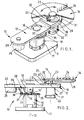
- a display device 10 comprises a base 11, a first rotatable member 12 mounted on the base 11 for rotation relative thereto about a first axis of rotation 13, and a second rotatable member 14 mounted on the first rotatable member 12 for rotation relative thereto about a second axis of rotation 15.
- the first rotatable member 12 is mounted on the base 11 by means of an electric motor 16 whose casing 17 is mounted on the base 11.
- the first rotatable member 12 is attached intermediate its ends 19 and 20 to the rotor shaft 16′ of the motor 16 by means of a socket 18.
- the socket 18 fittably receives an end of the shaft 16′ and is a force fit in an aperture in the first rotatable member 12.
- the second rotatable member 14 is of disc shape and attached at its centre to the end 19 of the first rotatable member 12 by means of an electric motor 21.
- a casing 22 of the motor 21 is attached to the underside of the first rotatable member 12, the rotor shaft 21′ of the motor 21 projecting through an aperture in the first rotatable member 12.
- the second rotatable member 14 is attached to the shaft 21′ by a socket 23.
- the socket 23 fittably receives an end of the shaft 21′ and is a force fit in a central aperture in the second rotatable member 14.
- the second rotatable member 14 carries an illumination device in the form of a plurality of light-emitting diodes 24.
- a balance weight 25 is attached to the opposite end 20 of the first rotatable member 12.
- a control circuit for the device 10 comprises a control module (not shown) connected to first and second control parts (the former is not shown and the latter is designated as 26 in Figure 2).
- the control module may be a computer, a microprocessor-based controller or music output device.
- the first part of the control circuitry controls the speed of rotation of the two motors 16 and 21. Both the control module and the first control part are preferably separate from the base 11 and the rotatable members 12 and 14, and are electrically connected to annular slip rings 33 and 37 mounted on the motor 16.
- the second part 26 of the control circuitry controls the switching of the light-emitting diodes 24 in synchronism with the speed of rotation of the motors 16 and 21, and is mounted on the underside of the second rotatable member 14.
- the speed of the motors 16 and 21 and the switching or switching frequency of the light-emitting diodes 24 are synchronised, for example, to enable the generation of a constant light display pattern whilst varying the speed of rotation of the motors, the control circuit speeding up the switching of the light emitting diodes in order to maintain the light display pattern steady as the speed of rotation of the motors is increased.
- the second part 26 of the control circuitry is electrically connected to the control module by means of two sets of sliding contacts 27 and 28 provided respectively between the first and second rotatable members 12 and 14, and the first rotatable member 12 and the base 11.
- the two rotor shafts 16′ and 21′ of the motors provide a return path to the electrical connection.
- the sliding contacts 27 comprise a slip ring 29 and an electrically conductive brush 30 slidable on the slip ring 29.
- the slip ring 29 is mounted on a plate 31 on the end 19 of the first rotatable member 12.
- the brush 30 is mounted on and depends from the underside of the second rotatable member 14 by means of an electrically conductive leaf spring 32.
- the sliding contacts 28 comprise the slip ring 33, and an electrically conductive brush 34 slidable on the slip ring 33.
- the slip ring 33 is mounted on a plate 35 on the upper end of the motor casing 17.
- the brush 34 is mounted on and depends from the underside of the first rotatable member 12 by means of an electrically conductive leaf spring 36.
- Terminals of the motor 21 are connected to the first part of the control circuitry by means of the slip ring 37 and an electrically conductive brush 38 slidable on the slip ring 37.
- the slip ring 38 is mounted on the plate 35, and the brush 38 is mounted on and depends from the underside of the first rotatable member 12 by means of an electrically conductive leaf spring 39.
- the rotor shaft 16′ of the motor 16 provides a return path to the electrical connection.
- Terminals of the motor 16 are electrically connected to the first part of the control circuitry by electrical leads.
- FIG 3 shows a second embodiment of a display device 10 a which is similar in operation and construction to the device 10 of Figure 1 but eliminates the need for the motor 21.
- the second rotatable member 14 is rotatably mounted on the first rotatable member 12 by means of a shaft 42.
- a socket 42 a is a force fit in a central aperture in and supports the second rotatable member 14, the lower end of the socket 42 a bearing on the upperside of the first rotatable member 12.
- Transmission means 41 is provided to transmit the rotational drive of the first rotatable member 12 to the second rotatable member 14.
- the transmission means 41 comprises two pulleys 43 and 44 mounted respectively on the rotor shaft 16′ of the motor 16 and the shaft 42, and a belt 45 connecting the two pulleys 43 and 44.
- a tubular spacer 42 b is mounted on the shaft 42 between the first rotatable member 12 and the pulley 44 to avoid any axial movement of the second rotatable member 14.
- FIG. 4 shows a third embodimemt of a display device 10 b similar in construction and operation to the device 10 of Figures 1 and 2.
- an illumination device comprising a plurality of light-emitting diodes 24′ is also provided on the end 20 of the rotatable member 12.
- These light-emitting diodes 24′ are controlled by a part 26 a of the second part 26 of the control circuit mounted on the underside of the first rotatable member 12.
- the first rotatable member 12 may be balanced by shifting the supporting position on the motor 16 towards the end 19.
- Figure 5 shows a fourth embodiment of a display device 10 c in which an additional second rotatable member 14′, similar in construction and operation to the existing second rotatable member 14, is provided at the opposite end 20 of the first rotatable member 12.
- Figure 6 shows a fifth embodiment of a display device 10 d in which an illumination device comprising a plurality of mirrors 46 is provided on the second rotatable member 14.
- a fixed light source comprising a plurality of light bulbs 47 is provided adjacent to the mirrors 46 so that the light from the light bulbs 47 is reflected by the mirrors 46 to generate a light display pattern.
- Light generated by the switching of the plurality of light bulbs 47 is reflected by the mirrors 46 to generate a light display pattern.
- the switching of the plurality of light bulbs 47 is controlled by the second part of the control circuitry in synchronism with the speed of rotation of the motors 16 and 21.
- the motors 16 and 21 for rotating repsectively the first and second rotatable members 12 and 14 are both mounted on the base 11.
- the rotational drive of the motor 21 is transmitted to the second rotatable member 14 by means of a gear train 48.
- the gear train 48 comprises a gear wheel 48 a mounted on the rotor shaft 21′ of the motor 21, a gear wheel 48 b mounted on an axial shaft 42′ of the second rotatable member 14, and reduction gears 48 c mounted on a sleeve 48 d rotatably mounted on the rotor shaft 16′ of the motor 16 and connecting the two gear wheels 48 a and 48 b .
- Figure 7 shows a sixth embodiment of a display device 10 e in which the first rotatable member 12 is a closed cylinder comprising two end walls 12 a and 12 b and a cylindrical side wall 12 c connecting the two end walls 12 a and 12 b .
- the motor 16 is attached to the base 11.
- the first rotatable member 12 is attached to the rotor shaft 16′ of the motor 16 at the centres of the two end walls 12 a and 12 b .
- the motor 21 is mounted on the outer side of the end wall 12 b .
- the rotor shaft 21′ of the motor 21 extends through the end wall 12 b with its remote end supporting the second rotatable member 14 an aperture 49 in the opposite end wall 12 a .
- a plurality of apertures 50 are provided in the second rotatable member 14, in each of which a lens 51 is mounted.
- a plurality of light bulbs 52 are mounted on the inner side of the end wall 12 b behind the second rotatable member 14. The switching of the light bulbs 52 is controlled by the second part of the control circuitry in synchronism with the speed of rotation of the motors 16 and 21. Light from the bulbs 52 is transmitted by the lenses 51 onto a screen 53 provided in front of the device 10 c . Hence a light display pattern is generated on the screen 53.
- An alternative to this embodiment is to have the apertures 50 left empty. In this case the light from the light bulbs 52 will pass through the apertures 50 and fall directly onto the screen 53.
- this embodiment is also capable of generating a light display pattern when viewed directly.
- Figures 8 and 9 show a seventh embodiment of a display device 10 g having a single rotatable member 12′ mounted for rotation about an axis of rotation 13′ on and relative to a base 11′ by means of an electric motor 16 a
- the construction of this device 10 g is similar to that of the device 10 b shown in Figure 4 except that the second rotatable member 14 and the related parts thereof are absent.
- the rotatable member 12′ is a circular disc and carries a plurality of light-emitting diodes 53.
- a control circuit having a control module (not shown) is electrically connected to a first part (not shown) and a second part 26.
- the first and second parts control respectively the speed of rotation of the motor 16 a and the switching of the light emitting diodes 53, the second part 26′ being mounted on the underside of the rotatable member 12′.
- the plurality of light-emitting diodes 53 is divided into two groups 53 a and 53 b .
- the light-emitting diodes 53 a are located in a radial direction to produce an arcuate light display pattern about the axis of rotation 13′ of the rotatable member 12′.
- the light-emitting diodes 53 b are located in a circular manner about an axis 15′ offset at a distance from the axis of rotation 13′.
- the diodes 53 b are switched in a circular sequential order in either direction to simulate an imaginary diode rotating about the axis 15′ which is itself being rotated by the rotatable member 12′ when the device 10 g operates.
- the diodes 53 b are capable of producing a light display pattern similar to that produced by the diodes 24 of the devices 10, and 10 a to 10 f .
- the light-emitting diodes 24 in the device embodiments 10, 10 a to 10 e , and 10 g may be mounted at different heights on respective rotatable members 12 and 14 so that three-dimensional light display patterns will be generated when the devices operate.
- FIG 11 shows a ninth embodiment of a display device 10 h , in which the rotatable members 12 and ]4 are driven by belts by respective electric motors 16 and 21.
- rotatable member 12 is in the form of a pulley about which is located a drive belt 54 which passes around a pulley 43 of motor 16.
- Rotatable member 14 is driven by motor 21 via drive belt 55, intermediate double pulley 56 located on the axis of rotation of rotatable member 12, drive belt 57 and pulley 58 located on the axis of rotation of rotatable member 14.
- Electric current is supplied to light-emitting diodes 53 of rotatable member 14 via stacks of slip rings 59, 60 mounted respectively on the axes of rotation of rotatable members 12 and 14 and electrically interconnected by means of electrically conductive leaf springs 61 mounted on a pillar 62 upstanding from rotatable member 12.
- the rotatable member 14 is in the form of a four-limbed cross (not shown), each arm of the cross and the central part thereof bearing the light-emitting diodes 53.
- Figure 12 shows a tenth embodiment of a display device 10; similar to the embodiment of Figure 11, but having two rotatable members 14, 14′.
- a triple pulley 63 relays drive via drive belts to both rotatable members 14, 14′ from motor 21.
- Electric current is supplied to the light-emitting diodes 53 of rotatable member 14′ from slip rings 59 to slip rings 60′ via further pillar-mounted electrically conductive leaf springs (not shown).
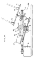
- Figure 13 shows an eleventh embodiment of a display device 10 j , similar to that of Figure 11, but in which the axis of rotation of rotatable member 14 is non-parallel to the axis of rotation of rotatable member 12.
- Electric current is supplied to lights 64 via a stack of slip rings 60 electrically connected to slip rings 59 by means of electrically conductive brushes 65, leads 66 and electrically conductive brushes 67.
- Drive is transmitted from pulley 58 to shaft 42 of rotatable member 14 via tubular rubber coupling 42A.
- Figure 14 shows a twelfth embodiment of a display device 10 k .
- rotatable member 12 is annular and is supported on shaft 68 by a boss 69 of a diametrical arm 70 of rotatable member 12.
- a secondary arm 71 extends transversely of boss 69 and carries a transverse support 72 supporting at one end thereof motor 21 and at the other end thereof rotatable member 14.
- Electric current is supplied to motor 21 via slip rings 59 by electrical connections (not shown) in arms 70, 71. Electric current is supplied to lights 73 of rotatable member 14 via slip rings 59 and slip rings 60.
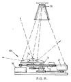
- Figure 15 shows an embodiment of a display device 10 l , similar to that of Figure 11 but in which rotatable member 14 is in the form of an upwardly convex member 74. On the convex surface of member 74 a plurality of mirrors 75 is mounted, which may be of different colours to each other, to reflect light from an external source 76.
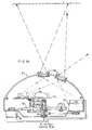
- Figure 16 shows in cross-section a complete display device, generally in accordance with the embodiment of Figure 11. It will be seen that the device of Figure 16 incorporates a dome or lid 77 which may be part-spherical. Incorporated into the dome or lid 77 is a plurality of lenses 78 adapted to modify the way in which light from lamps 79 is distributed.
- Figure 17 shows an embodiment of a display device 10 m , somewhat similar to that of Figure 11.
- light from a single light source 80 is directed along a folded path 81 by means of mirrors 82, 83, 84, 85, 86 onto a series of further mirrors 87 mounted on rotatable member 14 and constituting in this embodiment the illumination means of the present invention.
- the light source 80 may, if desired, be a source of normal light or of coherent light, e.g. a laser.
- circuitry for controlling a relatively simple embodiment of a display device according to the present invention is shown.
- the motor 16 for driving the rotatable member 12 (not shown) is controlled by a manually operable motor speed control 88.
- the motor 21 for the rotatable member 14 (not shown) is controlled by a motor speed control 89.
- This motor speed control 89 receives as an input a music or voice signal from input 90 which signal is amplified by band pass amplifier 91.
- the speed of the motor 21 is controlled by the motor speed control 89 in accordance with the level of the received music or voice signal.
- the lamps or light-emitting diodes 92 which constitute the illumination means in this embodiment are controlled by a panel control circuit 93.
- the panel control circuit 93 receives as an input the amplified music or voice signal from band pass amplifier 91 and feeds it as a digitised power and data signal via a buffer 94 to a decoder 95.
- the decoder 95 switches the lamps or light-emitting diodes 92 on and off in parallel by periodically applying, via a buffer 96, voltage V+ in accordance with the data signal derived from the amplified music or voice signal.
- the bandwidth and/or pass frequency of the band pass amplifier 91 may be adjusted by manual adjustment means (not shown).
- the display device of the present invention be provided with four separate means for adjusting the output or display of the device.
- a combined power ON/OFF and speed controller for motor 16 for motor 16.
- the speed control may be arranged so that it adjusts the initial speed ratio between motors 16 and 21, e.g. so that in use a display device may be adjusted initially to produce small circular patterns.
- a sensitivity control for adjusting the sensitivity of the display device to an input music or voice signal.
- each LED can create one individual light pattern Theoretically twelve LEDs can create a total of 212 combinations.
- a 'scan' control will generally be provided to adjust the time period over which an LED pattern changes to another LED pattern.
- a flash control for adjusting the flash rate of the lamps or LEDs.
- the lights may either appear as periodic dots or as continuous pattern.
- a display device as hereinbefore described give a planetary or circular motion to an illumination device to produce a light display pattern, such pattern preferably being a line pattern.
- the pattern is determined by the speed of rotation of the motors driving respective rotatable members, and the switching of respective illumination devices on respective rotatable members.
- illumination device used in the specification includes a light emitter such as a light-emitting diode, a light bulb or a neon tube, a light reflector such as a mirror, and a light transmitter such as a lens.
- the display device may be programmed, for example , to generate numerals, alphabets and geometrical figures for educational purposes. If a musical device be used in the control circuitry, the display device may give visual effect to the music.
Landscapes
- Engineering & Computer Science (AREA)
- Physics & Mathematics (AREA)
- Computer Hardware Design (AREA)
- General Physics & Mathematics (AREA)
- Theoretical Computer Science (AREA)
- General Engineering & Computer Science (AREA)
- Illuminated Signs And Luminous Advertising (AREA)
Applications Claiming Priority (2)
| Application Number | Priority Date | Filing Date | Title |
|---|---|---|---|
| GB878718119A GB8718119D0 (en) | 1987-07-30 | 1987-07-30 | Display device |
| GB8718119 | 1987-07-30 |
Publications (2)
| Publication Number | Publication Date |
|---|---|
| EP0301870A2 true EP0301870A2 (fr) | 1989-02-01 |
| EP0301870A3 EP0301870A3 (fr) | 1990-02-14 |
Family
ID=10621574
Family Applications (1)
| Application Number | Title | Priority Date | Filing Date |
|---|---|---|---|
| EP88306978A Withdrawn EP0301870A3 (fr) | 1987-07-30 | 1988-07-28 | Dispositif d'affichage |
Country Status (5)
| Country | Link |
|---|---|
| US (1) | US5041947A (fr) |
| EP (1) | EP0301870A3 (fr) |
| JP (1) | JPH01105991A (fr) |
| CN (1) | CN1030990A (fr) |
| GB (2) | GB8718119D0 (fr) |
Cited By (7)
| Publication number | Priority date | Publication date | Assignee | Title |
|---|---|---|---|---|
| WO1998059333A1 (fr) * | 1997-06-21 | 1998-12-30 | Adflash Limited | Systeme d'affichage |
| WO2000014704A1 (fr) * | 1998-09-03 | 2000-03-16 | Yingui Zhou | Technique de formation d'image a balayage de spot et appareil correspondant |
| FR2803771A1 (fr) * | 2000-01-18 | 2001-07-20 | Alternateurs Volants | Dispositif d'impression de trace(s) lumineux |
| WO2003063477A1 (fr) * | 2002-01-23 | 2003-07-31 | Seos Limited | Appareil d'eclairage |
| WO2006021788A1 (fr) | 2004-08-26 | 2006-03-02 | Litelogic Limited | Dispositif d'affichage |
| FR2912244A1 (fr) * | 2007-02-02 | 2008-08-08 | Peugeot Citroen Automobiles Sa | "dispositif d'affichage pour vehicule automobile" |
| WO2019117907A1 (fr) * | 2017-12-14 | 2019-06-20 | Hewlett-Packard Development Company, L.P. | Substrats rotatifs ayant des diodes électroluminescentes (del) |
Families Citing this family (81)
| Publication number | Priority date | Publication date | Assignee | Title |
|---|---|---|---|---|
| US5224901A (en) * | 1992-06-09 | 1993-07-06 | The Walt Disney Company | Apparatus and method for displaying an anamorphic illusion |
| US6590502B1 (en) | 1992-10-12 | 2003-07-08 | 911Ep, Inc. | Led warning signal light and movable support |
| GB2272791A (en) * | 1992-11-24 | 1994-05-25 | Lawford Delroy Marks | Revolving information displays |
| JPH06301349A (ja) * | 1993-04-12 | 1994-10-28 | Yoshiro Nakamatsu | 移動バーチャル表示装置 |
| IL106351A0 (en) * | 1993-07-14 | 1993-11-15 | Scitex Corp Ltd | Video display apparatus |
| US5607217A (en) * | 1993-10-26 | 1997-03-04 | Hobbs, Ii; James C. | Illumination system |
| US5422796A (en) * | 1993-12-20 | 1995-06-06 | Peebles; Sheon J. | Light twirler wand |
| DK173462B1 (da) * | 1995-09-14 | 2000-11-27 | Lego As | Byggeelement med indbygget lyskilde samt konstruktionsbyggesæt omfattende et byggeelement med indbygget lyskilde |
| US5791966A (en) * | 1996-02-09 | 1998-08-11 | Noise Toys, Inc. | Rotating toy with electronic display |
| HUP9602626A3 (en) * | 1996-09-25 | 1999-04-28 | Szekeres Peter | Rotation display |
| US5931716A (en) * | 1997-06-09 | 1999-08-03 | Hopkins; Lloyd M. | Illuminated flying toy |
| US6278419B1 (en) * | 1997-06-26 | 2001-08-21 | Light Spin Ltd. | Moving display |
| NL1007062C2 (nl) * | 1997-09-17 | 1999-03-18 | Trade International Trading | Display-inrichting. |
| GB2330679B (en) | 1997-10-21 | 2002-04-24 | 911 Emergency Products Inc | Warning signal light |
| US6193384B1 (en) | 1998-03-18 | 2001-02-27 | Buckminster G. Stein | Ceiling fan sign |
| IL140035A0 (en) * | 1998-06-03 | 2002-02-10 | United Syndicate Insurance Ltd | A high definition volumetric display system |
| GB2331174B (en) * | 1998-10-03 | 2000-12-06 | Bissell Thomas James Durell | Display device |
| GB9903113D0 (en) * | 1999-02-11 | 1999-04-07 | Mgx International Ltd | Programmable display device |
| US6462669B1 (en) | 1999-04-06 | 2002-10-08 | E. P . Survivors Llc | Replaceable LED modules |
| US6614359B2 (en) | 1999-04-06 | 2003-09-02 | 911 Emergency Products, Inc. | Replacement led lamp assembly and modulated power intensity for light source |
| US6705745B1 (en) | 1999-06-08 | 2004-03-16 | 911Ep, Inc. | Rotational led reflector |
| WO2000074972A1 (fr) | 1999-06-08 | 2000-12-14 | 911 Emergency Products, Inc. | Assemblage lumineux a del en bande |
| US6700502B1 (en) | 1999-06-08 | 2004-03-02 | 911Ep, Inc. | Strip LED light assembly for motor vehicle |
| US6367949B1 (en) | 1999-08-04 | 2002-04-09 | 911 Emergency Products, Inc. | Par 36 LED utility lamp |
| US6547410B1 (en) * | 2000-07-28 | 2003-04-15 | 911 Emergency Products, Inc. | LED alley/take-down light |
| US6373511B1 (en) * | 1999-11-26 | 2002-04-16 | Ivi Checkmate Corp. | Combination terminal and printer |
| TW475760U (en) * | 2000-03-01 | 2002-02-01 | Jin-Suei Lin | Electronic light emitting display of planar swinging type |
| US20030150398A1 (en) * | 2000-03-15 | 2003-08-14 | Barbara Nathanson | Pettoy |
| US6505576B2 (en) * | 2000-03-15 | 2003-01-14 | Barbara Nathanson | Pet toy |
| US6325690B1 (en) | 2000-07-06 | 2001-12-04 | Webb Nelson | Toy top with message display and associated method of initiating and synchronizing the display |
| US7439847B2 (en) | 2002-08-23 | 2008-10-21 | John C. Pederson | Intelligent observation and identification database system |
| WO2002041276A2 (fr) * | 2000-11-15 | 2002-05-23 | Snowy Village, Inc. | Avertisseur lumineux a base de diodes electroluminescentes et systeme de communication |
| US8188878B2 (en) | 2000-11-15 | 2012-05-29 | Federal Law Enforcement Development Services, Inc. | LED light communication system |
| JP3910359B2 (ja) * | 2000-11-24 | 2007-04-25 | 株式会社小糸製作所 | 車輌用灯具 |
| GB2382211A (en) * | 2001-09-15 | 2003-05-21 | Hyena Games Ltd | Display device for a bicycle wheel |
| FR2831382B1 (fr) * | 2001-10-19 | 2008-12-26 | Valeo Vision | Dispositif d'eclairage ou de signalisation a diodes electroluminescentes |
| US20030174494A1 (en) * | 2002-03-14 | 2003-09-18 | Mark Chernick | Illuminated device containing spinning electroluminescent wire |
| DE10313023B4 (de) * | 2003-03-24 | 2006-02-23 | GTG Gesellschaft für elektronische Geräte mbH | Vorrichtung zur audiovisuellen Präsentation von Ton und Bild |
| TW578310B (en) * | 2003-04-02 | 2004-03-01 | Au Optronics Corp | Low temperature poly silicon thin film transistor and method of forming poly silicon layer of the same |
| US20050001562A1 (en) * | 2003-07-02 | 2005-01-06 | 911Ep, Inc. | LED compensation circuit |
| US20060094327A1 (en) * | 2004-09-20 | 2006-05-04 | Mark Chernick | Waving illuminated novelty device with spinning light sources |
| JP2006271635A (ja) * | 2005-03-29 | 2006-10-12 | Daiichi Shokai Co Ltd | 遊技機 |
| JP2006271631A (ja) * | 2005-03-29 | 2006-10-12 | Daiichi Shokai Co Ltd | 遊技機 |
| JP2006271626A (ja) * | 2005-03-29 | 2006-10-12 | Daiichi Shokai Co Ltd | 遊技機 |
| JP2006271621A (ja) * | 2005-03-29 | 2006-10-12 | Daiichi Shokai Co Ltd | 遊技機 |
| JP2006271625A (ja) * | 2005-03-29 | 2006-10-12 | Daiichi Shokai Co Ltd | 遊技機 |
| US20070103545A1 (en) * | 2005-11-09 | 2007-05-10 | Digital Video Media, L.L.C. | 360 Degree display |
| RU2378567C2 (ru) * | 2005-11-15 | 2010-01-10 | Владимир Павлович Торчигин | Устройство для осуществления механической развертки при формировании изображения путем модуляции движущихся источников света |
| CN1852445B (zh) * | 2006-05-15 | 2010-08-04 | 郁有华 | 平面、立体两用显示器 |
| FR2912246B1 (fr) * | 2007-02-02 | 2009-03-06 | Peugeot Citroen Automobiles Sa | "dispositif d'affichage pour vehicule automobile" |
| US9100124B2 (en) | 2007-05-24 | 2015-08-04 | Federal Law Enforcement Development Services, Inc. | LED Light Fixture |
| US9258864B2 (en) | 2007-05-24 | 2016-02-09 | Federal Law Enforcement Development Services, Inc. | LED light control and management system |
| WO2008148039A1 (fr) | 2007-05-24 | 2008-12-04 | Federal Law Enforcement Development Services, Inc. | Système de communication à éclairage par del |
| US9294198B2 (en) | 2007-05-24 | 2016-03-22 | Federal Law Enforcement Development Services, Inc. | Pulsed light communication key |
| US9414458B2 (en) | 2007-05-24 | 2016-08-09 | Federal Law Enforcement Development Services, Inc. | LED light control assembly and system |
| US9455783B2 (en) | 2013-05-06 | 2016-09-27 | Federal Law Enforcement Development Services, Inc. | Network security and variable pulse wave form with continuous communication |
| US11265082B2 (en) | 2007-05-24 | 2022-03-01 | Federal Law Enforcement Development Services, Inc. | LED light control assembly and system |
| FI120326B (fi) * | 2008-08-14 | 2009-09-15 | Abb Oy | Informaation esittäminen liikkuvissa kohteissa ja taajuusmuuttaja |
| US8157383B2 (en) * | 2008-10-01 | 2012-04-17 | The United States Of America As Represented By The Secretary Of The Army | System for displaying images and/or information on aircraft blades and method thereof |
| US8206007B2 (en) * | 2009-02-10 | 2012-06-26 | Richard Charles Lynn | Vibrating LED lighting device |
| US8890773B1 (en) | 2009-04-01 | 2014-11-18 | Federal Law Enforcement Development Services, Inc. | Visible light transceiver glasses |
| US9186595B1 (en) | 2010-08-13 | 2015-11-17 | Mattel, Inc. | Toy with persistance of view components |
| US9658379B2 (en) | 2010-12-15 | 2017-05-23 | Thomas Mark Spangler | Fiber optic display apparatus and methods of osillating illuminated optical fibers |
| US8543505B2 (en) | 2011-01-14 | 2013-09-24 | Federal Law Enforcement Development Services, Inc. | Method of providing lumens and tracking of lumen consumption |
| US20130126697A1 (en) * | 2011-11-17 | 2013-05-23 | Steven Harris | Rotating car wheel display |
| CN103853074B (zh) * | 2012-11-28 | 2016-05-18 | 中科英华湖州工程技术研究中心有限公司 | 程序继电器装置 |
| US9265112B2 (en) | 2013-03-13 | 2016-02-16 | Federal Law Enforcement Development Services, Inc. | LED light control and management system |
| US9890938B2 (en) | 2016-02-08 | 2018-02-13 | Gemmy Industries Corp. | Decorative light |
| US10400966B2 (en) | 2013-12-31 | 2019-09-03 | Gemmy Industries Corp. | Decorative lights and related methods |
| US20150198941A1 (en) | 2014-01-15 | 2015-07-16 | John C. Pederson | Cyber Life Electronic Networking and Commerce Operating Exchange |
| US20170175953A1 (en) * | 2014-02-11 | 2017-06-22 | Philips Lighting Holding B.V. | Tubular lighting fixture |
| CN204592889U (zh) * | 2015-05-27 | 2015-08-26 | 阳江市纳丽德工贸有限公司 | 照明装置 |
| US20170046950A1 (en) | 2015-08-11 | 2017-02-16 | Federal Law Enforcement Development Services, Inc. | Function disabler device and system |
| CN105185192B (zh) * | 2015-09-25 | 2018-06-19 | 吉林工商学院 | 用于英语课堂的齿轮式随机点学号系统 |
| US9989229B2 (en) | 2015-12-07 | 2018-06-05 | Ryan R. PIEPER | System, apparatus and method for a dimmable circuit |
| US10234118B2 (en) | 2016-02-08 | 2019-03-19 | Gemmy Industries Corp. | Decorative light |
| USD791381S1 (en) | 2016-02-08 | 2017-07-04 | Gemmy Industries Corp. | Decorative light |
| US10379435B2 (en) * | 2016-11-10 | 2019-08-13 | Shai Seger | Self-orienting stroboscopic animation system |
| CN112334704A (zh) * | 2018-04-09 | 2021-02-05 | 恩塔设计公司 | 具有移动图案照明的灯具 |
| CN111105724A (zh) * | 2019-11-30 | 2020-05-05 | 苏州浪潮智能科技有限公司 | 智能存储系统 |
| KR102562079B1 (ko) * | 2021-06-15 | 2023-08-02 | (주)거노코퍼레이션 | 회전식 엘이디 디스플레이 장치 |
Family Cites Families (23)
| Publication number | Priority date | Publication date | Assignee | Title |
|---|---|---|---|---|
| USRE21202E (en) * | 1939-09-05 | Changeablextght | ||
| GB448692A (en) * | 1935-11-04 | 1936-06-15 | Richard Howard Minns | Improvements in neon signs and the like |
| GB709446A (en) * | 1950-08-23 | 1954-05-26 | Henri Aron Stark | Improvements in advertising or like devices |
| GB737821A (en) * | 1953-05-05 | 1955-10-05 | Henryk Sarnicki | Apparatus for automatically displaying a succession of advertisements or the like |
| GB1061381A (en) * | 1962-08-21 | 1967-03-08 | John Chapman Rudge | Improvements in and relating to luminous signs |
| GB1007257A (en) * | 1962-10-24 | 1965-10-13 | John Eric Winstanley | Improvements in or relating to apparatus for producing coloured light effects |
| DE1472482A1 (de) * | 1965-06-23 | 1969-03-13 | Brunner Horst Gottfried | Geraete und Arten zur Erzeugung von Farbwirkungen und sich aendernden Lichtreflexen,insbesondere in Wohnraeumen |
| US3531636A (en) * | 1968-06-26 | 1970-09-29 | William B Birch | Ornamental light fixture |
| GB1311663A (en) * | 1969-03-06 | 1973-03-28 | Payne S B | Picture activation |
| GB1241369A (en) * | 1969-12-18 | 1971-08-04 | Standard Telephones Cables Ltd | Display arrangement |
| US3707790A (en) * | 1970-03-31 | 1973-01-02 | M Jaffe | Illuminated display device |
| US3793755A (en) * | 1971-07-15 | 1974-02-26 | W Gersch | Illuminated display apparatus |
| US3751654A (en) * | 1971-08-18 | 1973-08-07 | P Grebinar | Rotational lighting system |
| US3760176A (en) * | 1971-09-24 | 1973-09-18 | L Trop | Light machine |
| GB1420982A (en) * | 1973-05-09 | 1976-01-14 | Zand J S | Advertising or lighting fixture |
| US3949350A (en) * | 1974-08-07 | 1976-04-06 | Smith Richard D | Ornamental lighting device |
| US4298868A (en) * | 1980-04-11 | 1981-11-03 | Spurgeon John R | Electronic display apparatus |
| US4338547A (en) * | 1980-06-19 | 1982-07-06 | Mccaslin Robert E | Apparatus and method for generating light designs |
| GB2093617B (en) * | 1981-02-24 | 1985-05-15 | Lock Trevor John | Visual display device |
| EP0082235A1 (fr) * | 1981-12-22 | 1983-06-29 | L.B. AMPLILUX s.r.l. | Support tournant pour projecteurs et dômes à couleurs variées et à mouvements indépendants pour effets scéniques |
| US4817163A (en) * | 1986-02-17 | 1989-03-28 | Erich Stastny | Loud-speaker combined with a device for producing lighting effects |
| US4809584A (en) * | 1987-07-07 | 1989-03-07 | Forrest David M | Music translation device |
| US4858079A (en) * | 1987-11-16 | 1989-08-15 | Tomy Kogyo Co., Inc. | Light projecting toy musical box |
-
1987
- 1987-07-30 GB GB878718119A patent/GB8718119D0/en active Pending
-
1988
- 1988-07-22 GB GB08817468A patent/GB2207796A/en not_active Withdrawn
- 1988-07-28 EP EP88306978A patent/EP0301870A3/fr not_active Withdrawn
- 1988-07-29 JP JP63190480A patent/JPH01105991A/ja active Pending
- 1988-07-30 CN CN88104753A patent/CN1030990A/zh active Pending
-
1990
- 1990-06-22 US US07/541,191 patent/US5041947A/en not_active Expired - Fee Related
Cited By (13)
| Publication number | Priority date | Publication date | Assignee | Title |
|---|---|---|---|---|
| WO1998059333A1 (fr) * | 1997-06-21 | 1998-12-30 | Adflash Limited | Systeme d'affichage |
| WO2000014704A1 (fr) * | 1998-09-03 | 2000-03-16 | Yingui Zhou | Technique de formation d'image a balayage de spot et appareil correspondant |
| FR2803771A1 (fr) * | 2000-01-18 | 2001-07-20 | Alternateurs Volants | Dispositif d'impression de trace(s) lumineux |
| US7021795B2 (en) | 2002-01-23 | 2006-04-04 | Seos Limited | Illumination apparatus |
| WO2003063477A1 (fr) * | 2002-01-23 | 2003-07-31 | Seos Limited | Appareil d'eclairage |
| GB2388993A (en) * | 2002-01-23 | 2003-11-26 | Seos Ltd | Illumination apparatus |
| GB2388993B (en) * | 2002-01-23 | 2005-09-21 | Seos Ltd | Illumination apparatus |
| WO2006021788A1 (fr) | 2004-08-26 | 2006-03-02 | Litelogic Limited | Dispositif d'affichage |
| EA010482B1 (ru) * | 2004-08-26 | 2008-10-30 | Лителоджик Лимитед | Дисплей |
| US8013806B2 (en) | 2004-08-26 | 2011-09-06 | Litelogic Ip Limited | Display device |
| FR2912244A1 (fr) * | 2007-02-02 | 2008-08-08 | Peugeot Citroen Automobiles Sa | "dispositif d'affichage pour vehicule automobile" |
| WO2019117907A1 (fr) * | 2017-12-14 | 2019-06-20 | Hewlett-Packard Development Company, L.P. | Substrats rotatifs ayant des diodes électroluminescentes (del) |
| US11423812B2 (en) | 2017-12-14 | 2022-08-23 | Hewlett-Packard Development Company, L.P. | Rotatable substrates having micro-light emitting diodes (LEDs) |
Also Published As
| Publication number | Publication date |
|---|---|
| CN1030990A (zh) | 1989-02-08 |
| EP0301870A3 (fr) | 1990-02-14 |
| GB8718119D0 (en) | 1987-09-03 |
| GB8817468D0 (en) | 1988-08-24 |
| JPH01105991A (ja) | 1989-04-24 |
| US5041947A (en) | 1991-08-20 |
| GB2207796A (en) | 1989-02-08 |
Similar Documents
| Publication | Publication Date | Title |
|---|---|---|
| EP0301870A2 (fr) | Dispositif d'affichage | |
| US5029047A (en) | Lighted fiber optic mobile | |
| US10636389B2 (en) | Rotational display system | |
| US8284214B2 (en) | Rotational display system | |
| CN100510521C (zh) | 可实现位置遥控的照明装置 | |
| US4206495A (en) | Optical fiber light display | |
| WO1999010235A1 (fr) | Helicoptere pourvu d'un rotor gyroscopique et d'helices sur rotor pour assurer une poussee orientable | |
| US5269719A (en) | Light show mechanism | |
| US5842768A (en) | Signal light oscillating mechanism | |
| US4232304A (en) | Vibratory-rotary motion converters and display devices incorporating such converters | |
| WO1999041544A1 (fr) | Dispositif de pointage de faisceau | |
| CN210197068U (zh) | 环形转动装置 | |
| US4934712A (en) | Weighted objects with tether and means for twisting tether to raise and lower objects | |
| US6994605B2 (en) | Vibratory amusement device for producing concentric illuminated rings | |
| KR20010044267A (ko) | 비구면 거울을 이용한 3차원 영상 표시 장치 | |
| US1800054A (en) | Display mechanism | |
| EP1236194B1 (fr) | Systeme generateur d'ondes multicolores 3d ajustable | |
| US5676447A (en) | Signal light oscillating mechanism | |
| EP1477730A3 (fr) | Unité laser pour générer un rayon lumineux, convenant à la génération d'effets lumineux | |
| US1188118A (en) | Electric display device. | |
| JP2023516586A (ja) | ビデオプロジェクタ用のモータ駆動ブラケット | |
| CN222707934U (zh) | 一种模型视觉显示装置 | |
| CN112443803A (zh) | 活动火焰组件以及包括其的仿真火焰装置 | |
| CN113223401B (zh) | 一种太阳系八大行星动态模拟装置 | |
| US1550374A (en) | Electrically-illuminated sign |
Legal Events
| Date | Code | Title | Description |
|---|---|---|---|
| PUAI | Public reference made under article 153(3) epc to a published international application that has entered the european phase |
Free format text: ORIGINAL CODE: 0009012 |
|
| AK | Designated contracting states |
Kind code of ref document: A2 Designated state(s): AT BE CH DE ES FR IT LI NL SE |
|
| PUAL | Search report despatched |
Free format text: ORIGINAL CODE: 0009013 |
|
| 17P | Request for examination filed |
Effective date: 19891121 |
|
| AK | Designated contracting states |
Kind code of ref document: A3 Designated state(s): AT BE CH DE ES FR IT LI NL SE |
|
| 17Q | First examination report despatched |
Effective date: 19920415 |
|
| STAA | Information on the status of an ep patent application or granted ep patent |
Free format text: STATUS: THE APPLICATION IS DEEMED TO BE WITHDRAWN |
|
| 18D | Application deemed to be withdrawn |
Effective date: 19940708 |