EP0301940A1 - Dispositif limiteur de longueur de file pour chariots de transport - Google Patents
Dispositif limiteur de longueur de file pour chariots de transport Download PDFInfo
- Publication number
- EP0301940A1 EP0301940A1 EP88401860A EP88401860A EP0301940A1 EP 0301940 A1 EP0301940 A1 EP 0301940A1 EP 88401860 A EP88401860 A EP 88401860A EP 88401860 A EP88401860 A EP 88401860A EP 0301940 A1 EP0301940 A1 EP 0301940A1
- Authority
- EP
- European Patent Office
- Prior art keywords
- carriage
- trolleys
- barriers
- probe
- lever
- Prior art date
- Legal status (The legal status is an assumption and is not a legal conclusion. Google has not performed a legal analysis and makes no representation as to the accuracy of the status listed.)
- Granted
Links
- 230000004888 barrier function Effects 0.000 claims abstract description 19
- 239000000523 sample Substances 0.000 claims description 15
- 230000005484 gravity Effects 0.000 claims description 5
- 230000037431 insertion Effects 0.000 abstract 1
- 238000003780 insertion Methods 0.000 abstract 1
- 238000009434 installation Methods 0.000 description 4
- 230000006978 adaptation Effects 0.000 description 1
- 230000002411 adverse Effects 0.000 description 1
- 230000000694 effects Effects 0.000 description 1
- 238000005192 partition Methods 0.000 description 1
- 230000001681 protective effect Effects 0.000 description 1
- 238000011084 recovery Methods 0.000 description 1
- 230000000284 resting effect Effects 0.000 description 1
- 239000007787 solid Substances 0.000 description 1
Images
Classifications
-
- G—PHYSICS
- G07—CHECKING-DEVICES
- G07F—COIN-FREED OR LIKE APPARATUS
- G07F7/00—Mechanisms actuated by objects other than coins to free or to actuate vending, hiring, coin or paper currency dispensing or refunding apparatus
- G07F7/06—Mechanisms actuated by objects other than coins to free or to actuate vending, hiring, coin or paper currency dispensing or refunding apparatus by returnable containers, i.e. reverse vending systems in which a user is rewarded for returning a container that serves as a token of value, e.g. bottles
- G07F7/0618—Mechanisms actuated by objects other than coins to free or to actuate vending, hiring, coin or paper currency dispensing or refunding apparatus by returnable containers, i.e. reverse vending systems in which a user is rewarded for returning a container that serves as a token of value, e.g. bottles by carts
- G07F7/0636—Mechanisms actuated by objects other than coins to free or to actuate vending, hiring, coin or paper currency dispensing or refunding apparatus by returnable containers, i.e. reverse vending systems in which a user is rewarded for returning a container that serves as a token of value, e.g. bottles by carts in which the trolleys or carts are kept in a restricted zone such as a coral-like enclosure, or are passing a gate before use is possible
-
- A—HUMAN NECESSITIES
- A47—FURNITURE; DOMESTIC ARTICLES OR APPLIANCES; COFFEE MILLS; SPICE MILLS; SUCTION CLEANERS IN GENERAL
- A47F—SPECIAL FURNITURE, FITTINGS, OR ACCESSORIES FOR SHOPS, STOREHOUSES, BARS, RESTAURANTS OR THE LIKE; PAYING COUNTERS
- A47F10/00—Furniture or installations specially adapted to particular types of service systems, not otherwise provided for
- A47F10/02—Furniture or installations specially adapted to particular types of service systems, not otherwise provided for for self-service type systems, e.g. supermarkets
- A47F10/04—Furniture or installations specially adapted to particular types of service systems, not otherwise provided for for self-service type systems, e.g. supermarkets for storing or handling self-service hand-carts or baskets
-
- G—PHYSICS
- G07—CHECKING-DEVICES
- G07F—COIN-FREED OR LIKE APPARATUS
- G07F7/00—Mechanisms actuated by objects other than coins to free or to actuate vending, hiring, coin or paper currency dispensing or refunding apparatus
- G07F7/06—Mechanisms actuated by objects other than coins to free or to actuate vending, hiring, coin or paper currency dispensing or refunding apparatus by returnable containers, i.e. reverse vending systems in which a user is rewarded for returning a container that serves as a token of value, e.g. bottles
- G07F7/0618—Mechanisms actuated by objects other than coins to free or to actuate vending, hiring, coin or paper currency dispensing or refunding apparatus by returnable containers, i.e. reverse vending systems in which a user is rewarded for returning a container that serves as a token of value, e.g. bottles by carts
- G07F7/0627—Mechanisms actuated by objects other than coins to free or to actuate vending, hiring, coin or paper currency dispensing or refunding apparatus by returnable containers, i.e. reverse vending systems in which a user is rewarded for returning a container that serves as a token of value, e.g. bottles by carts in which the trolleys or carts are kept fixed or linked onto a rail or barrier
Definitions
- the invention relates to a device for limiting the length of the line for transport trolleys such as trolleys for large-scale stores, stations or air terminals, in which said trolleys are housed between two parallel guide barriers whose spacing is slightly greater than the overall width of said carriages.
- the present invention aims to obtain a safe, solid and economical queue limiting device, which does not require any adaptation of the carriages, and which applies as well for carts provided with lockers as for carts which do not have them.
- the device according to the invention is characterized in that it comprises at least one probe mounted on one of said barriers and cooperating with a part of the carriages during their introduction between the barriers, said probe being arranged so as to prohibit the passage of a new carriage when it is resting on an already inserted carriage.
- the probe When the line of carriages between the barriers is full, the probe remains in contact with the last carriage introduced which cannot be pushed further forward, and prevents the entry of a new carriage.
- the probe is constituted by one end of a lever with two arms oscillating around an axis integral with at least one of the barriers and being returned towards the member of the carriage with which it cooperates, the other end of said lever comprising a stop for said member.
- the stop prevents passage of the member of the following carriage. If the probe is not in contact with the member of a carriage, the stop is cleared by the tilting of the lever under the effect of the restoring force.
- the axis and horizontal and the lever is returned by gravity thanks to the difference in mass between its arms.
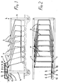
- the installation comprises two parallel barriers 1, one end of which is closed by a front partition 2 and between which can be housed carriages 3 which, in the example shown, can be successively embedded in one another to reduce the space requirement. length.
- the barriers 1 and 2 are carried by posts 4.
- the device 5 comprises a protective casing 6, secured to the post 4, allowing passage below the handle 7 of a carriage 3.
- the casing 6 contains a lever 8 articulated around a horizontal axis 9.
- the lever 8 comprises an anterior branch 10, the lower face of which comprises a boss or cam 11 which comes into contact with the handle 7 of a carriage 3 during the entry of this carriage between the barriers 1.
- the lever 8 further comprises a rear branch 12 whose lower face forms a stop 13.
- the respective masses of the arms 10 and 12 are such that the lever 8 is normally recalled by gravity clockwise (in Figure 1).
- the handle 7 of the last carriage 3 introduced does not cooperate with the probe 11 or else, if this handle 7 is in contact with the probe 11 it is possible to push the latter carriage 3 towards the interior by tightening the line.
- the lever 8 is tilted by gravity in a clockwise direction and the stop 13 is erased upwards, which allows the passage of the handle 7 of an additional carriage 3.
- the device according to the invention is particularly effective when the carriages 3 are provided with deposit systems of known type requiring complete embedding of a carriage at the end of a file to recover the deposit. Indeed, in the case of a complete queue, this recovery is not possible.
- the device of the invention also applies to carts not equipped with deposit systems since the user (or specialized personnel) is supposed to make the effort to bring the car back between the barriers 1.
- the probe 13 can be provided to cooperate with a part of the carriage 3 other than the handle 7, for example with a part of the chassis, a wheel yoke, a special insert on the carriage, etc.
- the pivot axis of the lever may be vertical.
- the probe 13 does not oppose the exit of the carriages 3 which push the probe 11 against the return force of the lever 8.
Landscapes
- Physics & Mathematics (AREA)
- General Physics & Mathematics (AREA)
- Control Of Position, Course, Altitude, Or Attitude Of Moving Bodies (AREA)
- Train Traffic Observation, Control, And Security (AREA)
- Handcart (AREA)
Abstract
Description
- L'invention concerne un dispositif limiteur de longueur de file pour chariots de transport tels que chariots de magasins grande surface, de gares ou d'aérogare, dans lequel lesdits chariots sont logés entre deux barrières de guidage parallèles dont l'écartement est légèrement supérieur à la largeur hors tout desdits chariots.
- Avec des installations de gestion de chariots de ce type, il arrive que, la longueur des barrières de guidage étant emplie de chariots, les usagers continuent à ajouter des chariots à la fin de la file, provoquant ainsi un débordement de la file. Ce débordement est dangereux pour les autres usagers, pour l'accès aux sorties de secours et pour la circulation des véhicules lorsque la file est formée dans un garage. En outre, il provoque des détériorations des chariots. Dans tous les cas, ce débordement contrarie la gestion du parc de chariots et implique que des chariots peuvent ne pas être disponibles sur une autre file.
- Pour pallier cet inconvénient, on a proposé divers systèmes de consignation de chariots liés à une barre de guidage, de sorte que la consigne ne peut être récupérée que si le chariot est ramené sur la barre, dont la capacité est limitée.
- Ces divers systèmes connus impliquent une consignation, qui n'est pas toujours souhaitée, et sont d'un prix de revient relativement élevés.
- La présente invention vise à obtenir un dispositif limiteur de file sûr, solide et économique, qui ne nécessite aucune adaptation des chariots, et qui s'applique aussi bien pour des chariots munis de consigneurs que pour des chariots qui n'en comportent pas.
- A cet effet, le dispositif selon l'invention est caractérisé par le fait qu'il comprend au moins un palpeur monté sur une desdites barrières et coopérant avec une partie des chariots lors de leur introduction entre les barrières, ledit palpeur étant agencé de manière à interdire le passage d'un nouveau chariot lorsqu'il est en appui sur un chariot déjà introduit.
- Lorsque la file de chariots entre les barrières est pleine, le palpeur reste en appui sur le dernier chariot introduit qui ne peut pas être poussé plus en avant, et interdit l'entrée d'un nouveau chariot.
- Dans une forme de réalisation préférée de l'invention, le palpeur est constitué par une extrémité d'un levier à deux bras oscillant autour d'un axe solidaire d'au moins une des barrières et étant rappelé vers l'organe du chariot avec lequel il coopère, l'autre extrémité dudit levier comportant une butée pour ledit organe. Lorsque le palpeur est en appui contre un organe du chariot, par exemple une poignée, la butée interdit le passage de l'organe du chariot suivant. Si le palpeur n'est pas en appui sur l'organe d'un chariot, la butée est effacée par le basculement du levier sous l'effet de la force de rappel.
- Avantageusement, l'axe et horizontal et le levier est rappelé par gravité grâce à la différence de masse entre ses bras. On obtient ainsi une solution extrèmement simple et robuste, évitant tout coincement.
- L'invention sera bien comprise à la lecture de la description suivante faite en se référant au dessin annexé dans lequel:
- - la figure 1 est une vue en élévation latérale d'une installation selon un exemple de réalisation de l'invention et
- la figure 2 est une vue de dessus de l'installation de la figure 1.
- L'installation comprend deux barrières parallèles 1 dont une extrémité est fermée par une cloison frontale 2 et entre lesquelles peuvent être logés des chariots 3 qui, dans l'exemple représenté, peuvent être encastrés successivement les uns dans les autres pour réduire l'encombrement en longueur. Les barrières 1 et 2 sont portées par des poteaux 4.
- L'un des poteaux 4 porte le dispositif limiteur 5 selon l'invention, qui est ainsi solidaire d'une barrière 1. Le dispositif 5 comprend un carter protecteur 6, solidaire du poteau 4, permettant le passage au-dessous de la poignée 7 d'un chariot 3. Le carter 6 contient un levier 8 articulé autour d'un axe horizontal 9. Le levier 8 comprend une branche antérieure 10 dont la face inférieure comporte un bossage ou came 11 qui entre en contact avec la poignée 7 d'un chariot 3 lors de l'entrée de ce chariot entre les barrières 1. Le levier 8 comporte en outre une branche postérieure 12 dont la face inférieure forme une butée 13. Les masses respectives des bras 10 et 12 sont telles que le levier 8 est normalement rappelé par gravité dans le sens des aiguilles d'une montre (sur la figure 1).
- Lorsque la file n'est pas complète, la poignée 7 du dernier chariot 3 introduit ne coopère pas avec le palpeur 11 ou bien, si cette poignée 7 est en contact avec le palpeur 11 il est possible de repousser ce dernier chariot 3 vers l'intérieur en resserrant la file. Le levier 8 est basculé par gravité dans le sens des aiguilles d'une montre et la butée 13 est effacée vers le haut, ce qui permet le passage de la poignée 7 d'un chariot 3 supplémentaire.
- Au contraire, si la file est complète, comme représenté au dessin, le levier 8 est maintenu, contre la force de gravité, par le contact entre le palpeur 11 et la poignée 7. La butée 13 est alors sur la trajectoire d'une poignée 7' d'un nouveau chariot (non représenté) qu'un utilisateur voudrait introduire, et ce chariot ne peut pas pénétrer complètement entre les barrières 1 et 2.
- Le dispositif selon l'invention est particulièrement efficace lorsque les chariots 3 sont munis de systèmes de consigne de type connus nécessitant un encastrement complet d'un chariot à l'extrémité d'une file pour récupérer la consigne. En effet, dans le cas d'une file complète, cette récupération n'est pas possible. Cependant, le dispositif de l'invention s'applique aussi aux chariots non équipés de systèmes de consigne puisque l'utilisateur (ou du personnel spécialisé) est censé faire l'effort de ramener le chariot entre les barrières 1.
- Le palpeur 13 peut être prévu pour coopérer avec une partie du chariot 3 autre que la poignée 7, par exemple avec une partie du chassis, une chape de roue, une pièce rapportée spéciale sur le chariot, etc. Selon le cas, l'axe de pivotement du levier pourra être vertical.
- Le palpeur 13 ne s'oppose pas à la sortie des chariots 3 qui repoussent le palpeur 11 contre la force de rappel du levier 8.
Claims (4)
Applications Claiming Priority (2)
| Application Number | Priority Date | Filing Date | Title |
|---|---|---|---|
| FR8710200A FR2618317B1 (fr) | 1987-07-20 | 1987-07-20 | Dispositif limiteur de longueur de file pour chariots de transport |
| FR8710200 | 1987-07-20 |
Publications (2)
| Publication Number | Publication Date |
|---|---|
| EP0301940A1 true EP0301940A1 (fr) | 1989-02-01 |
| EP0301940B1 EP0301940B1 (fr) | 1992-04-22 |
Family
ID=9353300
Family Applications (1)
| Application Number | Title | Priority Date | Filing Date |
|---|---|---|---|
| EP88401860A Expired - Lifetime EP0301940B1 (fr) | 1987-07-20 | 1988-07-19 | Dispositif limiteur de longueur de file pour chariots de transport |
Country Status (3)
| Country | Link |
|---|---|
| EP (1) | EP0301940B1 (fr) |
| DE (1) | DE3870347D1 (fr) |
| FR (1) | FR2618317B1 (fr) |
Families Citing this family (5)
| Publication number | Priority date | Publication date | Assignee | Title |
|---|---|---|---|---|
| DE59008851D1 (de) * | 1989-12-18 | 1995-05-11 | Peter Fuchs | Vorrichtung zur Begrenzung von Einkaufswagenreihen. |
| DE4115547A1 (de) * | 1991-05-13 | 1992-11-19 | Peter Fuchs | Vorrichtung zur begrenzung von einkaufswagenreihen |
| FR2682500A1 (fr) * | 1991-10-09 | 1993-04-16 | Nord Etudes Lt Sarl | Limiteur de file pour chariots a consigne. |
| EP0598142B1 (fr) * | 1992-11-17 | 1996-01-10 | Peter Fuchs | Dispositif limiteur de longueur de file pour chariots de supermarché |
| DE19814918C1 (de) | 1998-04-03 | 1999-07-29 | Siegel Geb Gmbh Co Kg | Aufbewahrungsstation für Transportwagen |
Citations (5)
| Publication number | Priority date | Publication date | Assignee | Title |
|---|---|---|---|---|
| CH488438A (fr) * | 1968-02-01 | 1970-04-15 | Cooperative Migros Geneve Soc | Dispositif de rangement temporaire de chariots vides, notamment de ceux utilisés dans des magasins libre-service |
| US3561567A (en) * | 1968-10-23 | 1971-02-09 | Woody Bradley | Storage and dispensing system for shopping carts |
| US3754630A (en) * | 1972-03-13 | 1973-08-28 | D Gilker | Shopping cart receiving means |
| US3978959A (en) * | 1973-07-19 | 1976-09-07 | Smarte Carte, Inc. | Dispensing system for wheeled vehicles |
| FR2509975A1 (fr) * | 1981-07-25 | 1983-01-28 | Wanzl Kg Rudolf | Dispositif pour stocker et distribuer des chariots a emplettes |
Family Cites Families (1)
| Publication number | Priority date | Publication date | Assignee | Title |
|---|---|---|---|---|
| FR2582605B1 (fr) * | 1985-05-30 | 1987-07-31 | Ronis Sa | Installation de consignation d'objets, en particulier pour chariots, et dispositif de consignation correspondant |
-
1987
- 1987-07-20 FR FR8710200A patent/FR2618317B1/fr not_active Expired - Lifetime
-
1988
- 1988-07-19 EP EP88401860A patent/EP0301940B1/fr not_active Expired - Lifetime
- 1988-07-19 DE DE8888401860T patent/DE3870347D1/de not_active Expired - Fee Related
Patent Citations (5)
| Publication number | Priority date | Publication date | Assignee | Title |
|---|---|---|---|---|
| CH488438A (fr) * | 1968-02-01 | 1970-04-15 | Cooperative Migros Geneve Soc | Dispositif de rangement temporaire de chariots vides, notamment de ceux utilisés dans des magasins libre-service |
| US3561567A (en) * | 1968-10-23 | 1971-02-09 | Woody Bradley | Storage and dispensing system for shopping carts |
| US3754630A (en) * | 1972-03-13 | 1973-08-28 | D Gilker | Shopping cart receiving means |
| US3978959A (en) * | 1973-07-19 | 1976-09-07 | Smarte Carte, Inc. | Dispensing system for wheeled vehicles |
| FR2509975A1 (fr) * | 1981-07-25 | 1983-01-28 | Wanzl Kg Rudolf | Dispositif pour stocker et distribuer des chariots a emplettes |
Also Published As
| Publication number | Publication date |
|---|---|
| FR2618317B1 (fr) | 1990-12-07 |
| FR2618317A1 (fr) | 1989-01-27 |
| DE3870347D1 (de) | 1992-05-27 |
| EP0301940B1 (fr) | 1992-04-22 |
Similar Documents
| Publication | Publication Date | Title |
|---|---|---|
| CA2334997C (fr) | Dispositif d'insertion, d'extraction et de verrouillage d'un module dans une baie | |
| EP1215091A2 (fr) | Dispositif de blocage des jambes d'un passager dans un siège | |
| FR2581611A1 (fr) | Systeme de freinage perfectionne pour bicyclettes | |
| EP0141757A1 (fr) | Porte-bicyclette destiné à équiper les barres porte-bagages d'un véhicule automobile | |
| FR2565534A1 (fr) | Siege de securite pour enfant a bord d'une automobile | |
| FR2573713A1 (fr) | Dispositif de liaison entre un cable tracteur et un cycle, applicable notamment aux remonte-pente pour assurer la remontee, en dehors de la saison hivernale, de cycles | |
| CH654683A5 (fr) | Dispositif consigneur et deconsigneur pour objet utilitaire mis a la disposition du public. | |
| EP0301940B1 (fr) | Dispositif limiteur de longueur de file pour chariots de transport | |
| FR2553211A1 (fr) | Dispositif de consignation a monnaie | |
| EP0880449B1 (fr) | Dispositif de maintien d'une bicyclette en stationnement comportant un anti-vol | |
| WO1999035027A1 (fr) | Dispositif pour le stockage et le transport d'une motocyclette | |
| EP4269220B1 (fr) | Dispositif de parcage pour cycle | |
| CA1285784C (fr) | Installation de consignation de chariots | |
| FR2503077A1 (fr) | Antivol deformable pour vehicule a deux roues | |
| EP0161960B1 (fr) | Installation pour la consignation de chariots | |
| CH661605A5 (fr) | Dispositif consigneur et deconsigneur pour un objet utilitaire, tels qu'un chariot a bagages. | |
| FR2730839A1 (fr) | Consigneur a mecanisme simplifie pour chariot de transport de marchandises | |
| EP4543717B1 (fr) | Dispositif de freinage comprenant un organe de guidage | |
| FR2612063A1 (fr) | Dispositif de rangement de chariots | |
| EP3835707B1 (fr) | Support pour arme individuelle | |
| FR2499536A1 (fr) | Dispositif de protection pour chariot de manutention | |
| FR2957891A1 (fr) | Bequille centrale pour moto manoeuvree electriquement s'adaptant automatiquement a l'inclinaison du sol | |
| EP0981980A1 (fr) | Dispositif mobile de rangement de skis | |
| CH642311A5 (en) | Ski-lift cable support | |
| EP0132721A1 (fr) | Dispositif de fixation d'une télécabine ou d'un télésiège sur un câble muni d'une surface de roulement pour galets |
Legal Events
| Date | Code | Title | Description |
|---|---|---|---|
| PUAI | Public reference made under article 153(3) epc to a published international application that has entered the european phase |
Free format text: ORIGINAL CODE: 0009012 |
|
| AK | Designated contracting states |
Kind code of ref document: A1 Designated state(s): DE ES FR GB IT NL SE |
|
| 17P | Request for examination filed |
Effective date: 19890221 |
|
| 17Q | First examination report despatched |
Effective date: 19900601 |
|
| GRAA | (expected) grant |
Free format text: ORIGINAL CODE: 0009210 |
|
| AK | Designated contracting states |
Kind code of ref document: B1 Designated state(s): DE ES FR GB IT NL SE |
|
| PG25 | Lapsed in a contracting state [announced via postgrant information from national office to epo] |
Ref country code: IT Free format text: LAPSE BECAUSE OF FAILURE TO SUBMIT A TRANSLATION OF THE DESCRIPTION OR TO PAY THE FEE WITHIN THE PRESCRIBED TIME-LIMIT;WARNING: LAPSES OF ITALIAN PATENTS WITH EFFECTIVE DATE BEFORE 2007 MAY HAVE OCCURRED AT ANY TIME BEFORE 2007. THE CORRECT EFFECTIVE DATE MAY BE DIFFERENT FROM THE ONE RECORDED. Effective date: 19920422 Ref country code: NL Effective date: 19920422 Ref country code: ES Free format text: THE PATENT HAS BEEN ANNULLED BY A DECISION OF A NATIONAL AUTHORITY Effective date: 19920422 Ref country code: SE Effective date: 19920422 |
|
| REF | Corresponds to: |
Ref document number: 3870347 Country of ref document: DE Date of ref document: 19920527 |
|
| GBT | Gb: translation of ep patent filed (gb section 77(6)(a)/1977) | ||
| NLV1 | Nl: lapsed or annulled due to failure to fulfill the requirements of art. 29p and 29m of the patents act | ||
| PLBE | No opposition filed within time limit |
Free format text: ORIGINAL CODE: 0009261 |
|
| STAA | Information on the status of an ep patent application or granted ep patent |
Free format text: STATUS: NO OPPOSITION FILED WITHIN TIME LIMIT |
|
| 26N | No opposition filed | ||
| PGFP | Annual fee paid to national office [announced via postgrant information from national office to epo] |
Ref country code: GB Payment date: 19980710 Year of fee payment: 11 |
|
| PGFP | Annual fee paid to national office [announced via postgrant information from national office to epo] |
Ref country code: DE Payment date: 19980917 Year of fee payment: 11 |
|
| PG25 | Lapsed in a contracting state [announced via postgrant information from national office to epo] |
Ref country code: GB Free format text: LAPSE BECAUSE OF NON-PAYMENT OF DUE FEES Effective date: 19990719 |
|
| GBPC | Gb: european patent ceased through non-payment of renewal fee |
Effective date: 19990719 |
|
| PG25 | Lapsed in a contracting state [announced via postgrant information from national office to epo] |
Ref country code: DE Free format text: LAPSE BECAUSE OF NON-PAYMENT OF DUE FEES Effective date: 20000503 |
|
| REG | Reference to a national code |
Ref country code: FR Ref legal event code: TP Ref country code: FR Ref legal event code: CD |
|
| PGFP | Annual fee paid to national office [announced via postgrant information from national office to epo] |
Ref country code: FR Payment date: 20010731 Year of fee payment: 14 |
|
| PG25 | Lapsed in a contracting state [announced via postgrant information from national office to epo] |
Ref country code: FR Free format text: LAPSE BECAUSE OF NON-PAYMENT OF DUE FEES Effective date: 20030331 |
|
| REG | Reference to a national code |
Ref country code: FR Ref legal event code: ST |
|
| REG | Reference to a national code |
Ref country code: FR Ref legal event code: CJ Ref country code: FR Ref legal event code: CA Ref country code: FR Ref legal event code: CD |