EP0302005A2 - Lock for Venetian blind - Google Patents
Lock for Venetian blind Download PDFInfo
- Publication number
- EP0302005A2 EP0302005A2 EP88810382A EP88810382A EP0302005A2 EP 0302005 A2 EP0302005 A2 EP 0302005A2 EP 88810382 A EP88810382 A EP 88810382A EP 88810382 A EP88810382 A EP 88810382A EP 0302005 A2 EP0302005 A2 EP 0302005A2
- Authority
- EP
- European Patent Office
- Prior art keywords
- locking block
- sleeve
- locking
- securing
- block
- Prior art date
- Legal status (The legal status is an assumption and is not a legal conclusion. Google has not performed a legal analysis and makes no representation as to the accuracy of the status listed.)
- Granted
Links
Images

Classifications
-
- E—FIXED CONSTRUCTIONS
- E05—LOCKS; KEYS; WINDOW OR DOOR FITTINGS; SAFES
- E05B—LOCKS; ACCESSORIES THEREFOR; HANDCUFFS
- E05B67/00—Padlocks; Details thereof
- E05B67/36—Padlocks with closing means other than shackles ; Removable locks, the lock body itself being the locking element; Padlocks consisting of two separable halves or cooperating with a stud
Definitions
- the present invention relates to a safety device according to the preamble of claim 1.
- Blinds are attached to windows, balcony doors or the like to protect against the weather, but also as a burglar alarm.
- Such blinds are known in which slots are formed with fixed cross bars.
- Rotatable crossbars are also known, which can be rotated together to change the slot width.
- the holder on the window, door or casement frame is made using an eyebolt and a clip that can be inserted into it. It is easy for burglars to reach in between the bars or slats using a metal bar and push the bracket out of the ring. Because the windows or doors behind it are open for better ventilation, this is an easy way to get into an apartment, especially in a ground floor apartment to board.
- a prismatic sleeve 1 with a square base has in its lower part a recess 10 which extends across the entire front wall 3 and partially over both side walls 2, 4. Near the two edges between the front wall 3 and the side walls 2, 4 there is a straight tab 11 protruding into the recess 10 on each of the side walls 2, 4, to which a bracket 12 is attached from the right or from the left, or if it is has a bore 13, can be hung, as indicated in Fig. 3.
- the rear wall 5 has a second bore 52 in order to fasten the sleeve 1 at a second location, as shown in FIGS. 2, 4 and 5.
- An axially displaceable closure block 6 is inserted into the sleeve 1.
- This consists of a securing part 61 and a main part 62.
- a sleeve 63 is inserted with an axially displaceable locking cylinder 64.
- the locking cylinder 64 engages with an axial displacement in the sleeve 63 and can be released from the catch with a key 65.
- the locking cylinder 64 is provided with a pin 66 which engages in a recess 21 in the side wall 2 in the securing position and thus holds the locking block 6 in the securing position.
- the main part 62 there is a second through hole 68 perpendicular to the through hole 67 mentioned, which serves to connect the two holes 31, 51 for inserting a screw.
- the bore 51 is only accessible in an intermediate position of the locking block 6 and is covered in the securing position.
- the securing part 61 covers the bore 52 in the securing position, so that the screw heads are not accessible in the securing position.
- buttonshole-like recess 41 which is used to guide the locking cylinder 64 and in the enlarged part to install and remove it.
- the locking block 6 is provided with a longitudinal groove 69, which serves to guide a return compression spring 7. This is supported on the one hand on tabs 53 on the rear wall and on the other hand on a shoulder 70 in the locking block 6 and presses the locking block 6 into its rest position or in the open position with respect to the tabs 11.
- the shoulder 71 and a second axial groove 72 on the opposite side with respect to paragraph 71 are used to insert a cover which engages with a pin 73 on a tab 74 in the bore 31 of the side wall 3 and can only be removed in the locking block 6 in the secured position.
Landscapes
- Operating, Guiding And Securing Of Roll- Type Closing Members (AREA)
- Wing Frames And Configurations (AREA)
- Burglar Alarm Systems (AREA)
- Hinges (AREA)
- Curtains And Furnishings For Windows Or Doors (AREA)
- Load-Bearing And Curtain Walls (AREA)
- Lock And Its Accessories (AREA)
- Devices For Checking Fares Or Tickets At Control Points (AREA)
- Blinds (AREA)
Abstract
Eine prismatische Hülse (1) dient zur axialen Führung eines Verschlussblockes (6). Die Hülse (1) hat eine Ausnehmung (10) in die zwei Laschen (11) der Seitenwände (2,4) hineinragen und zum Anhängen eines Bügels (12) dienen. Im Verschlussblock (6) ist ein Schliesszylinder (64),der in einer Hülse (63) einrastbar ist, eingesetzt. Der Schliesszylinder (64) besitzt einen Zapfen (66), der in Sicherungslage in eine Bohrung (21) eingreift und damit den Verschlussblock (6) fixiert hält. Der Verschlussblock (6) übergreift die Laschen (11) wenigstens teilweise. Indem die Befestigungsschrauben zur Befestigung der Hülse (1) am Fenster oder an der Tür nur in einer Zwischenstellung des Verschlussblockes (6) zwischen Offenlage und Sicherungslage eingesetzt werden können, kann niemand in unbefugter Weise die Hülse abschrauben. 
Description
Die vorliegende Erfindung betrifft eine Sicherheitsvorrichtung gemäss dem Oberbegriff des Patentanspruchs 1.The present invention relates to a safety device according to the preamble of
Bei Fenstern, Balkontüren oder dergleichen werden zum Schutz gegen Witterungseinflüsse, aber auch als Einbruchssicherung, Jalousien angebracht. Dabei sind solche Jalousien bekannt, bei denen mit feststehenden Querstäben Schlitze gebildet sind. Aber auch drehbare Querlatten sind bekannt, die gemeinsam rotierbar sind, um die Schlitzbreite zu verändern.Blinds are attached to windows, balcony doors or the like to protect against the weather, but also as a burglar alarm. Such blinds are known in which slots are formed with fixed cross bars. Rotatable crossbars are also known, which can be rotated together to change the slot width.
Die Halterung am Fenster-, Tür- oder Flügelrahmen erfolgt mittels Ringschraube und in diese einschiebbarem Bügel. Für Einbrecher ist es einfach, mittels eines Metallstabes zwischen die Stäbe oder Latten hineinzugreifen und den Bügel aus dem Ring herauszustossen. Weil dahinter zwecks besserer Belüftung die Fenster oder Türen offen sind, ist dies ein leichter Weg, um in eine Wohnung, vor allem in eine Parterrewohnung, einzusteigen.The holder on the window, door or casement frame is made using an eyebolt and a clip that can be inserted into it. It is easy for burglars to reach in between the bars or slats using a metal bar and push the bracket out of the ring. Because the windows or doors behind it are open for better ventilation, this is an easy way to get into an apartment, especially in a ground floor apartment to board.
Es ist deshalb eine Aufgabe der Erfindung, eine Sicherungsvorrichtung zu schaffen, mit der ein Entriegeln von aussen verhindert werden kann.It is therefore an object of the invention to provide a securing device with which unlocking from the outside can be prevented.
Erfindungsgemäss wird dies bei einer Vorrichtung mit den Merkmalen im kennzeichnenden Teil des unabhängigen Patentanspruchs erreicht.According to the invention, this is achieved in a device with the features in the characterizing part of the independent claim.
Ein Ausführungsbeispiel der Erfindung wird nachfolgend anhand der Zeichnung erläutert. Es zeigen:
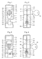
- Fig. 1 einen Seitenriss der Vorrichtung in Offenstellung,
- Fig. 2 eine Ansicht von der Rückseite der Vorrichtung in Offenstellung,
- Fig. 3 einen Seitenriss wie in Fig. 1, aber in Sicherungslage und mit andeutungsweise dargestelltem Bügel
- Fig. 4 eine Ansicht von der Rückseite wie in Fig. 2, aber in Sicherungslage
- Fig. 5 ein perspektivisches Bild der Teile in auseinandergezogener Darstellung.
- 1 is a side elevation of the device in the open position,
- 2 is a view from the rear of the device in the open position,
- Fig. 3 is a side elevation as in Fig. 1, but in the secured position and with a hint shown
- Fig. 4 is a view from the rear as in Fig. 2, but in the secured position
- Fig. 5 is an exploded perspective view of the parts.
Eine prismatische Hülse 1 mit beispielsweise quadratischer Grundfläche hat in ihrer unteren Partie eine Ausnehmung 10, die sich quer über die ganze Vorderwand 3 und teilweise über beide Seitenwände 2,4 erstreckt. Nahe bei den beiden Kanten zwischen Vorderwand 3 und den Seitenwänden 2,4 sind an den Seitenwänden 2,4 je eine gerade, in die Ausnehmung 10 hineinragende Lasche 11 vorhanden, an denen von rechts oder von links ein Bügel 12 angehängt, oder, wenn er eine Bohrung 13 besitzt, eingehängt werden kann, wie dies in Fig. 3 angedeutet ist.A
In der Vorderwand 3 und in der Rückwand 5 sind je eine Bohrung 31 bzw. 51 vorhanden, durch die eine Schraube (nicht dargestellt) hindurchgesteckt und damit die Hülse 1 am Fenster-, Tür- oder Flügelrahmen angeschraubt werden kann. Im Bereich der Ausnehmung 10 weist die Rückwand 5 eine zweite Bohrung 52 auf, um die Hülse 1 an einer zweiten Stelle zu befestigen, wie Fig. 2,4 und 5 zeigen.In the
In die Hülse 1 ist ein axial verschiebbarer Verschlussblock 6 eingesetzt. Dieser besteht aus einem Sicherungsteil 61 und einem Hauptteil 62. In eine Durchgangsbohrung 67 im Hauptteil 62 ist eine Hülse 63 mit einem axial verschiebbaren Schliesszylinder 64 eingelegt. Der Schliesszylinder 64 rastet bei axialer Verschiebung in der Hülse 63 ein und kann mit einem Schlüssel 65 aus der Rast gelöst werden. An der dem Schlüsselloch abgewandten Seite ist der Schliesszylinder 64 mit einem Zapfen 66 versehen, der in der Sicherungslage in eine Ausnehmung 21 in der Seitenwand 2 eingreift und damit den Verschlussblock 6 in Sicherungslage hält.An axially
Im Hauptteil 62 ist senkrecht zur genannten Durchgangsbohrung 67 noch eine zweite Durchgangsbohrung 68 vorhanden, die zur Verbindung der beiden Bohrungen 31,51 zum Einsetzen einer Schraube dient. Die Bohrung 51 ist nur in einer Zwischenstellung des Verschlussblockes 6 zugänglich und in der Sicherungslage verdeckt. Gleicherweise verdeckt der Sicherungsteil 61 in der Sicherungslage die Bohrung 52, so dass die Schraubenköpfe in Sicherungslage nicht zugänglich sind.In the
In der einen Seitenwand 4 ist eine knopflochartige Ausnehmung 41 vorhanden, die zur Führung des Schliesszylinders 64 und im erweiterten Teil zu dessen Ein- und Ausbau dient.In one
Der Verschlussblock 6 ist mit einer Längsnut 69 versehen, die zur Führung einer Rückstell-Druckfeder 7 dient. Diese ist einerseits an Laschen 53 an der Rückwand und anderseits an einem Absatz 70 im Verschlussblock 6 abgestützt und presst den Verschlussblock 6 in seine Ruhelage bzw. in die Offenstellung bezüglich der Laschen 11. Der Absatz 71 und eine zweite axiale Nut 72 auf der gegenüberliegenden Seite bezüglich des Absatzes 71 dienen zum Einsetzen eines Deckels, der mit einem Zapfen 73 an einer Lasche 74 in die Bohrung 31 der Seitenwand 3 eingreift und nur in Sicherungslage des Verschlussblockes 6 entfernt werden kann.The
Wenn der Zapfen 66 des Schliesszylinders 64 auch in der Offenstellung in eine Bohrung einrastbar wäre, so dass der Schlüssel 65 nicht nur zum Oeffnen, sondern auch zum Schliessen benützt werden müsste, gäbe es für einen Einbrecher keine Chance, in irgend einer Lage des Verschlussblockes 6 eine Manipulation vorzunehmen, um die Sicherungsvorrichtung unwirksam zu machen. Durch den Absatz 71 und die Längsnut 69 kann ein Schraubenkopf zur Befestigung der Hülse 1 die Funktion zudem nicht behindern.If the
Claims (3)
Priority Applications (1)
| Application Number | Priority Date | Filing Date | Title |
|---|---|---|---|
| AT88810382T ATE70880T1 (en) | 1987-07-20 | 1988-06-09 | SAFETY DEVICE FOR SECURING CLOSED BLINDS. |
Applications Claiming Priority (2)
| Application Number | Priority Date | Filing Date | Title |
|---|---|---|---|
| CH2737/87A CH674876A5 (en) | 1987-07-20 | 1987-07-20 | |
| CH2737/87 | 1987-07-20 |
Publications (3)
| Publication Number | Publication Date |
|---|---|
| EP0302005A2 true EP0302005A2 (en) | 1989-02-01 |
| EP0302005A3 EP0302005A3 (en) | 1989-06-14 |
| EP0302005B1 EP0302005B1 (en) | 1991-12-27 |
Family
ID=4240481
Family Applications (1)
| Application Number | Title | Priority Date | Filing Date |
|---|---|---|---|
| EP88810382A Expired - Lifetime EP0302005B1 (en) | 1987-07-20 | 1988-06-09 | Lock for venetian blind |
Country Status (4)
| Country | Link |
|---|---|
| EP (1) | EP0302005B1 (en) |
| AT (1) | ATE70880T1 (en) |
| CH (1) | CH674876A5 (en) |
| DE (1) | DE3867167D1 (en) |
Cited By (6)
| Publication number | Priority date | Publication date | Assignee | Title |
|---|---|---|---|---|
| DE4112357A1 (en) * | 1991-04-16 | 1992-10-22 | Helmut Muecke | Locking device for rubbish bins - has attachment with bore for bolt and lock to hold lid closed |
| DE29619910U1 (en) * | 1996-11-18 | 1997-01-23 | Paliakoudis, Joannis, 73734 Esslingen | Device for receiving information or advertising media |
| WO1999062381A1 (en) * | 1998-06-03 | 1999-12-09 | Valeo Jean Michel | Protection device for fixing a painting or the like on a wall |
| NL1013185C2 (en) * | 1999-09-30 | 2001-04-03 | Andreas Paulus Maria Van Beers | Lock assembly. |
| WO2012036080A1 (en) | 2010-09-16 | 2012-03-22 | Yamada Yasuyuki | Bitterness-masking ingredient and bitterness-masking method |
| DE102015118260B4 (en) | 2015-10-27 | 2022-11-24 | Aco Ahlmann Se & Co. Kg | Closing device for a cover, lockable cover system |
Family Cites Families (3)
| Publication number | Priority date | Publication date | Assignee | Title |
|---|---|---|---|---|
| US2734373A (en) * | 1956-02-14 | scherbinski | ||
| FR2566824A1 (en) * | 1984-06-27 | 1986-01-03 | Peratout Maurice | Anti-theft device for sailboards and their accessories |
| FR2588407A1 (en) * | 1985-10-04 | 1987-04-10 | Granada France Sa | Safety fixing system for equipment support panel, particularly for television sets |
-
1987
- 1987-07-20 CH CH2737/87A patent/CH674876A5/de not_active IP Right Cessation
-
1988
- 1988-06-09 EP EP88810382A patent/EP0302005B1/en not_active Expired - Lifetime
- 1988-06-09 DE DE8888810382T patent/DE3867167D1/en not_active Expired - Fee Related
- 1988-06-09 AT AT88810382T patent/ATE70880T1/en active
Cited By (8)
| Publication number | Priority date | Publication date | Assignee | Title |
|---|---|---|---|---|
| DE4112357A1 (en) * | 1991-04-16 | 1992-10-22 | Helmut Muecke | Locking device for rubbish bins - has attachment with bore for bolt and lock to hold lid closed |
| DE29619910U1 (en) * | 1996-11-18 | 1997-01-23 | Paliakoudis, Joannis, 73734 Esslingen | Device for receiving information or advertising media |
| WO1999062381A1 (en) * | 1998-06-03 | 1999-12-09 | Valeo Jean Michel | Protection device for fixing a painting or the like on a wall |
| FR2779470A1 (en) * | 1998-06-03 | 1999-12-10 | Jean Michel Valeo | PROTECTION DEVICE FOR FIXING A PANEL OR THE LIKE ON A WALL |
| NL1013185C2 (en) * | 1999-09-30 | 2001-04-03 | Andreas Paulus Maria Van Beers | Lock assembly. |
| EP1088956A1 (en) * | 1999-09-30 | 2001-04-04 | van Beers, Andreas Paulus Maria | Lock assembly |
| WO2012036080A1 (en) | 2010-09-16 | 2012-03-22 | Yamada Yasuyuki | Bitterness-masking ingredient and bitterness-masking method |
| DE102015118260B4 (en) | 2015-10-27 | 2022-11-24 | Aco Ahlmann Se & Co. Kg | Closing device for a cover, lockable cover system |
Also Published As
| Publication number | Publication date |
|---|---|
| DE3867167D1 (en) | 1992-02-06 |
| EP0302005B1 (en) | 1991-12-27 |
| ATE70880T1 (en) | 1992-01-15 |
| CH674876A5 (en) | 1990-07-31 |
| EP0302005A3 (en) | 1989-06-14 |
Similar Documents
| Publication | Publication Date | Title |
|---|---|---|
| DE69200090T2 (en) | Building a security door. | |
| EP0302005B1 (en) | Lock for venetian blind | |
| DE69511299T2 (en) | security system | |
| DE10310403A1 (en) | closing bar | |
| DE4227448C2 (en) | Lock security for security lock cylinders | |
| DE3614031A1 (en) | Door chain | |
| DE60007357T2 (en) | Burglar alarm system for door leaves | |
| DE102012020025A1 (en) | Burglary prevention device for e.g. terrace door in private residential building, has removable safety bar extended in general vertical direction over window- or door opening after fastening at mounting plates | |
| DE3308319C2 (en) | ||
| DE3314753A1 (en) | MULTI-PIECE HINGE | |
| DE19507481C1 (en) | Lockable window hasp with front body fixed to casement main body | |
| DE2930393A1 (en) | MULTI-CHAMBER IONIZATION DETECTOR | |
| DE3030393A1 (en) | Drill resistant mortice door lock - has bottom blocking plate and rear angular plate protecting tumbler plate | |
| EP0244564B1 (en) | Protecting device against drilling of a lock | |
| CH643911A5 (en) | A break-in rosette on a mortise lock. | |
| AT397120B (en) | Additional door securing device, holder for a key for use with this additional door securing device and a door securing system | |
| DE102017009348B4 (en) | Window & door security for subsequent security for at least one wing, window or door | |
| DE3151982C2 (en) | ||
| EP1130200B1 (en) | Locking device | |
| DE29805276U1 (en) | Device with a burglar alarm to close an opening | |
| DE29513923U1 (en) | Device for securing windows, doors and the like | |
| DE2755961A1 (en) | Intruder resistant lock with sheath bar holder - has retaining screws through plate into integral holes set back from rail | |
| DE4019952C2 (en) | Safety device on doors | |
| DE9206160U1 (en) | Security device for windows and doors | |
| DE19932406A1 (en) | Door case with hinges and break-in preventer uses sloping recess on case face so door closes onto this recess face to hold door in despite hinge removal. |
Legal Events
| Date | Code | Title | Description |
|---|---|---|---|
| PUAI | Public reference made under article 153(3) epc to a published international application that has entered the european phase |
Free format text: ORIGINAL CODE: 0009012 |
|
| AK | Designated contracting states |
Kind code of ref document: A2 Designated state(s): AT BE CH DE ES FR GB GR IT LI LU NL SE |
|
| PUAL | Search report despatched |
Free format text: ORIGINAL CODE: 0009013 |
|
| AK | Designated contracting states |
Kind code of ref document: A3 Designated state(s): AT BE CH DE ES FR GB GR IT LI LU NL SE |
|
| 17P | Request for examination filed |
Effective date: 19890629 |
|
| 17Q | First examination report despatched |
Effective date: 19910227 |
|
| GRAA | (expected) grant |
Free format text: ORIGINAL CODE: 0009210 |
|
| AK | Designated contracting states |
Kind code of ref document: B1 Designated state(s): AT BE CH DE ES FR GB GR IT LI LU NL SE |
|
| PG25 | Lapsed in a contracting state [announced via postgrant information from national office to epo] |
Ref country code: IT Free format text: LAPSE BECAUSE OF FAILURE TO SUBMIT A TRANSLATION OF THE DESCRIPTION OR TO PAY THE FEE WITHIN THE PRE;WARNING: LAPSES OF ITALIAN PATENTS WITH EFFECTIVE DATE BEFORE 2007 MAY HAVE OCCURRED AT ANY TIME BEFORE 2007. THE CORRECT EFFECTIVE DATE MAY BE DIFFERENT FROM THE ONE RECORDED.SCRIBED TIME-LIMIT Effective date: 19911227 Ref country code: NL Effective date: 19911227 Ref country code: SE Effective date: 19911227 Ref country code: GR Free format text: LAPSE BECAUSE OF FAILURE TO SUBMIT A TRANSLATION OF THE DESCRIPTION OR TO PAY THE FEE WITHIN THE PRESCRIBED TIME-LIMIT Effective date: 19911227 Ref country code: BE Effective date: 19911227 Ref country code: ES Free format text: THE PATENT HAS BEEN ANNULLED BY A DECISION OF A NATIONAL AUTHORITY Effective date: 19911227 Ref country code: GB Effective date: 19911227 |
|
| REF | Corresponds to: |
Ref document number: 70880 Country of ref document: AT Date of ref document: 19920115 Kind code of ref document: T |
|
| ET | Fr: translation filed | ||
| REF | Corresponds to: |
Ref document number: 3867167 Country of ref document: DE Date of ref document: 19920206 |
|
| NLV1 | Nl: lapsed or annulled due to failure to fulfill the requirements of art. 29p and 29m of the patents act | ||
| PG25 | Lapsed in a contracting state [announced via postgrant information from national office to epo] |
Ref country code: LU Free format text: LAPSE BECAUSE OF NON-PAYMENT OF DUE FEES Effective date: 19920630 |
|
| GBV | Gb: ep patent (uk) treated as always having been void in accordance with gb section 77(7)/1977 [no translation filed] | ||
| ITF | It: translation for a ep patent filed | ||
| PLBE | No opposition filed within time limit |
Free format text: ORIGINAL CODE: 0009261 |
|
| STAA | Information on the status of an ep patent application or granted ep patent |
Free format text: STATUS: NO OPPOSITION FILED WITHIN TIME LIMIT |
|
| 26N | No opposition filed | ||
| PGFP | Annual fee paid to national office [announced via postgrant information from national office to epo] |
Ref country code: FR Payment date: 19930512 Year of fee payment: 6 |
|
| PGFP | Annual fee paid to national office [announced via postgrant information from national office to epo] |
Ref country code: AT Payment date: 19930513 Year of fee payment: 6 |
|
| PGFP | Annual fee paid to national office [announced via postgrant information from national office to epo] |
Ref country code: DE Payment date: 19930524 Year of fee payment: 6 |
|
| PGFP | Annual fee paid to national office [announced via postgrant information from national office to epo] |
Ref country code: CH Payment date: 19930702 Year of fee payment: 6 |
|
| PG25 | Lapsed in a contracting state [announced via postgrant information from national office to epo] |
Ref country code: AT Effective date: 19940609 |
|
| PG25 | Lapsed in a contracting state [announced via postgrant information from national office to epo] |
Ref country code: LI Effective date: 19940630 Ref country code: CH Effective date: 19940630 |
|
| PG25 | Lapsed in a contracting state [announced via postgrant information from national office to epo] |
Ref country code: FR Effective date: 19950228 |
|
| REG | Reference to a national code |
Ref country code: CH Ref legal event code: PL |
|
| PG25 | Lapsed in a contracting state [announced via postgrant information from national office to epo] |
Ref country code: DE Effective date: 19950301 |
|
| REG | Reference to a national code |
Ref country code: FR Ref legal event code: ST |