EP0302136B1 - Outil de rivetage - Google Patents
Outil de rivetage Download PDFInfo
- Publication number
- EP0302136B1 EP0302136B1 EP19870111438 EP87111438A EP0302136B1 EP 0302136 B1 EP0302136 B1 EP 0302136B1 EP 19870111438 EP19870111438 EP 19870111438 EP 87111438 A EP87111438 A EP 87111438A EP 0302136 B1 EP0302136 B1 EP 0302136B1
- Authority
- EP
- European Patent Office
- Prior art keywords
- valve
- piston
- pressure
- tappet
- trigger
- Prior art date
- Legal status (The legal status is an assumption and is not a legal conclusion. Google has not performed a legal analysis and makes no representation as to the accuracy of the status listed.)
- Expired - Lifetime
Links
Images
Classifications
-
- B—PERFORMING OPERATIONS; TRANSPORTING
- B25—HAND TOOLS; PORTABLE POWER-DRIVEN TOOLS; MANIPULATORS
- B25B—TOOLS OR BENCH DEVICES NOT OTHERWISE PROVIDED FOR, FOR FASTENING, CONNECTING, DISENGAGING, OR HOLDING
- B25B27/00—Hand tools, specially adapted for fitting together or separating parts or objects whether or not involving some deformation, not otherwise provided for
- B25B27/0007—Tools for fixing internally screw-threaded tubular fasteners
- B25B27/0014—Tools for fixing internally screw-threaded tubular fasteners motor-driven
-
- B—PERFORMING OPERATIONS; TRANSPORTING
- B21—MECHANICAL METAL-WORKING WITHOUT ESSENTIALLY REMOVING MATERIAL; PUNCHING METAL
- B21J—FORGING; HAMMERING; PRESSING METAL; RIVETING; FORGE FURNACES
- B21J15/00—Riveting
- B21J15/10—Riveting machines
- B21J15/105—Portable riveters
Definitions
- the invention relates to a rivet setting tool for setting threaded rivet nuts or blind rivet nuts with a feed device which can be actuated for the upsetting process and which gives the threaded bolt or draw bolt an axial movement and which has a cylinder-piston arrangement consisting of a pressure piston and a working piston, and with a pusher, who moves a control valve rod by exerting pressure, which opens or closes connection openings for a pressure medium for actuating the tool, the pusher being movable in a plane oblique to the axis of a control valve rod and moving it downward (see, for example, DE-A 3 603 421).
- the pressure piston of the feed device is pneumatically actuated by a corresponding assignment of valve openings and compressed air is conveyed into the device for sucking in a blind rivet and for removing torn rivet pins.
- the valve rod extends from the pusher arranged below the head on the device to the base of the device, in which the pneumatically actuated pressure piston sits and into which the compressed air line opens. Relatively large forces must therefore be applied by the pusher to actuate the valve rod, which makes it difficult to actuate the device.
- the invention is therefore based on the object of making available a rivet setting tool of the type mentioned, in which the actuation is facilitated.
- the invention consists in that the valve rod ends in a valve piston seated in a cylinder chamber and that the pusher acts on a valve tappet which opens a pressure medium passage from a pressure chamber provided in the valve piston to the cylinder chamber.
- An advantageous embodiment consists in that the pressure medium passage consists of an annular space which is formed in that the valve tappet has a smaller diameter than the valve tappet bore which leads to the cylinder chamber, and in that the cylinder chamber is formed between the end face of the valve piston and the cylinder end wall, through which the valve lifter is passed in a sealed manner.
- the pressure chamber provided in the valve piston expediently consists of a compressed air bore connected to the pressure medium supply and passing through the valve rod in the center.
- a helical spring arranged in the compressed air bore urges the valve body, which is attached to the end of the valve tappet, into the closed position.
- valve piston be seated on the valve rod and communicate this to its movement.
- the pusher expediently has an actuating bolt which acts on the valve tappet.
- the actuating bolt can carry a cone at its end, which is in contact with the rounded valve stem.
- a vent hole in the cylinder chamber is open in the rest position of the pusher.
- the invention proposes that the valve tappet and the actuating pin release a ventilation channel from the cylinder chamber between themselves and the guide surfaces and that a seal closes the ventilation passage when the pusher is actuated.
- An expedient measure is that the pusher cover, to which the actuating bolt is fastened, closes a venting passage between itself and a guide body in the actuating position.
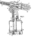
- a rivet setting tool 1 which consists of a device part 2 and a handle part 3.
- a working piston 4 with a working piston rod 5, which acts on the mouthpiece 6 at the front end of the device part 2 in order to carry out the operations with the rivets 7.
- a pneumatically actuated pressure piston 8 is seated in the grip part 3 and is seated in a pressure chamber 9.
- a control valve rod 10 which is equipped at its lower end 11 with valve seats and has a valve rod channel 12 which can be aligned at its upper end with a bore 13 in the handle part.
- a valve rod channel 12 which can be aligned at its upper end with a bore 13 in the handle part.
- a pusher 15 is arranged obliquely to the axis of the control valve rod 10 and obliquely, i. H. at an angle to the axis of the control valve rod 10, movable.
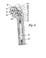
- valve rod 10 runs out at its upper end in a valve piston 18 which is seated in a cylinder chamber 19.
- the pusher 15 acts on a valve lifter 17 which is seated in a pressure medium passage 22.
- This pressure medium passage 22 is formed in that the outer diameter of the valve lifter 17 has a smaller diameter than the valve lifter bore in the valve piston 18.
- a valve body arranged by 23 which opens the pressure medium passage 22 after moving downward in FIG. 2.
- a connection is established between the pressure medium passage 22 and the pressure chamber 24, which is connected to the valve rod channel 12, which is filled with compressed air.
- This passes through the pressure medium passage 22 into the cylinder chamber 19 and moves the valve piston 18 and thus the valve rod 10 downward, which in turn moves the pressure piston upward through the compressed air flowing into the pressure chamber 9 and actuates the working piston in the device part 2.
- valve tappet If the pusher 15 is relieved, the valve tappet returns to its starting position due to a helical spring 25 located in the pressure chamber 24. Characterized the pressure medium passage 22 is closed by the valve body 23.
- the air in the control chamber 19 passes through a passage 26 into a housing recess 27 in which the pusher 15 is seated with a guide body 28.
- Extending through a central bore 29 in the guide body 28 is an actuating bolt 30 extending from the pusher 15, which carries at its lower end a cone 31 which is in contact with the rounded end 16 of the valve lifter 17.
- the pusher 15 moves an annular seal 32 arranged thereon from its seat 33 in the guide body 28, and the compressed air can escape from the housing bore 27 through the central bore 29 in the guide body 28 to the outside. This also relieves the pressure on the cylinder chamber 19, and the compression spring 14 presses the valve rod 10 with the valve piston 18 upwards again into the starting position.
Landscapes
- Engineering & Computer Science (AREA)
- Mechanical Engineering (AREA)
- Portable Nailing Machines And Staplers (AREA)
Claims (10)
Priority Applications (2)
| Application Number | Priority Date | Filing Date | Title |
|---|---|---|---|
| DE8787111438T DE3766497D1 (de) | 1987-08-07 | 1987-08-07 | Nietsetzwerkzeug. |
| EP19870111438 EP0302136B1 (fr) | 1987-08-07 | 1987-08-07 | Outil de rivetage |
Applications Claiming Priority (1)
| Application Number | Priority Date | Filing Date | Title |
|---|---|---|---|
| EP19870111438 EP0302136B1 (fr) | 1987-08-07 | 1987-08-07 | Outil de rivetage |
Publications (2)
| Publication Number | Publication Date |
|---|---|
| EP0302136A1 EP0302136A1 (fr) | 1989-02-08 |
| EP0302136B1 true EP0302136B1 (fr) | 1990-11-28 |
Family
ID=8197192
Family Applications (1)
| Application Number | Title | Priority Date | Filing Date |
|---|---|---|---|
| EP19870111438 Expired - Lifetime EP0302136B1 (fr) | 1987-08-07 | 1987-08-07 | Outil de rivetage |
Country Status (2)
| Country | Link |
|---|---|
| EP (1) | EP0302136B1 (fr) |
| DE (1) | DE3766497D1 (fr) |
Cited By (1)
| Publication number | Priority date | Publication date | Assignee | Title |
|---|---|---|---|---|
| US11673243B2 (en) | 2018-09-05 | 2023-06-13 | Milwaukee Electric Tool Corporation | Blind rivet nut-setting tool |
Families Citing this family (5)
| Publication number | Priority date | Publication date | Assignee | Title |
|---|---|---|---|---|
| IT1235969B (it) * | 1989-11-17 | 1992-12-15 | Far Snc Di Generali Giacomo & | Dispositivo per il recupero della pressione fluidodinamica in particolare per macchine rivettatrici |
| GB2301547A (en) * | 1995-06-02 | 1996-12-11 | Avdel Systems Ltd | Fastener installation tool |
| GB2500897B (en) * | 2012-04-03 | 2014-08-27 | Infastech Ip Pte Ltd | Fastener installation tool |
| CN108746456B (zh) * | 2018-08-29 | 2024-06-21 | 姚永法 | 一种快捷式拉铆枪 |
| US12453999B2 (en) | 2021-07-28 | 2025-10-28 | Milwaukee Electric Tool Corporation | Blind rivet nut-setting tool |
Family Cites Families (8)
| Publication number | Priority date | Publication date | Assignee | Title |
|---|---|---|---|---|
| GB542048A (en) * | 1939-10-19 | 1941-12-23 | Chicago Pneumatic Tool Co | Single action pneumatic riveter and like percussive tools |
| GB1479375A (en) * | 1974-05-25 | 1977-07-13 | Gesipa Blindentechnik Gmbh | Pneumatic-mechanical blind riveting tool |
| SE428537B (sv) * | 1979-01-15 | 1983-07-11 | Lars Erik Gunnar Olsson | Pneumatiskt-hydrauliskt verktyg, foretredesvis for blindnitning |
| DE2902358A1 (de) * | 1979-01-22 | 1980-07-31 | Schwab Fa Manfred | Ventilbetaetigungseinrichtung fuer ein pneumatisches handgeraet |
| DE3125838A1 (de) * | 1981-07-01 | 1983-01-27 | Manfred 6200 Wiesbaden Schwab | Blindnietgeraet mit nietstiftfoerderung |
| DE3330891A1 (de) * | 1983-08-26 | 1985-03-14 | Vsesojuznyj naučno-issledovatel'skij i proektno-konstruktorskij institut mechanizirovannogo i ručnogo stroitel'no-montažnogo instrumenta, vibratorov i stroitel'no-otdeločnych mašin VNNISMI, Chimki, Moskovskaja oblast' | Handgriff einer druckluftmaschine |
| DE3664579D1 (en) * | 1985-05-10 | 1989-08-31 | Avdel Systems Ltd | Breakstem fastener installation tool |
| DE3603421A1 (de) * | 1986-02-05 | 1987-08-06 | Schwab Maschbau | Betaetigungseinrichtung fuer nietsetzwerkzeug |
-
1987
- 1987-08-07 EP EP19870111438 patent/EP0302136B1/fr not_active Expired - Lifetime
- 1987-08-07 DE DE8787111438T patent/DE3766497D1/de not_active Expired - Fee Related
Cited By (1)
| Publication number | Priority date | Publication date | Assignee | Title |
|---|---|---|---|---|
| US11673243B2 (en) | 2018-09-05 | 2023-06-13 | Milwaukee Electric Tool Corporation | Blind rivet nut-setting tool |
Also Published As
| Publication number | Publication date |
|---|---|
| DE3766497D1 (de) | 1991-01-10 |
| EP0302136A1 (fr) | 1989-02-08 |
Similar Documents
| Publication | Publication Date | Title |
|---|---|---|
| EP0236464B1 (fr) | Outil a river | |
| DE1503076C3 (de) | Steuereinrichtung an einem Druckluftnagler zum Steuern von einzelnen oder fortlaufenden Arbeitsspielen | |
| EP0302128B1 (fr) | Outil de pose de rivets pour poser des rivets borgnes | |
| DE3014803C2 (de) | Druckluftnagler | |
| DE4324163C2 (de) | Kontinuierlich arbeitende Nietmaschine zum Befestigen von Blindnieten | |
| EP3446833B1 (fr) | Cloueur à air comprimé pourvu de dispositif de soupape de sécurité | |
| DE69720847T2 (de) | Eintreibgerät für Befestigungsmittel mit einem Ventil für ganzen Zyklen | |
| DE2603784A1 (de) | Sicherheitslufteinlass-ventilsteuerung fuer ein druckluftbetriebenes handwerkzeug | |
| DE69607564T2 (de) | Eintreibgerät für Befestigungsmittel mit Hauptventil/Gehäuse-Ventilanordnung | |
| DE69703360T2 (de) | Eintreibgerät für befestigungsmittel mit verbessertem betätigungsmechanismus | |
| EP0302136B1 (fr) | Outil de rivetage | |
| DE69806627T2 (de) | Eintreibgerät für befestigungselemente mit auswechselbaren steuermodulen | |
| DE2800970C2 (de) | Nietpistole für das Setzen von Blind-Hohlnieten | |
| DE2718942C3 (de) | Auslösesicherung an einem Druckluftnagler | |
| EP0259405B1 (fr) | Dispositif d'actionnement pour outil de rivetage | |
| DE4032231C2 (fr) | ||
| DE3701883C2 (de) | Blindnietsetzwerkzeug | |
| DE2607263A1 (de) | Druckluft-blindnietwerkzeug | |
| EP3257632A1 (fr) | Cloueur a air comprime comprenant un declenchement sequentiel et par contact | |
| DE2810285A1 (de) | Schlagwerkzeug | |
| DE2613565A1 (de) | Fluidbetaetigtes befestigungswerkzeug | |
| DE2419190C3 (de) | Pneumatisch-hydraulisches Blindnietgerät | |
| DE3506950C2 (de) | Werkzeug zum Setzen von zweiteiligen Befestigern | |
| DE3153057C2 (de) | Pneumatisch-hydraulisches Blindnietgerät | |
| DE2223999C2 (de) | Einlaß- und Auslaßventilanordnung für den Arbeitshubraum eines Druckluftnaglers |
Legal Events
| Date | Code | Title | Description |
|---|---|---|---|
| PUAI | Public reference made under article 153(3) epc to a published international application that has entered the european phase |
Free format text: ORIGINAL CODE: 0009012 |
|
| AK | Designated contracting states |
Kind code of ref document: A1 Designated state(s): DE FR GB IT SE |
|
| 17P | Request for examination filed |
Effective date: 19890802 |
|
| 17Q | First examination report despatched |
Effective date: 19900504 |
|
| ITF | It: translation for a ep patent filed | ||
| GRAA | (expected) grant |
Free format text: ORIGINAL CODE: 0009210 |
|
| AK | Designated contracting states |
Kind code of ref document: B1 Designated state(s): DE FR GB IT SE |
|
| GBT | Gb: translation of ep patent filed (gb section 77(6)(a)/1977) | ||
| REF | Corresponds to: |
Ref document number: 3766497 Country of ref document: DE Date of ref document: 19910110 |
|
| ET | Fr: translation filed | ||
| RAP2 | Party data changed (patent owner data changed or rights of a patent transferred) |
Owner name: MASCHINENBAU SUBOTSCH & SCHWAB GMBH |
|
| ITTA | It: last paid annual fee | ||
| PLBE | No opposition filed within time limit |
Free format text: ORIGINAL CODE: 0009261 |
|
| STAA | Information on the status of an ep patent application or granted ep patent |
Free format text: STATUS: NO OPPOSITION FILED WITHIN TIME LIMIT |
|
| 26N | No opposition filed | ||
| REG | Reference to a national code |
Ref country code: FR Ref legal event code: TP |
|
| EAL | Se: european patent in force in sweden |
Ref document number: 87111438.5 |
|
| REG | Reference to a national code |
Ref country code: FR Ref legal event code: TP |
|
| REG | Reference to a national code |
Ref country code: GB Ref legal event code: IF02 |
|
| PGFP | Annual fee paid to national office [announced via postgrant information from national office to epo] |
Ref country code: GB Payment date: 20040726 Year of fee payment: 18 |
|
| PGFP | Annual fee paid to national office [announced via postgrant information from national office to epo] |
Ref country code: FR Payment date: 20040820 Year of fee payment: 18 |
|
| PGFP | Annual fee paid to national office [announced via postgrant information from national office to epo] |
Ref country code: SE Payment date: 20040823 Year of fee payment: 18 |
|
| PGFP | Annual fee paid to national office [announced via postgrant information from national office to epo] |
Ref country code: DE Payment date: 20040913 Year of fee payment: 18 |
|
| PG25 | Lapsed in a contracting state [announced via postgrant information from national office to epo] |
Ref country code: IT Free format text: LAPSE BECAUSE OF NON-PAYMENT OF DUE FEES;WARNING: LAPSES OF ITALIAN PATENTS WITH EFFECTIVE DATE BEFORE 2007 MAY HAVE OCCURRED AT ANY TIME BEFORE 2007. THE CORRECT EFFECTIVE DATE MAY BE DIFFERENT FROM THE ONE RECORDED. Effective date: 20050807 Ref country code: GB Free format text: LAPSE BECAUSE OF NON-PAYMENT OF DUE FEES Effective date: 20050807 |
|
| PG25 | Lapsed in a contracting state [announced via postgrant information from national office to epo] |
Ref country code: SE Free format text: LAPSE BECAUSE OF NON-PAYMENT OF DUE FEES Effective date: 20050808 |
|
| PG25 | Lapsed in a contracting state [announced via postgrant information from national office to epo] |
Ref country code: DE Free format text: LAPSE BECAUSE OF NON-PAYMENT OF DUE FEES Effective date: 20060301 |
|
| EUG | Se: european patent has lapsed | ||
| GBPC | Gb: european patent ceased through non-payment of renewal fee |
Effective date: 20050807 |
|
| PG25 | Lapsed in a contracting state [announced via postgrant information from national office to epo] |
Ref country code: FR Free format text: LAPSE BECAUSE OF NON-PAYMENT OF DUE FEES Effective date: 20060428 |
|
| REG | Reference to a national code |
Ref country code: FR Ref legal event code: ST Effective date: 20060428 |