EP0302187A1 - Dispositif de serrage sur tours avec mandrin - Google Patents
Dispositif de serrage sur tours avec mandrin Download PDFInfo
- Publication number
- EP0302187A1 EP0302187A1 EP88107289A EP88107289A EP0302187A1 EP 0302187 A1 EP0302187 A1 EP 0302187A1 EP 88107289 A EP88107289 A EP 88107289A EP 88107289 A EP88107289 A EP 88107289A EP 0302187 A1 EP0302187 A1 EP 0302187A1
- Authority
- EP
- European Patent Office
- Prior art keywords
- control
- piston
- chuck
- chuck body
- clamping
- Prior art date
- Legal status (The legal status is an assumption and is not a legal conclusion. Google has not performed a legal analysis and makes no representation as to the accuracy of the status listed.)
- Granted
Links
- 238000006073 displacement reaction Methods 0.000 claims abstract description 14
- 230000004323 axial length Effects 0.000 claims description 3
- 230000000903 blocking effect Effects 0.000 abstract description 7
- 238000000034 method Methods 0.000 description 3
- 230000001771 impaired effect Effects 0.000 description 1
- 230000001939 inductive effect Effects 0.000 description 1
- 238000003754 machining Methods 0.000 description 1
- 238000012544 monitoring process Methods 0.000 description 1
Images

Classifications
-
- B—PERFORMING OPERATIONS; TRANSPORTING
- B23—MACHINE TOOLS; METAL-WORKING NOT OTHERWISE PROVIDED FOR
- B23B—TURNING; BORING
- B23B31/00—Chucks; Expansion mandrels; Adaptations thereof for remote control
- B23B31/02—Chucks
- B23B31/10—Chucks characterised by the retaining or gripping devices or their immediate operating means
- B23B31/12—Chucks with simultaneously-acting jaws, whether or not also individually adjustable
- B23B31/16—Chucks with simultaneously-acting jaws, whether or not also individually adjustable moving radially
- B23B31/16233—Jaws movement actuated by oblique surfaces of a coaxial control rod
- B23B31/16254—Jaws movement actuated by oblique surfaces of a coaxial control rod using fluid-pressure means to actuate the gripping means
-
- Y—GENERAL TAGGING OF NEW TECHNOLOGICAL DEVELOPMENTS; GENERAL TAGGING OF CROSS-SECTIONAL TECHNOLOGIES SPANNING OVER SEVERAL SECTIONS OF THE IPC; TECHNICAL SUBJECTS COVERED BY FORMER USPC CROSS-REFERENCE ART COLLECTIONS [XRACs] AND DIGESTS
- Y10—TECHNICAL SUBJECTS COVERED BY FORMER USPC
- Y10T—TECHNICAL SUBJECTS COVERED BY FORMER US CLASSIFICATION
- Y10T279/00—Chucks or sockets
- Y10T279/12—Chucks or sockets with fluid-pressure actuator
- Y10T279/1208—Chucks or sockets with fluid-pressure actuator with measuring, indicating or control means
-
- Y—GENERAL TAGGING OF NEW TECHNOLOGICAL DEVELOPMENTS; GENERAL TAGGING OF CROSS-SECTIONAL TECHNOLOGIES SPANNING OVER SEVERAL SECTIONS OF THE IPC; TECHNICAL SUBJECTS COVERED BY FORMER USPC CROSS-REFERENCE ART COLLECTIONS [XRACs] AND DIGESTS
- Y10—TECHNICAL SUBJECTS COVERED BY FORMER USPC
- Y10T—TECHNICAL SUBJECTS COVERED BY FORMER US CLASSIFICATION
- Y10T279/00—Chucks or sockets
- Y10T279/19—Radially reciprocating jaws
- Y10T279/1906—Radially reciprocating jaws with indicator
Definitions
- the invention relates to a clamping device on lathes with a chuck, in the chuck body of which jaws are guided, for the adjustment of which an axially adjustable drive member is provided, the function of which is monitored by a function control device acting on the rotary drive of the machine and for the adjustment along an axial Stroke is designed as a tensioning piston which can be acted upon by a pressure medium or is connected to such a tensioning piston, the function control device comprising a sensor which is fixed outside the chuck, a switching element which actuates the sensor and is arranged on the outer circumference of the chuck body, and a control piston which adjusts the switching element and acts against the force a return spring is acted upon by the pressure medium of the tensioning piston and is locked by the drive element against displacements caused by the pressure medium in a blocking position that switches off the rotary drive b is lockable when the drive member is outside a working range of its axial stroke.
- Such tensioning devices are known from DE-OS 31 02 099.
- the function control device enables a control of both the clamping path and the clamping force, even when the chuck is running, so that the turning process is only possible if the for the secure clamping of the Required displacement of the drive member in the chuck took place and the clamping pressure on the clamping piston has built up to a sufficient level.
- the control piston is guided radially in the chuck body and has a locking lug for locking it on its radially inner end, which locking lugs on the drive member are assigned to it.
- This arrangement of the control piston in conjunction with the return spring acting on it, causes larger structural dimensions radially to the chuck axis, which are often undesirable. It can also be disruptive that centrifugal forces acting on the control piston can influence its position.
- the invention has for its object to provide a tensioning device of the type mentioned in a structurally simple manner so that the smallest possible radial dimensions are achieved with secure locking of the control piston in the locked position with the drive member standing outside the work area.
- control piston which is arranged so as to be displaceable parallel to the chuck axis, is coupled via a wedge gear with a control bolt which is displaceable radially in relation to the chuck axis and which is his Displacement path radially inwardly limiting stop is associated with a control cam moved with the drive member, the wedge gear being designed such that a displacement of the control piston from its locked position is connected with a radially inward displacement of the control pin.
- control piston and the control pin are positively guided against one another by the wedge gear, for which purpose the wedge gear consists of a wedge web inclined to the axes of the control piston and control pin and a keyway receiving it.
- the wedge bar can be located on the control piston or control pin and, accordingly, the keyway on the control pin or control piston. In any case, this positive guidance ensures that the position of the control pin is clearly linked to that of the control piston, so that in particular the return spring provided for the control piston also causes the control pin to be reset via the wedge gear, so no separate return spring is provided for the control pin needs to be.
- a control rod which is axially displaceable in the chuck body and by means of which the switching element is axially adjustable is connected to the control piston in an axially positive manner. It is thereby achieved that the length of the control piston is not determined by the location of the switching element on the chuck, rather any axial distance between the control piston and the switching element can be bridged by a corresponding length of the control rod.
- the switching element is expediently a switching cam which projects radially over the lateral surface of the chuck body and is guided into an axial groove of the chuck body and through a Slot in the groove bottom is connected to the control rod.
- control piston can be arranged as far forward as possible in the chuck.
- control piston has a piston neck projecting axially from the front end face of the chuck body, in which there is an adjusting screw accessible from the end face, with which the force of the return spring can be adjusted.
- control piston has a longitudinal bore receiving the return spring, in which the return spring in the form of a coil spring is supported against the adjusting screw by means of an abutment which can be displaced in the longitudinal bore, and in that the return spring protrudes from the longitudinal bore the other end lies against the chuck body.
- the cylinder space of the control piston which can be acted upon by the pressure medium can be formed by a bore which is open in the chuck body toward its end face and which is closed on the end face by a cylinder cover through which the piston neck is guided in a sealed manner.
- the cylinder cover is expediently flush with the face of the chuck body.
- control cam is formed by the bottom of a control groove running axially on the drive member, in which the control pin engages with a bolt head.
- the control curve has both Axial curve ends radially outward control projections, the axial length of which corresponds to a safety range of the axial stroke of the drive member, which connects to the work area and in which the control piston is held in the locked position via the control pin.
- control projections expediently connect via chamfers to the part of the control cam lying between the control projections and corresponding to the working area of the drive member, and corresponding chamfers are provided on the head of the control bolt which is adjacent to the control cam, so that as a result, when the drive member is adjusted out of the working area in one of the two safety areas of the control pin is pushed radially outward from the control projections via the run-up bevels and thus the control piston is pressed into the locked position via the wedge gear.
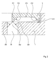
- the chuck shown in the drawing has a chuck body 1 which can be fastened by means of a recess 2 with the aid of screws 3 on the end face of a lathe spindle, not shown.
- Radially clamping jaws 4 are guided in the chuck body 1, only one of which is shown in the drawing.
- an axially adjustable drive member 5 is provided in the chuck body 1.
- the drive member 5 is in engagement with the clamping jaws 4 via a wedge hook connection, the wedge hook 6 being firmly seated on the drive member 5 and the wedge hook 7 being firmly seated on the clamping jaw 4.
- the drive member 5 is shown in its right end position. This corresponds to the outer radial end position of the clamping jaws 4, that is to say the external state of the workpiece, not shown, the open state of the chuck.
- the clamping jaws 4 move radially inward and clamp the workpiece.
- the clamping stroke of the drive member 5 is therefore directed to the left in the drawing.
- other suitable drive connections can also be used.
- a connection ring 11 is rotatably mounted on the outside of the chuck body 1 and has connection openings 11 'for the supply and discharge of the pressure medium. If the pressure medium reaches the cylinder space 8b located on the right side of the tensioning piston 9, the tensioning stroke takes place, in the other case the release stroke. The situation turns accordingly, if instead of the assumed external clamping an internal clamping should take place, the clamping stroke of the clamping jaws 4 is therefore directed radially outwards.
- a function control device acting on the rotary drive of the machine is provided for monitoring the clamping process. It comprises a sensor 18 which is fixed outside the chuck, a switching element 17 which actuates the sensor and is arranged on the outer circumference of the chuck body and a control piston 12 which adjusts the switching element and which is acted upon by the pressure medium of the clamping piston 9 against the force of a return spring 13, for which purpose between the cylinder spaces 8a, 8b of the tensioning piston 9 and the cylinder space 14 of the control piston 12 are suitable, in the drawing only recognizable at 15 connecting channels.
- the control piston 12 is locked against displacements caused by the pressure medium in a blocking position that switches off the rotary drive, or is adjustable into this blocking position if the drive member 5 is at the ends of its axial stroke path in two safety areas indicated by the double arrows 16 in the drawing.
- the part of the axial stroke corresponding to the working range of the drive member 5 is indicated by the double arrow 16 '.
- the control piston 12 is arranged such that it can be displaced parallel to the chuck axis and is coupled via a wedge gear 19 to a control pin 20 guided in the chuck body 1 and displaceable radially to the chuck axis.
- This control pin 20 is associated with a control cam 21 which is moved with the drive member 5 and which acts as a stop for limiting the radially inward displacement path of the control pin 20.
- the wedge gear 19 is so formed that a displacement of the control piston 12 from its locked position is connected with a radially inward displacement of the control pin 20.
- the control piston 12 and the control pin 20 are positively guided together by the wedge gear, so that the positions of the control piston 12 and the control pin 20 are clearly assigned to one another.
- the wedge gear 19 consists of a wedge web 19.1 arranged inclined to the axes of the control piston 12 and control bolt 20 and a wedge groove 19.2 receiving it, which are only indicated by dashed lines in the drawing, since depending on the suitability of the wedge web 19.1 either on the control piston 12 or on Control pin 20 and accordingly the keyway 19.2 can be located on the control pin 20 or control piston 12.
- the switching element 17 is a switching cam which projects radially over the lateral surface of the chuck body 1 and is guided in an axial groove 23 of the chuck body and is connected to the control rod 22 by means of a screw 25 through a slot 24 in the groove bottom.
- the sensor 18 is designed as an inductive proximity switch, which is controlled by the switching element 17 without contact.
- control piston 12 has an axially from the front end face 1 'of the chuck body 1 projecting piston neck 26, in which there is an adjustment screw 27 accessible from the front face 1' with which the Force of the return spring 13 is adjustable.
- the return spring 13 lies in a longitudinal bore 28 of the control piston 12, in which the return spring 13 in the form of a helical spring is supported against the adjusting screw 13 by means of an abutment 29 which can be displaced in the longitudinal bore 28.
- the other end of the return spring 13 protruding from the longitudinal bore 28 is supported on the chuck body 1, for which purpose the chuck body 1 is provided with a receptacle 30 centering the spring end.
- the pressurized cylinder space 14 of the control piston 12 is formed by a in the chuck body 1 to its end face 1 'open bore, which is closed on the end face by a cylinder cover 31, through which the piston neck 26 is sealed.
- the cylinder cover 31 is flush with the end face 1 'of the chuck body 1.
- the return spring 13 acts axially forward on the control piston 12 and the control pin 20 radially outward via the wedge gear 19.
- the control piston 12 is in the front end position, which corresponds to its locked position. From this blocking position, the control piston 12 can only move to the left in the drawing under the action of the pressure medium and release the rotary drive of the machine via the control rod 22 and the switching element 17 as well as the sensor 18 when the control pin 20 is correspondingly radially inward via the wedge gear 19 is adjustable, that is to say this adjustment is not prevented by a stop on the control cam 21.
- control cam 21 is provided in the area of both axial curve ends with radially outward control projections 21.1, the axial length of which in each case Security areas 16 of the axial stroke of the drive member 5 corresponds.
- These control projections 21.1 connect via run-up slopes 21.2 to the part 21.3 of the control cam corresponding to the working area 16 'of the drive member 5.
- Corresponding bevels 20.1 are provided on the cam 20 lying against the head 20.2 of the control pin 20, so that when the drive member 5 is moved from the working area 16 'into one of the two security areas 16 of the control pin 20 radially outwards through these run-up slopes and thus the control piston 12 the wedge gear 19 is pressed axially forward against the force of the pressure medium in the locking position.
- the control cam 21 is formed by the bottom of a control groove 21.4 which runs axially on the drive member 5 and into which the control pin 20 engages with its bolt head 20.2 which carries the run-up bevels 20.1.
- the function control device checks two prerequisites for the effective clamping of a workpiece, namely whether the clamping member 5 is really in the working area, that is to say it has left the safety areas 16, and whether the clamping pressure is of sufficient size.
- the release of the rotary drive that is to say the adjustment of the control piston 12 in the drawing to the left, presupposes that the force exerted on the control piston 12 by the pressure medium exceeds the opposite force of the return spring 13.
- the force of the return spring 13 thus corresponds to a minimum clamping pressure assigned to the chuck.
- the size of this minimum clamping pressure can be adjusted by adjusting the force of the Return spring 13 can be selected accordingly.
- the control is carried out with the chuck rotating and at a standstill, the chuck in the latter case merely being positioned so that the switching element 17 faces the sensor 18. - If both conditions are met, the control piston 12 and thus also the switching element 17 are in their axially rearward end position, in which the sensor 18 is not activated. The rotary drive of the machine is released. However, if only one of the two requirements is met, the control piston 12 and the switching element 17 remain in their front end position shown in the drawing, the sensor 18 being activated and causing the machine to come to a standstill.
Landscapes
- Engineering & Computer Science (AREA)
- Mechanical Engineering (AREA)
- Gripping On Spindles (AREA)
Applications Claiming Priority (2)
| Application Number | Priority Date | Filing Date | Title |
|---|---|---|---|
| DE3725714 | 1987-08-04 | ||
| DE3725714A DE3725714C1 (fr) | 1987-08-04 | 1987-08-04 |
Publications (2)
| Publication Number | Publication Date |
|---|---|
| EP0302187A1 true EP0302187A1 (fr) | 1989-02-08 |
| EP0302187B1 EP0302187B1 (fr) | 1990-10-17 |
Family
ID=6332963
Family Applications (1)
| Application Number | Title | Priority Date | Filing Date |
|---|---|---|---|
| EP88107289A Expired - Lifetime EP0302187B1 (fr) | 1987-08-04 | 1988-05-06 | Dispositif de serrage sur tours avec mandrin |
Country Status (5)
| Country | Link |
|---|---|
| US (1) | US4932674A (fr) |
| EP (1) | EP0302187B1 (fr) |
| JP (1) | JPH0659564B2 (fr) |
| DE (1) | DE3725714C1 (fr) |
| ES (1) | ES2018863B3 (fr) |
Families Citing this family (10)
| Publication number | Priority date | Publication date | Assignee | Title |
|---|---|---|---|---|
| US6257595B1 (en) | 1998-09-04 | 2001-07-10 | Hardinge Inc. | Collect chuck with quick-change cap |
| US6202523B1 (en) | 1998-11-10 | 2001-03-20 | J. F. Berns Co., Inc. | Air operated loading and unloading device |
| DE10163104A1 (de) * | 2001-12-20 | 2003-07-03 | Roemheld A Gmbh & Co Kg | Zentrierspannelement |
| DE10207567A1 (de) * | 2002-02-22 | 2003-09-04 | Roehm Gmbh | Kugelbolzenfutter |
| DE10307565A1 (de) * | 2002-10-09 | 2004-04-22 | Smw-Autoblok Spannsysteme Gmbh | Kraftspannfutter oder dgl. |
| US7513181B2 (en) * | 2003-11-24 | 2009-04-07 | J.F. Berns Co., Inc. | Air operated unloading device |
| FR2883359B1 (fr) * | 2005-03-15 | 2007-05-11 | Valeo Vision Sa | Projecteur lumineux pour vehicule automobile, de faible encombrement |
| CN102581328B (zh) * | 2012-03-14 | 2013-12-04 | 赵长军 | 前置摆动缸式中空液压卡盘 |
| CN103769639B (zh) * | 2014-02-14 | 2015-07-29 | 哈尔滨工业大学 | 带双向限位的外卡式精密电动卡盘 |
| CN103785873B (zh) * | 2014-02-14 | 2015-07-29 | 哈尔滨工业大学 | 精密气动卡盘 |
Citations (3)
| Publication number | Priority date | Publication date | Assignee | Title |
|---|---|---|---|---|
| DE3102099A1 (de) * | 1981-01-23 | 1982-08-19 | Röhm GmbH, 7927 Sontheim | Spanneinrichtung an drehmaschinen mit einem spannfutter |
| DE3518332C1 (de) * | 1985-05-22 | 1986-05-22 | Paul Forkardt GmbH & Co KG, 4000 Düsseldorf | Umlaufendes Kraftspannfutter, insbesondere für Drehmaschinen |
| DE3228749C2 (de) * | 1982-07-31 | 1986-10-16 | Paul Forkardt GmbH & Co KG, 4000 Düsseldorf | Einrichtung zur Bestimmung des Arbeitsbereiches eines doppeltwirkenden Spannzylinders zur Betätigung von Spanneinrichtungen an Werkzeugmaschinen, insbesondere von auswechselbaren Spannfuttern an Drehmaschinen |
Family Cites Families (3)
| Publication number | Priority date | Publication date | Assignee | Title |
|---|---|---|---|---|
| DE2924111C2 (de) * | 1979-06-15 | 1986-07-17 | SMW Schneider & Weißhaupt GmbH, 7996 Meckenbeuren | Einrichtung zur Überwachung des Druckes bei druckmittelbetätigten Spannfuttern mit im Betrieb rotierenden Spannzylindern an Bearbeitungsmaschinen |
| DE3402989A1 (de) * | 1984-01-28 | 1985-08-08 | SMW Schneider & Weißhaupt GmbH, 7996 Meckenbeuren | Einrichtung zur ueberwachung des betriebszustandes eines kraftspannfutters |
| DE3402988A1 (de) * | 1984-01-28 | 1985-08-08 | SMW Schneider & Weißhaupt GmbH, 7996 Meckenbeuren | Einrichtung zur ueberwachung des betriebszustandes eines kraftspannfutters |
-
1987
- 1987-08-04 DE DE3725714A patent/DE3725714C1/de not_active Expired
-
1988
- 1988-05-06 EP EP88107289A patent/EP0302187B1/fr not_active Expired - Lifetime
- 1988-05-06 ES ES88107289T patent/ES2018863B3/es not_active Expired - Lifetime
- 1988-08-02 JP JP63194311A patent/JPH0659564B2/ja not_active Expired - Fee Related
- 1988-08-04 US US07/228,904 patent/US4932674A/en not_active Expired - Lifetime
Patent Citations (3)
| Publication number | Priority date | Publication date | Assignee | Title |
|---|---|---|---|---|
| DE3102099A1 (de) * | 1981-01-23 | 1982-08-19 | Röhm GmbH, 7927 Sontheim | Spanneinrichtung an drehmaschinen mit einem spannfutter |
| DE3228749C2 (de) * | 1982-07-31 | 1986-10-16 | Paul Forkardt GmbH & Co KG, 4000 Düsseldorf | Einrichtung zur Bestimmung des Arbeitsbereiches eines doppeltwirkenden Spannzylinders zur Betätigung von Spanneinrichtungen an Werkzeugmaschinen, insbesondere von auswechselbaren Spannfuttern an Drehmaschinen |
| DE3518332C1 (de) * | 1985-05-22 | 1986-05-22 | Paul Forkardt GmbH & Co KG, 4000 Düsseldorf | Umlaufendes Kraftspannfutter, insbesondere für Drehmaschinen |
Also Published As
| Publication number | Publication date |
|---|---|
| JPH0659564B2 (ja) | 1994-08-10 |
| DE3725714C1 (fr) | 1988-06-23 |
| JPS6451210A (en) | 1989-02-27 |
| ES2018863B3 (es) | 1991-05-16 |
| US4932674A (en) | 1990-06-12 |
| EP0302187B1 (fr) | 1990-10-17 |
Similar Documents
| Publication | Publication Date | Title |
|---|---|---|
| DE4313742C1 (de) | Bohrfutter | |
| DE2711904C3 (de) | Spannfutter für Drehmaschinen | |
| EP2370222B1 (fr) | Porte-outil | |
| EP0620068B1 (fr) | Mandrin de perçage | |
| EP0677348A1 (fr) | Mandrin de perçage | |
| EP0151791B1 (fr) | Mandrin de serrage, en particulier mandrin porte-foret | |
| DE2533803B2 (de) | Kraftbetätigtes Keilspannfutter | |
| DE3501416C2 (de) | Spannfutter-Aufsatzbacken-Wechseleinrichtung | |
| EP0302187B1 (fr) | Dispositif de serrage sur tours avec mandrin | |
| EP1572403B1 (fr) | Mandrin de serrage et tige de serrage destinee a celui-ci | |
| DE69310579T2 (de) | Werkzeug-Ein- und Ausspannvorrichtung | |
| EP0008318A1 (fr) | Mandrin de serrage pour machines à tourner | |
| EP0005458B1 (fr) | Mandrin de serrage pour machines à tourner | |
| EP0175065A1 (fr) | Mandrin réglable | |
| DE3709299C2 (fr) | ||
| DE2648997A1 (de) | Spannwerkzeug mit einzelverstellung und zusaetzlicher zentralspannung | |
| DE2736753A1 (de) | Spannfutter fuer drehmaschinen | |
| DE3323709C2 (de) | Gewindeschneidfutter | |
| DE2916179C2 (de) | Spanneinrichtung, insbesondere Maschinenschraubstock | |
| DE2817368C2 (de) | Spannfutter für Drehmaschinen | |
| DE3438145C1 (de) | Bohrfutter,insbesondere Schlagbohrfutter | |
| DE3425609A1 (de) | Spannfutter | |
| DE2937194A1 (de) | Werkstueckspannanordnung fuer drehmaschinen | |
| DE2821848A1 (de) | Spannfutter fuer drehmaschinen | |
| DE1602755C3 (de) | Bohrkopf mit einem Spindelschaft |
Legal Events
| Date | Code | Title | Description |
|---|---|---|---|
| PUAI | Public reference made under article 153(3) epc to a published international application that has entered the european phase |
Free format text: ORIGINAL CODE: 0009012 |
|
| AK | Designated contracting states |
Kind code of ref document: A1 Designated state(s): ES FR GB IT SE |
|
| 17P | Request for examination filed |
Effective date: 19890124 |
|
| 17Q | First examination report despatched |
Effective date: 19900404 |
|
| GRAA | (expected) grant |
Free format text: ORIGINAL CODE: 0009210 |
|
| AK | Designated contracting states |
Kind code of ref document: B1 Designated state(s): ES FR GB IT SE |
|
| ITF | It: translation for a ep patent filed | ||
| ET | Fr: translation filed | ||
| GBT | Gb: translation of ep patent filed (gb section 77(6)(a)/1977) | ||
| PLBE | No opposition filed within time limit |
Free format text: ORIGINAL CODE: 0009261 |
|
| STAA | Information on the status of an ep patent application or granted ep patent |
Free format text: STATUS: NO OPPOSITION FILED WITHIN TIME LIMIT |
|
| 26N | No opposition filed | ||
| ITTA | It: last paid annual fee | ||
| EAL | Se: european patent in force in sweden |
Ref document number: 88107289.6 |
|
| PGFP | Annual fee paid to national office [announced via postgrant information from national office to epo] |
Ref country code: SE Payment date: 19950405 Year of fee payment: 8 |
|
| PGFP | Annual fee paid to national office [announced via postgrant information from national office to epo] |
Ref country code: ES Payment date: 19950424 Year of fee payment: 8 |
|
| PGFP | Annual fee paid to national office [announced via postgrant information from national office to epo] |
Ref country code: FR Payment date: 19950510 Year of fee payment: 8 |
|
| PG25 | Lapsed in a contracting state [announced via postgrant information from national office to epo] |
Ref country code: SE Effective date: 19960507 Ref country code: ES Free format text: LAPSE BECAUSE OF NON-PAYMENT OF DUE FEES Effective date: 19960507 |
|
| PG25 | Lapsed in a contracting state [announced via postgrant information from national office to epo] |
Ref country code: FR Effective date: 19970131 |
|
| EUG | Se: european patent has lapsed |
Ref document number: 88107289.6 |
|
| REG | Reference to a national code |
Ref country code: FR Ref legal event code: ST |
|
| REG | Reference to a national code |
Ref country code: ES Ref legal event code: FD2A Effective date: 19990405 |
|
| PGFP | Annual fee paid to national office [announced via postgrant information from national office to epo] |
Ref country code: GB Payment date: 20000425 Year of fee payment: 13 |
|
| PG25 | Lapsed in a contracting state [announced via postgrant information from national office to epo] |
Ref country code: GB Free format text: LAPSE BECAUSE OF NON-PAYMENT OF DUE FEES Effective date: 20010506 |
|
| GBPC | Gb: european patent ceased through non-payment of renewal fee |
Effective date: 20010506 |
|
| PG25 | Lapsed in a contracting state [announced via postgrant information from national office to epo] |
Ref country code: IT Free format text: LAPSE BECAUSE OF NON-PAYMENT OF DUE FEES Effective date: 20050506 |