EP0302192A1 - Dispositif de traitement des êtres vivants et des plantes avec l'énergie de pyramide - Google Patents
Dispositif de traitement des êtres vivants et des plantes avec l'énergie de pyramideInfo
- Publication number
- EP0302192A1 EP0302192A1 EP19880108443 EP88108443A EP0302192A1 EP 0302192 A1 EP0302192 A1 EP 0302192A1 EP 19880108443 EP19880108443 EP 19880108443 EP 88108443 A EP88108443 A EP 88108443A EP 0302192 A1 EP0302192 A1 EP 0302192A1
- Authority
- EP
- European Patent Office
- Prior art keywords
- pyramid
- energy
- electrode
- chakra
- energy absorption
- Prior art date
- Legal status (The legal status is an assumption and is not a legal conclusion. Google has not performed a legal analysis and makes no representation as to the accuracy of the status listed.)
- Withdrawn
Links
Images


Classifications
-
- A—HUMAN NECESSITIES
- A61—MEDICAL OR VETERINARY SCIENCE; HYGIENE
- A61N—ELECTROTHERAPY; MAGNETOTHERAPY; RADIATION THERAPY; ULTRASOUND THERAPY
- A61N1/00—Electrotherapy; Circuits therefor
- A61N1/16—Screening or neutralising undesirable influences from or using, atmospheric or terrestrial radiation or fields
Definitions
- the invention relates to a device for treating living beings and plants by pyramid energy, in which at least one energy tap is provided on the outside of the pyramid, from which an electrical line leads to a chakra electrode.
- a device for treating living beings and plants by pyramid energy in which at least one energy tap is provided on the outside of the pyramid, from which an electrical line leads to a chakra electrode.
- Such a device is the subject of DE-OS 35 30 841.
- the energy is tapped on the lateral surface of a cup which acts as a vibrating pot and which is placed on the pyramid from above.
- the fact that energy is present between the chakra electrodes by means of the known device could be demonstrated by measuring the radioactivity of a water sample, by placing an identical sample outside the device and measuring the radioactivity over time. In contrast to the other sample, the sample between the chakra electrodes showed a rapid drop in radioactivity within a short time.
- the previously known device is used for the therapy of humans and has led to astonishing healing success.
- a disadvantage of the known device is that this is relatively expensive to manufacture due to the attached cup, which must consist of an expensive brass alloy or other, sometimes even more expensive materials, so that it could not find the distribution for cost reasons would be appropriate due to their good therapeutic effects.
- the invention has for its object to design a device of the type mentioned in such a way that the pyramid energy can be tapped from the pyramid with as little effort as possible and which has the highest possible effectiveness.
- the energy tap is provided on an energy supply line running along an edge of the pyramid and galvanically separated from the pyramid.
- the energy absorption lines which can be formed by simple, non-insulated copper wires running at a short distance from the pyramid edges, can be produced much more cheaply than the known cup, which acts as an oscillating pot and is placed on the pyramid. Therefore, a pyramid energy system according to the invention is considerably cheaper to manufacture than the known device.
- a therapeutically advantageous device is characterized in that an energy tap is provided at the two ends of the energy intake line and the upper energy tap is connected to an upper chakra electrode and the lower energy tap is connected to a lower chakra electrode.
- an energy absorption line with two energy taps is provided along each edge of the pyramid and the upper energy taps are connected to four individual electrodes of the upper chakra electrode and the lower energy taps are connected to four individual electrodes of the lower chakra electrode.
- This design allows therapeu with even better effects, because different energies are emitted at the individual edges, which are led to the individual electrodes without mutual interference.
- a mutual influence of the energies absorbed by the cup is to be expected in the cup acting as a vibrating pot.
- the energies are radiated at right angles to the pyramid edge, it is advantageous if the energy taps are provided at the height of the pyramid tip and the pyramid base at the end of a right-angled bend in the energy absorption line.
- the transmitted energy receives a twist corresponding to the chakra centers when the bends are turned clockwise like a corkscrew.
- the outgoing lines can design the outgoing lines as right-handed conductors or lead the outgoing lines as a whole to the chakra electrodes in a right-handed manner.
- the energy-receiving lines can be held in a very simple manner at a fixed distance from the respective pyramid edge if, according to another embodiment of the invention, the energy-receiving lines are each held with a partial area of their two angles formed by the bends in a slot of an insulating piece at the pyramid tip and the pyramid base are.
- the insulating pieces provided at the base of the pyramid on each edge each grip with a rectangular recess over a corner of the pyramid and have in their surface the slot which receives the energy absorption line.
- the energy emitted by the pyramid tip can also be collected in a simple manner and can thus be used if the insulating piece provided on the top of the pyramid has an energy-absorbing electrode which is galvanically separated from the pyramid and is aligned coaxially to the pyramid axis and is turned clockwise in the manner of a corkscrew.
- the upper insulating piece is particularly simple if it is a cylinder with a coaxial bore for receiving the energy absorption electrode and with four radial slots for the energy absorption lines and if the end face of the insulating piece facing the pyramid tip is designed as an inner cone in accordance with the pyramid inclination.
- the effect of the pyramid energy system is particularly great if, in accordance with another embodiment of the invention, the upper chakra electrode has a central individual electrode in addition to the four individual electrodes connected to the upper energy taps the energy absorption electrode of the pyramid tip is connected and, depending on the pyramid height, extends deeper than the other individual electrodes.
- the device according to the invention can also be produced more cost-effectively than the previously known devices because the upper chakra electrode only needs five and the lower chakra electrode only four individual electrodes.
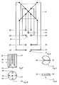
- the device shown in Figure 1 has a base plate 1 with wheels 2, 3. On this base plate 1 is rotatable about a vertical axis 4, a support 5 is arranged, on which a pyramid 6 made of copper, for example. Before the support 5, a tripod 7 is attached to the base plate 1, which holds an upper chakra electrode 8 and a lower chakra electrode 9. The pyramid energy is supplied to the two chakra electrodes 8, 9 via lines 10, 11. The type of energy absorption from the pyramid 6 is important for the invention. This can be seen most clearly from FIGS. 2 and 3.
- FIG. 2 shows that an energy absorption line 12, 13 runs parallel to the edges of the pyramid 6, which is at the top of the pyramid from an upper insulating piece 14 common to all four energy absorption lines 12, 13 and at the corners of the base of the pyramid 6 each through lower insulating piece 15, 16 are held.
- Each energy supply line 12, 13 consists of a non-insulated wire section 17 running parallel to the pyramid edge and a right-angled bend 18, 19 which is corkscrew-like, clockwise and each has a plug connection 20, 21 at its end.
- the upper insulating piece 14 of the pyramid 6 carries, coaxially to the pyramid 6, an energy absorption electrode 38 which is formed from a right-handed spiral, corkscrew-like piece of wire pointing upward in the main direction of extension, at the end of which a plug connection 39 is also provided as an energy tap.
- FIG. 3 shows that in addition to the insulating pieces 15, 16, corresponding insulating pieces 22, 23 are also provided at the two other corners of the pyramid 6.
- These insulating pieces 15, 16, 22, 23 each have a slot in their upper side, for example a slot 24 in the insulating piece 15, in each of which an energy absorption line, for example the energy absorption line 17, sits with a partial region of the angle formed by the bend 18.
- Corresponding slots 25 - 28 are provided in a radial orientation in the lateral surface of the upper insulating piece 14, in which the respective upper angle of each energy absorption line 12, 13 is seated.
- FIGS. 4 and 5 show that the upper chakra electrode 8 consists of a total of five individual electrodes 29-33, the middle individual electrode 33 reaching further down by the height of the pyramid 6 than the other individual electrodes 29, 30, 31, 32 .
- the lower chakra electrode 9 shown in FIGS. 6 and 7 consists of four individual electrodes 34-37, which are aligned with the individual electrodes 29-32.
- FIG. 8 illustrates how the individual electrodes 29-37 are connected to the energy taps of the pyramid 6.
- the respective upper energy taps of the energy absorption lines 12, 13 guided along the pyramid edges and the energy tapping of the energy absorption electrode 38 on the top of the pyramid 6 are with the upper chakra electrode 8 and the other energy taps, ie the four energy taps provided on the underside of the energy absorption lines 12, 13 are connected to the lower chakra electrode 9. If one imagines the pyramid 6 with the tip pointing downward between the chakra electrodes 8, 9, then all connecting lines lead to the respective individual electrodes 29-37 without crossing each other.
- FIG. 9 illustrates the design of the upper insulating piece 14. It can be seen that a bore 40 leads coaxially through it, which opens at the bottom into an inner cone 41 which is dimensioned such that the insulating piece 14 is well on the tip the pyramid 6 can be set.
- FIG. 9 also shows the two slots 25, 27 and FIG. 10 all four radial slots 25-28.
- FIGS. 11 and 12 show the example of the lower insulating piece 15 that the lower insulating pieces 15, 16, 22, 23 each have an angular recess 42 with which they are able to grip around a corner of the pyramid 6. Furthermore, FIGS. 11 and 12 show the slot 24, in which the energy absorption line 12 is inserted with a corner.
Landscapes
- Health & Medical Sciences (AREA)
- Engineering & Computer Science (AREA)
- Biomedical Technology (AREA)
- Nuclear Medicine, Radiotherapy & Molecular Imaging (AREA)
- Radiology & Medical Imaging (AREA)
- Life Sciences & Earth Sciences (AREA)
- Animal Behavior & Ethology (AREA)
- General Health & Medical Sciences (AREA)
- Public Health (AREA)
- Veterinary Medicine (AREA)
- Electrotherapy Devices (AREA)
Applications Claiming Priority (2)
| Application Number | Priority Date | Filing Date | Title |
|---|---|---|---|
| DE8709761 | 1987-07-16 | ||
| DE8709761U | 1987-07-16 |
Publications (1)
| Publication Number | Publication Date |
|---|---|
| EP0302192A1 true EP0302192A1 (fr) | 1989-02-08 |
Family
ID=6810109
Family Applications (1)
| Application Number | Title | Priority Date | Filing Date |
|---|---|---|---|
| EP19880108443 Withdrawn EP0302192A1 (fr) | 1987-07-16 | 1988-05-27 | Dispositif de traitement des êtres vivants et des plantes avec l'énergie de pyramide |
Country Status (1)
| Country | Link |
|---|---|
| EP (1) | EP0302192A1 (fr) |
Cited By (5)
| Publication number | Priority date | Publication date | Assignee | Title |
|---|---|---|---|---|
| WO1992012761A1 (fr) * | 1991-01-28 | 1992-08-06 | Gabor Kolar | Dispositif pour accelerer la croissance |
| WO1995011585A1 (fr) * | 1993-10-25 | 1995-05-04 | Abo-Center (Ltd) | Procede de traitement preliminaire de graines destinees a etre plantees |
| WO1996032192A1 (fr) * | 1995-04-11 | 1996-10-17 | Vladimir Vasilievich Uvarov | Dispositif permettant d'influencer la structure d'objets materiels |
| WO2001010497A1 (fr) * | 2000-02-14 | 2001-02-15 | Bauer Armin C | Generateur a pyramides |
| NL2000465C2 (nl) * | 2007-02-01 | 2008-08-04 | Joseph Maria Tol | Inrichting voor het opwekken van een coherentieverhogend energieveld en stelsel van een dergelijke inrichting en een of meer behandelinstrumenten. |
Citations (6)
| Publication number | Priority date | Publication date | Assignee | Title |
|---|---|---|---|---|
| FR1057531A (fr) * | 1952-05-30 | 1954-03-09 | Appareil dérivateur d'ondes telluriques | |
| FR1108193A (fr) * | 1954-08-11 | 1956-01-10 | Dispositif de protection contre les radiations nocives | |
| FR2264406A1 (en) * | 1974-03-15 | 1975-10-10 | Fantuzzi Giuseppe | Device concentrating and radiating stray energy - has geometrically shaped pick up surface with coils connected to diffusors and aerial |
| DE3006191A1 (de) * | 1979-02-23 | 1980-09-04 | Gerard Ohresser | Vorrichtung zur adsorption von strahlungen |
| DE3416157A1 (de) * | 1984-05-02 | 1986-02-20 | Trude 7519 Walzbachtal Roth | Erdstrahlenentstoerungsgeraet |
| DE3433292A1 (de) * | 1984-09-11 | 1986-03-20 | Rehm, Siegfried, 5657 Haan | Geraet zur gerichteten ablenkung bzw. abschirmung von sog. erdstrahlen - geopathogenen zonen - u. anderer stoerquellen wie fernsehantenne u. hochspannungsmasten u. anderer strahler |
-
1988
- 1988-05-27 EP EP19880108443 patent/EP0302192A1/fr not_active Withdrawn
Patent Citations (6)
| Publication number | Priority date | Publication date | Assignee | Title |
|---|---|---|---|---|
| FR1057531A (fr) * | 1952-05-30 | 1954-03-09 | Appareil dérivateur d'ondes telluriques | |
| FR1108193A (fr) * | 1954-08-11 | 1956-01-10 | Dispositif de protection contre les radiations nocives | |
| FR2264406A1 (en) * | 1974-03-15 | 1975-10-10 | Fantuzzi Giuseppe | Device concentrating and radiating stray energy - has geometrically shaped pick up surface with coils connected to diffusors and aerial |
| DE3006191A1 (de) * | 1979-02-23 | 1980-09-04 | Gerard Ohresser | Vorrichtung zur adsorption von strahlungen |
| DE3416157A1 (de) * | 1984-05-02 | 1986-02-20 | Trude 7519 Walzbachtal Roth | Erdstrahlenentstoerungsgeraet |
| DE3433292A1 (de) * | 1984-09-11 | 1986-03-20 | Rehm, Siegfried, 5657 Haan | Geraet zur gerichteten ablenkung bzw. abschirmung von sog. erdstrahlen - geopathogenen zonen - u. anderer stoerquellen wie fernsehantenne u. hochspannungsmasten u. anderer strahler |
Cited By (6)
| Publication number | Priority date | Publication date | Assignee | Title |
|---|---|---|---|---|
| WO1992012761A1 (fr) * | 1991-01-28 | 1992-08-06 | Gabor Kolar | Dispositif pour accelerer la croissance |
| WO1995011585A1 (fr) * | 1993-10-25 | 1995-05-04 | Abo-Center (Ltd) | Procede de traitement preliminaire de graines destinees a etre plantees |
| WO1996032192A1 (fr) * | 1995-04-11 | 1996-10-17 | Vladimir Vasilievich Uvarov | Dispositif permettant d'influencer la structure d'objets materiels |
| WO2001010497A1 (fr) * | 2000-02-14 | 2001-02-15 | Bauer Armin C | Generateur a pyramides |
| NL2000465C2 (nl) * | 2007-02-01 | 2008-08-04 | Joseph Maria Tol | Inrichting voor het opwekken van een coherentieverhogend energieveld en stelsel van een dergelijke inrichting en een of meer behandelinstrumenten. |
| WO2008094038A3 (fr) * | 2007-02-01 | 2008-09-25 | Joseph Maria Tol | Dispositif pour générer un champ d'énergie, système d'un tel dispositif et un ou plusieurs instruments de traitement |
Similar Documents
| Publication | Publication Date | Title |
|---|---|---|
| EP0406919B1 (fr) | Dispositif pour contrÔler électroniquement des circuits imprimés comportant des pointes de contact à module extrêmement fin | |
| EP0108383B1 (fr) | Dispositif implantable pour la stimulation de la croissance des os | |
| WO2020147880A1 (fr) | Dispositif de traitement au plasma et procédé d'adaptation de la taille d'une surface d'appui du dispositif de traitement au plasma adapté à la taille de la surface à traiter | |
| DE3132488C2 (fr) | ||
| EP0085935A2 (fr) | Fiche pour voyageur | |
| DE3425896A1 (de) | Elektrokochplatte | |
| DE2747539A1 (de) | Elektrodenanordnung zur induktiven abstandsmessung | |
| DE2733200C3 (de) | Antennensteckdose | |
| EP1616060A1 (fr) | Dispositif pour recevoir et diffuser des formes d'energie libres | |
| DE859037C (de) | Eine Roehrenschaltung enthaltender Steckbauteil | |
| DE1302004B (de) | Elektrische Klemmverbindung zwischen isolierten Leitungsdraehten und einem metallischen Stuetzpunkt | |
| EP0054115B1 (fr) | Support de fil, particulièrement pour clôtures capacitives de protection | |
| DE8711136U1 (de) | Vorrichtung zur Behandlung von Lebewesen und Pflanzen durch Pyramidenenergie | |
| DE706208C (de) | Anordnung zur Befestigung elektrischer Entladungsroehren mit einem Vakuumgefaess aus Metall an einem Traeger | |
| CH658790A5 (de) | Schutzvorrichtung. | |
| DE8609086U1 (de) | Sicherungshalter | |
| DE4028948C2 (fr) | ||
| EP0432785B1 (fr) | Dispositif de fixation d'un ressort de support | |
| WO1994006509A1 (fr) | Implant d'electrostimulation de tissus | |
| DE4121331A1 (de) | Kontaktklemme | |
| DE2724655A1 (de) | Traegerkoerper als halbfabrikat fuer unterschiedliche schaltkreis-elemente der elektronischen technik | |
| DE2613217A1 (de) | Kontaktleiste | |
| DE2246354C2 (de) | Motor-Drehwähler | |
| EP0287687A1 (fr) | Dispositif pour le traitement par énergie pyramidale des êtres vivants et des plantes | |
| DE2345363B1 (de) | Vorrichtung zur Befestigung eines Kabels oder anderen langgestreckten Koerpers auf einer Unterlage |
Legal Events
| Date | Code | Title | Description |
|---|---|---|---|
| PUAI | Public reference made under article 153(3) epc to a published international application that has entered the european phase |
Free format text: ORIGINAL CODE: 0009012 |
|
| AK | Designated contracting states |
Kind code of ref document: A1 Designated state(s): AT BE CH DE ES FR GB GR IT LI LU NL SE |
|
| 17P | Request for examination filed |
Effective date: 19890316 |
|
| STAA | Information on the status of an ep patent application or granted ep patent |
Free format text: STATUS: THE APPLICATION IS DEEMED TO BE WITHDRAWN |
|
| 18D | Application deemed to be withdrawn |
Effective date: 19921201 |