EP0302208B1 - Machine axiale à pistons avec partitions angulaires différentes pour les pistons, respectivement les cylindres-pistons - Google Patents
Machine axiale à pistons avec partitions angulaires différentes pour les pistons, respectivement les cylindres-pistons Download PDFInfo
- Publication number
- EP0302208B1 EP0302208B1 EP88109854A EP88109854A EP0302208B1 EP 0302208 B1 EP0302208 B1 EP 0302208B1 EP 88109854 A EP88109854 A EP 88109854A EP 88109854 A EP88109854 A EP 88109854A EP 0302208 B1 EP0302208 B1 EP 0302208B1
- Authority
- EP
- European Patent Office
- Prior art keywords
- pistons
- piston
- axial piston
- piston machine
- pitch circle
- Prior art date
- Legal status (The legal status is an assumption and is not a legal conclusion. Google has not performed a legal analysis and makes no representation as to the accuracy of the status listed.)
- Expired - Lifetime
Links
- 238000005192 partition Methods 0.000 title 1
- 239000011295 pitch Substances 0.000 claims 12
- 230000010349 pulsation Effects 0.000 description 4
- 230000008901 benefit Effects 0.000 description 2
- 239000012530 fluid Substances 0.000 description 2
- 239000000463 material Substances 0.000 description 2
- 238000010276 construction Methods 0.000 description 1
- 238000011161 development Methods 0.000 description 1
- 230000018109 developmental process Effects 0.000 description 1
- 239000002184 metal Substances 0.000 description 1
- 230000000149 penetrating effect Effects 0.000 description 1
Images

Classifications
-
- F—MECHANICAL ENGINEERING; LIGHTING; HEATING; WEAPONS; BLASTING
- F01—MACHINES OR ENGINES IN GENERAL; ENGINE PLANTS IN GENERAL; STEAM ENGINES
- F01B—MACHINES OR ENGINES, IN GENERAL OR OF POSITIVE-DISPLACEMENT TYPE, e.g. STEAM ENGINES
- F01B3/00—Reciprocating-piston machines or engines with cylinder axes coaxial with, or parallel or inclined to, main shaft axis
- F01B3/02—Reciprocating-piston machines or engines with cylinder axes coaxial with, or parallel or inclined to, main shaft axis with wobble-plate
Definitions
- the invention relates to an axial piston machine according to the preamble of claim 1.
- the invention has for its object to design an axial piston machine of the type mentioned in such a way that the running noise of the axial piston machine can be reduced while ensuring the smallest possible construction.
- the desired reduction in running noise results from different angular divisions of the pistons.
- This advantage benefits the pistons on both pitch circles because they are arranged in the gaps of the largest angular divisions of the adjacent pitch circle.
- the initially recognizable disadvantage of an uneven distribution of the pistons namely a poorer utilization of the available space due to the cylinder size specified by the minimum spacing of two adjacent pistons required for strength, is at least largely eliminated in the embodiment according to the invention in that the pistons in the area of the gaps of the largest Angular divisions of the adjacent pitch circle are arranged.
- the pistons can be arranged in the same number, unequal number and also in the same or unequal groups with respect to both partial circles, in which the angular divisions are the same, but the angular divisions from piston group to piston group are different.
- an axial piston machine with at least two pitch circles and a relatively low running noise can thus be realized.
- An axial piston machine according to the invention is therefore particularly suitable for the arrangement in the vicinity of recreation rooms for people, such as passenger compartments, and in particular for motor vehicles.
- the non-uniform division is not arbitrary. Since the flow nonuniformity is a function of the division, the value can be the most sensible bandwidth for the division angle can be viewed with a number of pistons i. With a wider range, the flow pulsation would be greater than with a pump with fewer pistons. However, this would contradict the design goal of a low pulsation corresponding to the number of pistons in an axial piston machine.
- the axial piston pump generally designated 1 in FIG. 1, consists of a cup-shaped housing part 2 and a housing cover 3, a drive shaft 7 penetrating the cup-shaped housing part 2 and the cavity 4 of the housing, generally designated 5, along the central axis 6, in each case a plurality of pistons 8, 9, which are arranged on partial circles 10, 11 and are axially displaceable in piston bores 12, 13 of the housing cover 3 by means of a swash plate 14, and generally with 15, 16; 17, 18 designated intake and exhaust valves.
- the pistons 8, 9 are articulated with spherical heads in known slide shoes 19 and are supported by means of these slide shoes 19 on the inclined surface 21 of the swash plate 14, the respective retraction of the pistons 8, 9 is ensured by a retraction plate 22 which is supported radially in a ball head bearing 23 of a sleeve 24 arranged on the drive shaft 7 and is acted upon by the swash plate 14 by means of a spring 25 which engages the sleeve 24 and is supported on the housing cover 3.
- the swash plate 14 is fixed in a rotationally fixed manner on the drive shaft 7 and is mounted in the radial and axial bearings 26, 27 arranged in the cup-shaped housing part 2 in the housing 5.
- the drive shaft is also mounted on this side of the housing 5 by means of these radial and axial bearings 26, 27 and is sealed by means of a shaft seal 28.
- the drive shaft 7 is mounted in a radial bearing 29 in the housing cover 3.
- the housing cover 3 has a relatively long cylindrical extension 31 on its inside, with which it projects by the dimension a into the cup-shaped housing part 2.
- an inner and an outer intermediate ring 32, 33 are arranged axially one behind the other, of which the inner intermediate ring 32 on an axial shoulder 34 of the housing part 2 and the outer intermediate ring 33 abuts on an axial shoulder 35 on the neck 31.
- the outer intermediate ring 33 On its side facing the inner intermediate ring 32, the outer intermediate ring 33 has a tapered ring web 36 with which it rests on the side of the inner intermediate ring 32 facing it.
- delivery channels 37 run radially outwards, which are connected to ring channels 38, 39 formed by the presence of the ring web 36, which are connected to one another by radial openings in the ring web 36.
- Another conveyor channel 41 which runs radially in the pot-shaped housing part 2, extends radially from the outer ring channel 39 , to which a delivery line can be connected in the usual way.
- the ring channels 38, 39, 43 and the delivery channels 37, 41, 45 are located in a plane that roughly intersects the inner end of the piston bores 12, 13.
- a further ring channel 43 is formed between the outer intermediate ring 33 and the flange 42 of the housing cover 3, which on the one hand by means of radial delivery channels 44 with the inner ends of the piston bores 13 of the outer pitch circle 11 and on the other hand by means of a radial delivery channel 45 a delivery line 46 in connection, which can be connected to the pot-shaped housing part 2.
- the pistons 8 of the inner pitch circle 10 and the pistons 9 of the outer pitch circle 11 thus feed into separate feed circles, namely into the feed lines 40, 46.
- the inlet and outlet valves 15, 17; In principle, 16, 18 are of identical design.
- the inlet valves 15, 17 are each formed by a channel connection running inside the piston 8, 9 and emerging radially at a specific point on the piston jacket.
- the arrangement is such that this opening, designated 47, 48, is exposed to the cavity 4 of the housing 5 in the retracted position of the piston (see piston 9 in FIG. 1), but in the advanced position of the piston (see piston 8 in FIG 1) is covered by the associated piston bore wall.
- the distance c of these openings 47, 48 from the edge 49 of the piston bores 12, 13 in the retracted position of the pistons 8, 9 is to be adapted to the functional requirements of the axial piston pump and is approximately 2 mm in the present exemplary embodiment. In this position, the pistons 8, 9 are filled the piston bores 12, 13 or suction by vacuum.
- pistons 8, 9 with a bore (hollow piston) extending from their end face are used.
- the opening 47, 48 to the cavity 5 is formed by at least one, preferably four radial bores.
- the outlet valves 16, 18 are formed by valve rings 51, 52 made of (in the circumferential direction) inextensible or tensile material, which are arranged in the ring channels 38 and 43 and with the outer surface 53 of the cylindrical projection 31 and the outlet openings 54 contained therein 55 of the delivery channels 37, 44 cooperate.
- the cylindrical valve rings 51, 52 are dimensioned larger in diameter by a certain amount than the diameter of the extension 31 and narrower than the ring channels 38 and 43. This results in flow gaps s 1 and s 2 through which the conveyed fluid flows during operation can
- the valve rings 51, 52 consist of a tensile material such as metal or plastic, but they are elastically flexible in their ring shape.
- valve rings 51, 52 are displaced radially due to the fluid flow and, due to their elasticity, are deformed so elastically that one half of the valve ring is spaced apart from the outlet openings 54, 55 of the opened outlet valves 16, 18 (pressure side) while the other half of the valve ring is the associated outlet openings 54 closes so that the piston bores 12, 13 can be filled by suction from the cavity 4 or from a feed line 30 which adjoins it radially.
- the valve rings 51, 52 thus move radially back and forth, each performing an opening and a closing function at the same time. It is not necessary to fix the valve rings 51, 52 in the circumferential direction.
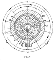
- the angular divisions of the pistons 8, 9 of the two partial circles 10, 11 are different.
- seven pistons 9 of the same cross-section are arranged, three groups G1, G2, G3 each having two or three pistons, in which the angular divisions W1 within the groups G1, G2, G3 are each the same, but between the Groups larger, namely w2.
- This configuration not only ensures a relatively low delivery flow pulsation, but also creates an uneven pulsation, which significantly reduces the running noise of the pump.
- the design according to the invention leads to a relatively small size, because the two pitch circles can be moved as close as possible to one another and thus have a small size radial direction results. Due to the arrangement of the outlet valves 16, 18 of valve rings 51, 52 leads to a small axial size.
- the piston bores 12 can be made shorter for the pistons 8 and the exhaust valves 16, 18 can be arranged in two radial planes, whereby the outlet valve 16 is offset relative to the outlet valve 18 towards the swash plate 14, see distance d.
- the configuration according to the invention thus leads not only to a simple, but also to a small design, and to an axial piston machine with low running noise, which is particularly suitable for means of transportation for people, in particular motor vehicles.
Landscapes
- Engineering & Computer Science (AREA)
- Mechanical Engineering (AREA)
- General Engineering & Computer Science (AREA)
- Reciprocating Pumps (AREA)
- Details Of Reciprocating Pumps (AREA)
- Hydraulic Motors (AREA)
Claims (7)
Applications Claiming Priority (2)
| Application Number | Priority Date | Filing Date | Title |
|---|---|---|---|
| DE19873724970 DE3724970A1 (de) | 1987-07-28 | 1987-07-28 | Axialkolbenmaschine mit unterschiedlichen winkelteilungen fuer die kolben bzw. kolbenbohrungen |
| DE3724970 | 1987-07-28 |
Publications (3)
| Publication Number | Publication Date |
|---|---|
| EP0302208A2 EP0302208A2 (fr) | 1989-02-08 |
| EP0302208A3 EP0302208A3 (en) | 1989-09-06 |
| EP0302208B1 true EP0302208B1 (fr) | 1991-09-25 |
Family
ID=6332530
Family Applications (1)
| Application Number | Title | Priority Date | Filing Date |
|---|---|---|---|
| EP88109854A Expired - Lifetime EP0302208B1 (fr) | 1987-07-28 | 1988-06-21 | Machine axiale à pistons avec partitions angulaires différentes pour les pistons, respectivement les cylindres-pistons |
Country Status (2)
| Country | Link |
|---|---|
| EP (1) | EP0302208B1 (fr) |
| DE (2) | DE3724970A1 (fr) |
Family Cites Families (2)
| Publication number | Priority date | Publication date | Assignee | Title |
|---|---|---|---|---|
| US2238252A (en) * | 1939-01-17 | 1941-04-15 | Anthony William Dellcr | Multiple plunger variable delivery pump |
| FR2031877A5 (fr) * | 1969-02-07 | 1970-11-20 | Bennes Marrel |
-
1987
- 1987-07-28 DE DE19873724970 patent/DE3724970A1/de not_active Withdrawn
-
1988
- 1988-06-21 EP EP88109854A patent/EP0302208B1/fr not_active Expired - Lifetime
- 1988-06-21 DE DE8888109854T patent/DE3865145D1/de not_active Expired - Fee Related
Also Published As
| Publication number | Publication date |
|---|---|
| EP0302208A2 (fr) | 1989-02-08 |
| EP0302208A3 (en) | 1989-09-06 |
| DE3865145D1 (de) | 1991-10-31 |
| DE3724970A1 (de) | 1989-02-09 |
Similar Documents
| Publication | Publication Date | Title |
|---|---|---|
| EP1013928A2 (fr) | Pompe à pistons axiaux à plateau en biais avec disposif d'amortissement de pulsation | |
| DE102008033411B4 (de) | Rückschlagventil | |
| DE2821593C2 (de) | Zweistufenpumpe | |
| DE3018711C2 (de) | Axialkolbenpumpe | |
| WO1994012789A1 (fr) | Soupape comportant peu de composants, en particulier soupape de pression pour pompe a pistons radiaux | |
| DE1426754A1 (de) | Drehkolbenmaschine | |
| DE2527189A1 (de) | Hydraulikpumpe mit taumelscheibe | |
| DE4326323A1 (de) | Taumelscheibenverdichter | |
| DE2852852C2 (de) | Kolbenpumpe, insbesondere Radialkolbenpumpe | |
| DE3440850A1 (de) | Axialkolbenpumpe | |
| DE102017208755A1 (de) | Hydrostatische unterstützungs- und schmierausnehmungen auf valv- segmentslauffläche | |
| DE2634318A1 (de) | Pumpe, vorzugsweise zum dosieren und kalibrieren | |
| EP0302208B1 (fr) | Machine axiale à pistons avec partitions angulaires différentes pour les pistons, respectivement les cylindres-pistons | |
| DE1453435C3 (de) | Hydraulische Radialkolbenmaschine | |
| DE102022202520A1 (de) | Gesonderte Vorkompressionsbaugruppe zur Verwendung mit einer Kolbenmaschine | |
| DE69300999T2 (de) | Innenzahnradpumpe mit regelbarer Liefermenge | |
| DE19945145A1 (de) | Kompressor | |
| DE69100301T2 (de) | Flüssigkeitspumpe mit hin- und hergehendem Kolben. | |
| DE2421160A1 (de) | Pumpe | |
| DE3413867A1 (de) | Axialkolbenpumpe fuer zwei foerderstroeme | |
| EP0301230B1 (fr) | Machine à pistons radiaux ou axiaux avec un aménagement des soupapes comprenant une bague de soupapes | |
| DE10017780B4 (de) | Kolbenmaschine | |
| DE4314217C2 (de) | Radialkolbenpumpe | |
| DE102004029749A1 (de) | Verfahren zur Herstellung eines Drehschiebersteuerventils für eine hydraulische Lenkeinrichtung | |
| DE19961558A1 (de) | Pumpe, insbesondere zur Förderung von Kraftstoff in einem Verbrennungsmotor eines Kraftfahrzeuges |
Legal Events
| Date | Code | Title | Description |
|---|---|---|---|
| PUAI | Public reference made under article 153(3) epc to a published international application that has entered the european phase |
Free format text: ORIGINAL CODE: 0009012 |
|
| AK | Designated contracting states |
Kind code of ref document: A2 Designated state(s): DE FR GB IT SE |
|
| PUAL | Search report despatched |
Free format text: ORIGINAL CODE: 0009013 |
|
| AK | Designated contracting states |
Kind code of ref document: A3 Designated state(s): DE FR GB IT SE |
|
| 17P | Request for examination filed |
Effective date: 19890907 |
|
| 17Q | First examination report despatched |
Effective date: 19900718 |
|
| GRAA | (expected) grant |
Free format text: ORIGINAL CODE: 0009210 |
|
| AK | Designated contracting states |
Kind code of ref document: B1 Designated state(s): DE FR GB IT SE |
|
| ITF | It: translation for a ep patent filed | ||
| REF | Corresponds to: |
Ref document number: 3865145 Country of ref document: DE Date of ref document: 19911031 |
|
| ET | Fr: translation filed | ||
| GBT | Gb: translation of ep patent filed (gb section 77(6)(a)/1977) | ||
| PLBE | No opposition filed within time limit |
Free format text: ORIGINAL CODE: 0009261 |
|
| STAA | Information on the status of an ep patent application or granted ep patent |
Free format text: STATUS: NO OPPOSITION FILED WITHIN TIME LIMIT |
|
| 26N | No opposition filed | ||
| EAL | Se: european patent in force in sweden |
Ref document number: 88109854.5 |
|
| PGFP | Annual fee paid to national office [announced via postgrant information from national office to epo] |
Ref country code: GB Payment date: 19980514 Year of fee payment: 11 |
|
| PGFP | Annual fee paid to national office [announced via postgrant information from national office to epo] |
Ref country code: FR Payment date: 19980518 Year of fee payment: 11 |
|
| PGFP | Annual fee paid to national office [announced via postgrant information from national office to epo] |
Ref country code: DE Payment date: 19980520 Year of fee payment: 11 |
|
| PGFP | Annual fee paid to national office [announced via postgrant information from national office to epo] |
Ref country code: SE Payment date: 19980525 Year of fee payment: 11 |
|
| PG25 | Lapsed in a contracting state [announced via postgrant information from national office to epo] |
Ref country code: GB Free format text: LAPSE BECAUSE OF NON-PAYMENT OF DUE FEES Effective date: 19990621 |
|
| PG25 | Lapsed in a contracting state [announced via postgrant information from national office to epo] |
Ref country code: SE Free format text: THE PATENT HAS BEEN ANNULLED BY A DECISION OF A NATIONAL AUTHORITY Effective date: 19990629 |
|
| PG25 | Lapsed in a contracting state [announced via postgrant information from national office to epo] |
Ref country code: FR Free format text: THE PATENT HAS BEEN ANNULLED BY A DECISION OF A NATIONAL AUTHORITY Effective date: 19990630 |
|
| GBPC | Gb: european patent ceased through non-payment of renewal fee |
Effective date: 19990621 |
|
| EUG | Se: european patent has lapsed |
Ref document number: 88109854.5 |
|
| PG25 | Lapsed in a contracting state [announced via postgrant information from national office to epo] |
Ref country code: DE Free format text: LAPSE BECAUSE OF NON-PAYMENT OF DUE FEES Effective date: 20000503 |
|
| REG | Reference to a national code |
Ref country code: FR Ref legal event code: ST |
|
| PG25 | Lapsed in a contracting state [announced via postgrant information from national office to epo] |
Ref country code: IT Free format text: LAPSE BECAUSE OF NON-PAYMENT OF DUE FEES Effective date: 20050621 |