EP0302256A2 - Roller chain for a printing press web-threading device - Google Patents
Roller chain for a printing press web-threading device Download PDFInfo
- Publication number
- EP0302256A2 EP0302256A2 EP88110924A EP88110924A EP0302256A2 EP 0302256 A2 EP0302256 A2 EP 0302256A2 EP 88110924 A EP88110924 A EP 88110924A EP 88110924 A EP88110924 A EP 88110924A EP 0302256 A2 EP0302256 A2 EP 0302256A2
- Authority
- EP
- European Patent Office
- Prior art keywords
- roller chain
- rollers
- chain according
- flexible cable
- flexible
- Prior art date
- Legal status (The legal status is an assumption and is not a legal conclusion. Google has not performed a legal analysis and makes no representation as to the accuracy of the status listed.)
- Granted
Links
- 125000006850 spacer group Chemical group 0.000 claims abstract description 13
- 229910000831 Steel Inorganic materials 0.000 claims 1
- 230000006835 compression Effects 0.000 claims 1
- 238000007906 compression Methods 0.000 claims 1
- 239000010959 steel Substances 0.000 claims 1
- 238000004519 manufacturing process Methods 0.000 description 1
Images
Classifications
-
- B—PERFORMING OPERATIONS; TRANSPORTING
- B41—PRINTING; LINING MACHINES; TYPEWRITERS; STAMPS
- B41F—PRINTING MACHINES OR PRESSES
- B41F13/00—Common details of rotary presses or machines
- B41F13/02—Conveying or guiding webs through presses or machines
- B41F13/03—Threading webs into printing machines
-
- F—MECHANICAL ENGINEERING; LIGHTING; HEATING; WEAPONS; BLASTING
- F16—ENGINEERING ELEMENTS AND UNITS; GENERAL MEASURES FOR PRODUCING AND MAINTAINING EFFECTIVE FUNCTIONING OF MACHINES OR INSTALLATIONS; THERMAL INSULATION IN GENERAL
- F16G—BELTS, CABLES, OR ROPES, PREDOMINANTLY USED FOR DRIVING PURPOSES; CHAINS; FITTINGS PREDOMINANTLY USED THEREFOR
- F16G13/00—Chains
- F16G13/02—Driving-chains
-
- F—MECHANICAL ENGINEERING; LIGHTING; HEATING; WEAPONS; BLASTING
- F16—ENGINEERING ELEMENTS AND UNITS; GENERAL MEASURES FOR PRODUCING AND MAINTAINING EFFECTIVE FUNCTIONING OF MACHINES OR INSTALLATIONS; THERMAL INSULATION IN GENERAL
- F16G—BELTS, CABLES, OR ROPES, PREDOMINANTLY USED FOR DRIVING PURPOSES; CHAINS; FITTINGS PREDOMINANTLY USED THEREFOR
- F16G3/00—Belt fastenings, e.g. for conveyor belts
- F16G3/02—Belt fastenings, e.g. for conveyor belts with series of eyes or the like, interposed and linked by a pin to form a hinge
Definitions
- the invention relates to a roller chain for a paper web feed device according to the preamble of patent claim 1.
- the invention has for its object to develop a roller chain of the type mentioned so that it is movable along a spatially curved guide.
- each link in the roller chain has a pin 1, a roller 2 mounted centrally on it in the axial direction, and a locking ring 3. Between two adjacent bolts 1, two flexible ropes 4 and 5 and two spacer elements 6 are arranged, through which the ropes 4 and 5 are passed.
- a bolt 1 is shown enlarged. It consists of a thrust collar 7, a bearing surface 8 for the roller 2, an annular groove 9 for receiving the locking ring 3 and an end piece 10 corresponding in diameter to the bearing surface 8.
- the thrust collar 7 and the end piece 10 have bores 11 which penetrate the longitudinal axis of the bolt radially, whose diameter allows the cables 4 and 5 to pass through.
- Two adjacent bolts 1 are held by the spacer elements 6, which are designed as coil springs wound in a block, at a distance from one another which corresponds to the pitch t of the links of the roller chain and the tooth pitch of a chain wheel 12 (see FIG. 1).
- the ropes 4, 5 are connected to each bolt 1 during the manufacture of the roller chain.
- a thread 14 is attached to one of the bolts 1 at its axially elongated end piece 13, which carries for fastening a holding device, not shown, which serves to connect the end of the paper web to be drawn in.
- a guide 15 matching the pull-in element described above is shown together with this in cross section.
- a square profi le slotted on one side serves as a guide, the inner wall distance of which enables the rollers 2 to be easily rolled off while at the same time tightly guiding them.
- the elongated end piece 13 carrying the holding device is guided laterally out of the guide 15 through the slot.
- Not shown on the underside of the guides 15 allow, at certain intervals, the engagement of a sprocket 12 which introduces the transport forces into the roller chain into the spaces between the bolts 1.
- a bolt 16 has bearing surfaces 18 for rollers 19 arranged thereon on both sides of its central part 17 with a larger cross section, and ring grooves 20 axially outwardly thereafter for receiving retaining rings 21.
- the individual bolts 16 are connected by a cable 22, which passes through bores 23 of each bolt 1, which run radially in the central part 17 and is connected to them by squeezing, and are kept at a distance by spacer elements 24 surrounding the cable 22.
- the sprocket 25 indicated in FIGS. 5 and 7 for driving this pull-in element has a recess 26 on the end faces of its teeth, as shown in FIG.
- a guide 28 matching the pull-in element described above is shown together with this in cross section.
- a square profile, slotted on one side, serves as a guide, the inner wall spacing of which enables the rollers 19 to roll off easily while at the same time tightly guiding them.
- the elongated end piece 29 of a bolt 16, which carries a holding device and is shown in FIG. 6, is guided laterally out of the guide through the slot.
- Recesses, not shown, on the underside of the guides 28 enable the sprocket 25, which introduces the transport forces into the roller chain, to engage at certain intervals.
Landscapes
- Engineering & Computer Science (AREA)
- General Engineering & Computer Science (AREA)
- Mechanical Engineering (AREA)
- Rotary Presses (AREA)
- Replacement Of Web Rolls (AREA)
- Registering, Tensioning, Guiding Webs, And Rollers Therefor (AREA)
- Devices For Conveying Motion By Means Of Endless Flexible Members (AREA)
Abstract
Je zwei benachbarte, Laufrollen (2) tragende Bolzen 1 sind durch mindestens ein flexibles Seil (4, 5) verbunden und werden durch mindestens ein bei Druckbeanspruchung inkompressibles, flexibles Distanzelement (6) im vorgeschriebenen Teilungsabstand t gehalten.Two adjacent bolts 1 carrying rollers (2) are connected by at least one flexible cable (4, 5) and are held in the prescribed pitch t by at least one flexible spacer element (6) that is incompressible under pressure.
Durch ihre hohe Biegsamkeit und ihre Verwindbarkeit um die Längsachse ist die Rollenkette auch für stark räumlich gekrümmte Führungen, wie die Herumführung um Wendestangen bei Rollen-Rotationsdruckmaschinen geeignet. 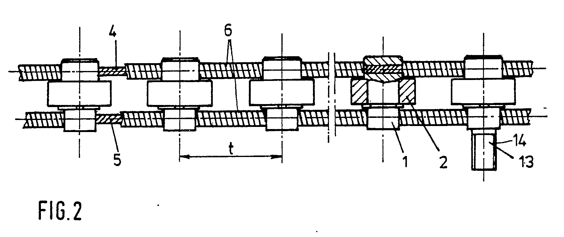
Description
Die Erfindung betrifft eine Rollenkette für eine Papierbahneinzugsvorrichtung gemäß dem Oberbegriff des Patentanspruchs 1.The invention relates to a roller chain for a paper web feed device according to the preamble of
Aus der DE-PS 22 41 127 ist eine Papierbahn-Einzugsvorrichtung einer Rollen-Rotationsdruckmaschine mit einer entlang einer Führung verfahrbaren Rollenkette bekannt. Die auf Bolzen sitzenden Rollen sind dabei durch Laschen miteinander verbunden. Aufgrund der relativ steifen Laschen ist eine Biegung dieser Kette nur in einer Ebene möglich.From DE-PS 22 41 127 a paper web feeding device of a web-fed rotary printing press with a roller chain that can be moved along a guide is known. The casters on bolts are connected to each other by tabs. Due to the relatively stiff plates, this chain can only be bent in one plane.
Der Erfindung liegt die Aufgabe zugrunde, eine Rollenkette der eingangs genannten Gattung so weiterzubilden, daß diese entlang einer räumlich gekrümmten Führung beweglich ist.The invention has for its object to develop a roller chain of the type mentioned so that it is movable along a spatially curved guide.
Diese Aufgabe wird durch die Merkmale im Kennzeichen des Patentanspruchs 1 gelöst. Durch die Aufteilung der bei der herkömmlichen Rollenkette durch die Laschen übertragenen Zug- und Druckkräfte auf ein flexibles Seil und ebenso flexible Distanzelemente wird ein biegsames und zusätzlich um seine Längsachse verwindbares Einzugselement geschaffen, das bei allen räumlich gekrümmten Führungen, wie beispielsweise der Herumführung um Wendestangen, anwendbar ist.This object is achieved by the features in the characterizing part of
Nachfolgend sind Ausführungsbeispiele der Erfindung anhand der Zeichnungen erklärt. Dabei zeigt
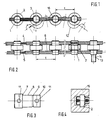
- Fig. 1 eine erfindungsgemäße Rollenkette in Seitenansicht,
- Fig. 2 eine Draufsicht zur Fig. 1.
- Fig. 3 eine vergrößerte Einzelheit aus Fig. 1 und 2,
- Fig. 4 eine Rollenkette gemäß Fig. 1 und 2 mit einer geeigneten Führung im Querschnitt,
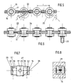
- Fig. 5 eine Variante zur Fig. 1,
- Fig. 6 eine Draufsicht zur Fig. 5,
- Fig. 7 eine vergrößerte Einzelheit aus Fig. 5 und 6
- Fig. 8 einen Querschnitt durch die Variante nach Fig. 5 mit einer geeigneten Führung.
- 1 is a roller chain according to the invention in side view,
- FIG. 2 is a top view of FIG. 1.
- 3 shows an enlarged detail from FIGS. 1 and 2,
- 4 shows a roller chain according to FIGS. 1 and 2 with a suitable guide in cross section,
- 5 shows a variant of FIG. 1,
- 6 is a plan view of FIG. 5,
- 7 shows an enlarged detail from FIGS. 5 and 6
- Fig. 8 shows a cross section through the variant of FIG. 5 with a suitable guide.
In Fig. 1 und 2 sind mehrere Glieder einer Rollenkette für eine Papierbahneinzugsvorrichtung einer Druckmaschine dargestellt. Jedes Glied der Rollenkette weist einen Bolzen 1, eine auf diesem in axialer Richtung mittig gelagerte Laufrolle 2 sowie einen Sicherungsring 3 auf. Zwischen zwei benachbarten Bolzen 1 sind jeweils zwei flexible Seile 4 und 5 und zwei Distanzelemente 6 angeordnet, durch die die Seile 4 und 5 hindurchgeführt sind.1 and 2 show several links of a roller chain for a paper web feed device of a printing press. Each link in the roller chain has a
In Fig. 3 ist ein Bolzen 1 vergrößert dargestellt. Er besteht aus einem Anlaufbund 7, einer Lagerfläche 8 für die Laufrolle 2, einer Ringnut 9 zur Aufnahme des Sicherungsrings 3 sowie einem im Durchmesser der Lagerfläche 8 entsprechenden Endstück 10. Der Anlaufbund 7 und das Endstück 10 weisen die Bolzenlängsachse radial durchdringende Bohrungen 11 auf, deren Durchmesser eine Hindurchführung der Seile 4 und 5 gestattet. Je zwei benachbarte Bolzen 1 werden durch die Distanzelemente 6, die als im Block gewickelte Spiralfedern ausgeführt sind, in einem Abstand voneinander gehalten, der dem Teilungsabstand t der Glieder der Rollenkette wie auch der Zahnteilung eines Kettenrades 12 entspricht (siehe Fig. 1). Die Seile 4, 5 werden bei der Fertigung der Rollenkette mit jedem Bolzen 1 verbunden. Dies kann vorteilhaft nach Durchziehen des Seiles durch Quetschen des Bolzens 1 im Bereich der Bohrungen 11 erreicht werden. Die Seile 4 und 5 übertragen somit innerhalb des Einzugselements Zugkräfte; die bei Druckbeanspruchung nicht komprimierbaren Distanzelemente übertragen die auftretenden Druckkräfte.In Fig. 3, a
In Fig. 2 ist an einem der Bolzen 1 an dessen axial verlängertem Endstück 13 ein Gewinde 14 angebracht, das zum Befestigen einer nicht dargestellten, zum Anschluß des einzuziehenden Papierbahnendes dienenden Haltevorrichtungen trägt.In Fig. 2, a
In Fig. 4 ist eine zum vorstehend beschriebenen Einzugselement passende Führung 15 gemeinsam mit diesem im Querschnitt dargestellt. Als Führung dient ein einseitig geschlitzes Vierkantprofitl, dessen innerer Wandabstand ein leichtes Abrollen der Laufrollen 2 bei gleichzeitiger enger Führung derselben ermöglicht. Durch den Schlitz ist das die Haltevorrichtung tragende verlängerte Endstück 13 seitlich aus der Führung 15 herausgeführt. Nicht dargestellte Asnehmungen an der Unterseite der Führungen 15 ermöglichen in bestimmten Abständen den Eingriff eines die Transportkräfte in die Rollenkette einleitenden Kettenrades 12 in die Zwischenräume zwischen den Bolzen 1.In Fig. 4, a
Bei einer in den Fig. 5 bis 8 dargestellten Variante weist ein Bolzen 16 beiderseits seines querschnittsstärkeren Mittelteils 17 Lagerflächen 18 für darauf angeordnete Laufrollen 19, sowie daran axial nach außen anschließend Ringnuten 20 für die Aufnahme von Sicherungsringen 21 auf. Die einzelnen Bolzen 16 stehen durch ein Seil 22, welches durch im Mittelteil 17 radial verlaufende Bohrungen 23 eines jeden Bolzens 1 hindurchgeführt und mit diesen durch Quetschen verbunden ist, in Verbindung und werden durch das Seil 22 umgebende Distanzelemente 24 auf Abstand gehalten. Das in Fig. 5 und 7 angedeutete Kettenrad 25 für den Antrieb dieses Einzugselements weist an den Stirnseiten seiner Zähne - wie in Fig. 7 dargestellt - eine Eindrehung 26 auf, so daß die von dieser gebildeten beiden Zahnspitzen 27 im Bereich einer Antriebsstation die Distanzelemente 24 seitlich umgeben. Statt der Eindrehung 26 wäre auch eine Verwendung von zwei schmalen Kettenrädern möglich, die durch einen zwischen ihnen angeordneten Distanzring in einem Abstand voneinander gehalten werden, der etwas größer ist, als der Durchmesser eines Distanzelementes 24. Die vorstehend beschriebene Variante hat gegenüber der ersten Ausführungsform den Vorteil einer noch leichteren Verwindbarkeit.In a variant shown in FIGS. 5 to 8, a
In Fig. 8 ist eine zum vorstehend beschriebenen Einzugselement passende Führung 28 gemeinsam mit diesem im Querschnitt dargestellt. Als Führung dient ein einseitig geschlitztes Vierkantprofil, dessen innerer Wandabstand ein leichtes Abrollen der Laufrollen 19 bei gleichzeitig enger Führung derselben ermöglicht. Durch den Schlitz ist das in Fig. 6 dargestellte, eine Haltevorrichtung tragende verlängerte Endstück 29 eines Bolzens 16 seitlich aus der Führung herausgeführt. Nicht dargestellte Ausnehmungen an der Unterseite der Führungen 28 ermöglichen in bestimmten Abständen den Eingriff des die Transportkräfte in die Rollenkette einleitenden Kettenrades 25.In Fig. 8, a
Claims (7)
Applications Claiming Priority (2)
| Application Number | Priority Date | Filing Date | Title |
|---|---|---|---|
| DE3725634 | 1987-08-03 | ||
| DE3725634A DE3725634A1 (en) | 1987-08-03 | 1987-08-03 | ROLLER CHAIN FOR A PAPER RAIL FEEDER OF A PRINTING MACHINE |
Publications (3)
| Publication Number | Publication Date |
|---|---|
| EP0302256A2 true EP0302256A2 (en) | 1989-02-08 |
| EP0302256A3 EP0302256A3 (en) | 1990-03-21 |
| EP0302256B1 EP0302256B1 (en) | 1993-01-27 |
Family
ID=6332922
Family Applications (1)
| Application Number | Title | Priority Date | Filing Date |
|---|---|---|---|
| EP88110924A Expired - Lifetime EP0302256B1 (en) | 1987-08-03 | 1988-07-08 | Roller chain for a printing press web-threading device |
Country Status (5)
| Country | Link |
|---|---|
| US (1) | US4819557A (en) |
| EP (1) | EP0302256B1 (en) |
| JP (1) | JP2730580B2 (en) |
| CA (1) | CA1279337C (en) |
| DE (2) | DE3725634A1 (en) |
Cited By (2)
| Publication number | Priority date | Publication date | Assignee | Title |
|---|---|---|---|---|
| EP0870610A1 (en) * | 1997-04-10 | 1998-10-14 | Heidelberger Druckmaschinen Aktiengesellschaft | Threading device for a rotary printing machine |
| WO2005092614A3 (en) * | 2004-03-26 | 2006-02-09 | Koenig & Bauer Ag | Devices and method for drawing at least one web of material or at least one web strand into a folding apparatus |
Families Citing this family (12)
| Publication number | Priority date | Publication date | Assignee | Title |
|---|---|---|---|---|
| CA2025552C (en) * | 1989-09-20 | 1993-12-21 | Kunio Suzuki | Paper web threading apparatus for rotary printing press |
| JPH0657578B2 (en) * | 1990-12-13 | 1994-08-03 | 株式会社東京機械製作所 | Paper threading device |
| US5249373A (en) * | 1991-01-29 | 1993-10-05 | W. R. Grace & Co.-Conn. | Web threading system |
| DE4110668C1 (en) * | 1991-04-03 | 1992-05-27 | Koenig & Bauer Ag, 8700 Wuerzburg, De | |
| DE4202713C2 (en) * | 1992-01-31 | 1993-11-04 | Koenig & Bauer Ag | GUIDE TO INPUT A MATERIAL RAIL INTO A ROLL ROTARY PRINTING MACHINE |
| DE4322929C1 (en) * | 1993-07-09 | 1995-02-16 | Koenig & Bauer Ag | Roller chain |
| US6110095A (en) * | 1997-04-18 | 2000-08-29 | United Container Machinery Inc. | Apparatus for heating corrugated paperboard |
| DE19758468A1 (en) * | 1997-05-02 | 1998-11-12 | Koenig & Bauer Albert Ag | Variable-length guide rail piece |
| DE50307175D1 (en) * | 2002-05-28 | 2007-06-14 | Schott Ag | DEVICE FOR BROKEN PRESSING OF GLASS BODIES |
| DE10248522A1 (en) * | 2002-10-17 | 2004-04-29 | Man Roland Druckmaschinen Ag | Roller chain for a paper pull-in mechanism in a printing machine comprises rollers which are distanced from one another by chain plates also serving to form roller groups |
| CN104085176B (en) * | 2014-07-26 | 2016-04-20 | 帝龙新材料(临沂)有限公司 | For the rolling-up mechanism of gravure printing machine |
| FR3071893B1 (en) * | 2017-09-29 | 2019-09-20 | Total Raffinage Chimie | SUPPORT DEVICE FOR AN ENABLING CHAIN WITH SUPPORT ERGOTS. |
Family Cites Families (17)
| Publication number | Priority date | Publication date | Assignee | Title |
|---|---|---|---|---|
| DE116402C (en) * | 1900-01-01 | |||
| FR405845A (en) * | 1908-11-24 | 1910-01-14 | Eugene Robergel | Chain for transmission by pinions |
| US2944345A (en) * | 1958-01-30 | 1960-07-12 | Time Inc | Drive mechanism for web threading apparatus |
| DE1137396B (en) * | 1961-02-27 | 1962-09-27 | Karl Stumpf K G | Endlessly circulating conveyor |
| US3587461A (en) * | 1968-07-08 | 1971-06-28 | Wood Industries Inc | Web threading device in rotary printing machines |
| JPS4836325B1 (en) * | 1970-04-30 | 1973-11-02 | ||
| DE2402768C2 (en) * | 1974-01-22 | 1978-04-20 | Maschinenfabrik Augsburg-Nuernberg Ag, 8900 Augsburg | Device for drawing in webs of material in rotary printing machines |
| DE2519662C2 (en) * | 1974-05-06 | 1982-09-09 | Maschinenfabrik Wifag, 3001 Bern | Device for drawing in the material web in rotary printing machines |
| CH615132A5 (en) * | 1976-05-14 | 1980-01-15 | Rigert Cesar | Conveying installation |
| DE2657789A1 (en) * | 1976-12-21 | 1978-06-29 | Maschf Augsburg Nuernberg Ag | DEVICE FOR PULLING A PAPER TRAIL INTO THE FOLDER OF A ROTARY PRINTING MACHINE |
| DE8011068U1 (en) * | 1980-04-23 | 1980-07-17 | M.A.N.-Roland Druckmaschinen Ag, 6050 Offenbach | FEED DEVICE FOR ROLL ROTARY PRINTING MACHINES |
| DE3018740C2 (en) * | 1980-05-16 | 1986-02-06 | M.A.N.- Roland Druckmaschinen AG, 6050 Offenbach | Device for drawing in webs of material in rotary printing machines |
| DE3048797C2 (en) * | 1980-12-23 | 1982-09-23 | M.A.N.- Roland Druckmaschinen AG, 6050 Offenbach | Roller chain, in particular for pulling in webs of material in rotary roller printing machines |
| US4480801A (en) * | 1982-05-13 | 1984-11-06 | Motter Printing Press Co. | Webbing system |
| DE3309121C1 (en) * | 1983-03-15 | 1984-08-16 | M.A.N.- Roland Druckmaschinen AG, 6050 Offenbach | Device for attaching a material web to the driver of a web feed device |
| JPS6176368A (en) * | 1984-09-25 | 1986-04-18 | Mitsubishi Heavy Ind Ltd | Paper-passing device for printing press |
| US4958850A (en) * | 1988-03-03 | 1990-09-25 | Toyota Jidosha Kabushiki Kaisha | Hydraulic circuit system for a vehicle height control device |
-
1987
- 1987-08-03 DE DE3725634A patent/DE3725634A1/en active Granted
-
1988
- 1988-07-08 EP EP88110924A patent/EP0302256B1/en not_active Expired - Lifetime
- 1988-07-08 DE DE8888110924T patent/DE3877850D1/en not_active Expired - Fee Related
- 1988-07-13 US US07/218,806 patent/US4819557A/en not_active Expired - Fee Related
- 1988-07-28 CA CA000573348A patent/CA1279337C/en not_active Expired - Lifetime
- 1988-08-01 JP JP63190761A patent/JP2730580B2/en not_active Expired - Lifetime
Cited By (5)
| Publication number | Priority date | Publication date | Assignee | Title |
|---|---|---|---|---|
| EP0870610A1 (en) * | 1997-04-10 | 1998-10-14 | Heidelberger Druckmaschinen Aktiengesellschaft | Threading device for a rotary printing machine |
| FR2761924A1 (en) * | 1997-04-10 | 1998-10-16 | Heidelberger Druckmasch Ag | DEVICE FOR INSERTING PAPER STRIPS IN A ROTARY PRINTING MACHINE |
| US5967036A (en) * | 1997-04-10 | 1999-10-19 | Heidelberger Druckmaschinen Ag | Web infeed device for rotary printing presses |
| WO2005092614A3 (en) * | 2004-03-26 | 2006-02-09 | Koenig & Bauer Ag | Devices and method for drawing at least one web of material or at least one web strand into a folding apparatus |
| US7387601B2 (en) | 2004-03-26 | 2008-06-17 | Koenig & Bauer Aktiengesellschaft | Devices and methods for drawing at least one web of material or at least one web strand into a folding apparatus |
Also Published As
| Publication number | Publication date |
|---|---|
| JP2730580B2 (en) | 1998-03-25 |
| DE3725634A1 (en) | 1989-02-16 |
| EP0302256B1 (en) | 1993-01-27 |
| US4819557A (en) | 1989-04-11 |
| JPH01157849A (en) | 1989-06-21 |
| DE3877850D1 (en) | 1993-03-11 |
| CA1279337C (en) | 1991-01-22 |
| EP0302256A3 (en) | 1990-03-21 |
| DE3725634C2 (en) | 1989-08-24 |
Similar Documents
| Publication | Publication Date | Title |
|---|---|---|
| DE3432548C2 (en) | Guide device for roller bars in a continuously operating press | |
| DE3913991C2 (en) | Continuously working press | |
| DE2246975C2 (en) | Conveyor roller for belt conveyors or belt-like materials | |
| EP0302256A2 (en) | Roller chain for a printing press web-threading device | |
| DE1685829B2 (en) | Parallel wire bundle and device for its manufacture | |
| EP0138745B1 (en) | Driving pulley for a slat conveyor | |
| EP0507198B1 (en) | Roller chain for the web threading device of a rotary web printing press | |
| EP0360033A1 (en) | Cable traction device | |
| DE3633380A1 (en) | TENSIONING DEVICE FOR CONNECTING TWO FLANGES | |
| DE3123291C2 (en) | Roller bed on a continuously operating press | |
| DE60004249T2 (en) | AUXILIARY CHAIN FOR THE DRAWING SYSTEM OF A DRAWING DEVICE | |
| DE3443930A1 (en) | Apparatus for the continuous bending of spirals | |
| DE4034222C2 (en) | Belt connection for steel cable conveyor belts | |
| DE1750972A1 (en) | Transmission chain | |
| DE2201548C3 (en) | Cable winch for unlimited cable passage | |
| DE2165973B1 (en) | DEVICE FOR PULLING RIBS ON SEVERAL TUBES, FIXED ADDITIONALLY | |
| EP1316381A1 (en) | Wire-feeding device for a wire welding installation | |
| EP1385647B1 (en) | Chain drawing machine for continuously drawing drawn items | |
| DE2135829A1 (en) | Belt drive for the transmission of larger torques | |
| DE4123819A1 (en) | Load lifting appliance using cables - which are wound around grooves in two meshing toothed wheels | |
| DE2166267C2 (en) | Roller chain | |
| DE3404505C2 (en) | Length compensation between two ropes in one rope drive | |
| DE3022691A1 (en) | Radiussing sharp edges of strip material - uses profilated rollers pressurised at right angles to and parallel to plane of strip | |
| DE3700592C2 (en) | Continuously working press | |
| DE3229801C2 (en) | Rope brake for the automatic braking of a rope |
Legal Events
| Date | Code | Title | Description |
|---|---|---|---|
| PUAI | Public reference made under article 153(3) epc to a published international application that has entered the european phase |
Free format text: ORIGINAL CODE: 0009012 |
|
| AK | Designated contracting states |
Kind code of ref document: A2 Designated state(s): CH DE FR GB IT LI SE |
|
| PUAL | Search report despatched |
Free format text: ORIGINAL CODE: 0009013 |
|
| AK | Designated contracting states |
Kind code of ref document: A3 Designated state(s): CH DE FR GB IT LI SE |
|
| 17P | Request for examination filed |
Effective date: 19900210 |
|
| 17Q | First examination report despatched |
Effective date: 19910719 |
|
| ITF | It: translation for a ep patent filed | ||
| GRAA | (expected) grant |
Free format text: ORIGINAL CODE: 0009210 |
|
| AK | Designated contracting states |
Kind code of ref document: B1 Designated state(s): CH DE FR GB IT LI SE |
|
| REF | Corresponds to: |
Ref document number: 3877850 Country of ref document: DE Date of ref document: 19930311 |
|
| GBT | Gb: translation of ep patent filed (gb section 77(6)(a)/1977) |
Effective date: 19930330 |
|
| ET | Fr: translation filed | ||
| PLBE | No opposition filed within time limit |
Free format text: ORIGINAL CODE: 0009261 |
|
| STAA | Information on the status of an ep patent application or granted ep patent |
Free format text: STATUS: NO OPPOSITION FILED WITHIN TIME LIMIT |
|
| 26N | No opposition filed | ||
| EAL | Se: european patent in force in sweden |
Ref document number: 88110924.3 |
|
| PGFP | Annual fee paid to national office [announced via postgrant information from national office to epo] |
Ref country code: GB Payment date: 19980612 Year of fee payment: 11 |
|
| PGFP | Annual fee paid to national office [announced via postgrant information from national office to epo] |
Ref country code: SE Payment date: 19980624 Year of fee payment: 11 |
|
| PGFP | Annual fee paid to national office [announced via postgrant information from national office to epo] |
Ref country code: FR Payment date: 19980629 Year of fee payment: 11 |
|
| PGFP | Annual fee paid to national office [announced via postgrant information from national office to epo] |
Ref country code: DE Payment date: 19980630 Year of fee payment: 11 |
|
| PGFP | Annual fee paid to national office [announced via postgrant information from national office to epo] |
Ref country code: CH Payment date: 19980701 Year of fee payment: 11 |
|
| PG25 | Lapsed in a contracting state [announced via postgrant information from national office to epo] |
Ref country code: GB Free format text: LAPSE BECAUSE OF NON-PAYMENT OF DUE FEES Effective date: 19990708 |
|
| PG25 | Lapsed in a contracting state [announced via postgrant information from national office to epo] |
Ref country code: SE Free format text: THE PATENT HAS BEEN ANNULLED BY A DECISION OF A NATIONAL AUTHORITY Effective date: 19990730 |
|
| PG25 | Lapsed in a contracting state [announced via postgrant information from national office to epo] |
Ref country code: LI Free format text: LAPSE BECAUSE OF NON-PAYMENT OF DUE FEES Effective date: 19990731 Ref country code: FR Free format text: THE PATENT HAS BEEN ANNULLED BY A DECISION OF A NATIONAL AUTHORITY Effective date: 19990731 Ref country code: CH Free format text: LAPSE BECAUSE OF NON-PAYMENT OF DUE FEES Effective date: 19990731 |
|
| GBPC | Gb: european patent ceased through non-payment of renewal fee |
Effective date: 19990708 |
|
| REG | Reference to a national code |
Ref country code: CH Ref legal event code: PL |
|
| EUG | Se: european patent has lapsed |
Ref document number: 88110924.3 |
|
| PG25 | Lapsed in a contracting state [announced via postgrant information from national office to epo] |
Ref country code: DE Free format text: LAPSE BECAUSE OF NON-PAYMENT OF DUE FEES Effective date: 20000503 |
|
| REG | Reference to a national code |
Ref country code: FR Ref legal event code: ST |
|
| PG25 | Lapsed in a contracting state [announced via postgrant information from national office to epo] |
Ref country code: IT Free format text: LAPSE BECAUSE OF NON-PAYMENT OF DUE FEES;WARNING: LAPSES OF ITALIAN PATENTS WITH EFFECTIVE DATE BEFORE 2007 MAY HAVE OCCURRED AT ANY TIME BEFORE 2007. THE CORRECT EFFECTIVE DATE MAY BE DIFFERENT FROM THE ONE RECORDED. Effective date: 20050708 |