EP0302306A2 - Dampf-Luftrotations-Sterilisierungssystem und Verfahren - Google Patents
Dampf-Luftrotations-Sterilisierungssystem und Verfahren Download PDFInfo
- Publication number
- EP0302306A2 EP0302306A2 EP88111687A EP88111687A EP0302306A2 EP 0302306 A2 EP0302306 A2 EP 0302306A2 EP 88111687 A EP88111687 A EP 88111687A EP 88111687 A EP88111687 A EP 88111687A EP 0302306 A2 EP0302306 A2 EP 0302306A2
- Authority
- EP
- European Patent Office
- Prior art keywords
- steam
- pressure
- containers
- air
- pressure vessel
- Prior art date
- Legal status (The legal status is an assumption and is not a legal conclusion. Google has not performed a legal analysis and makes no representation as to the accuracy of the status listed.)
- Withdrawn
Links
Images


Classifications
-
- A—HUMAN NECESSITIES
- A23—FOODS OR FOODSTUFFS; TREATMENT THEREOF, NOT COVERED BY OTHER CLASSES
- A23B—PRESERVATION OF FOODS, FOODSTUFFS OR NON-ALCOHOLIC BEVERAGES; CHEMICAL RIPENING OF FRUIT OR VEGETABLES
- A23B2/00—Preservation of foods or foodstuffs, in general
- A23B2/20—Preservation of foods or foodstuffs, in general by heating materials in packages which are progressively transported, continuously or stepwise, through the apparatus
- A23B2/25—Preservation of foods or foodstuffs, in general by heating materials in packages which are progressively transported, continuously or stepwise, through the apparatus with packages transported along a helical path
-
- A—HUMAN NECESSITIES
- A23—FOODS OR FOODSTUFFS; TREATMENT THEREOF, NOT COVERED BY OTHER CLASSES
- A23B—PRESERVATION OF FOODS, FOODSTUFFS OR NON-ALCOHOLIC BEVERAGES; CHEMICAL RIPENING OF FRUIT OR VEGETABLES
- A23B2/00—Preservation of foods or foodstuffs, in general
- A23B2/003—Control or safety devices for sterilisation or pasteurisation systems
Definitions
- the present invention pertains to sterilizing systems and methods and more particularly relates to a system of and method for processing hermetically sealed plastic containers using a steam-air mixture in a reel and spiral sterilizing apparatus for preventing container deformation and improving the container appearance when sterilizing a product within the container such as food products, liquids and pharmaceuticals.
- Assignees' Wilbur Patent 2,536,115 discloses such a system wherein the main portion of the steam and air enters a pressure preheater at different locations.
- Assignees' Wilbur Patent 2,536,116 discloses a similar steam-air pressure cooker wherein the interior of the cooker is divided into three longitudinally spaced zones by baffles with the steam and the air being separately directed into each zone. Controls maintain a temperature in the inlet zone of about 225° F. and maintain a temperature of about 235° F. in the outlet zone with an intermediate zone being at an intermediate temperature. A small portion of the steam entering the cooking chamber, and a small portion of the steam-air mixture in each zone are recirculated through arcuate conduits and are then directed into the associated zones by steam injectors which are intended to maintain the steam-air mixture properly mixed.
- the steam-air rotary sterilizing system and method of the present invention is provided for sterilizing products hermetically sealed in containers herein illustrated as plastic containers.
- a steam-air mixture is used in order to prevent the plastic containers from deforming due to excessive internal pressure in the containers. Saturated steam alone causes the plastic containers to grow and otherwise deform when the internal pressure in the containers becomes greater than that acting on the external surfaces of the containers.
- the steam-air mixture In order to be commercially acceptable, the steam-air mixture must be sufficiently mixed to prevent cold areas in the mixture which may provide insufficient heat to sterilize the contents of the containers.
- At least the major portion of the air in the steam-air mixture is first introduced into a steam log extending longitudinally of the sterilizer thereby assuring a proper steam-air mixture.
- This well mixed steam-air is then directed into the sterilizer through a plurality of longitudinally spaced conduits. Since the containers entering the inlet end portion of the sterilizer have a lower internal pressure and are cooler than those in the outlet end portion, condensation of steam in the inlet end portion is much greater than that in the outlet end portion.
- an additional controlled source of steam may be directed only into the inlet end portion to prevent a lower temperature from occurring in the steam-air mixture at the inlet end. This addition of steam increases the rate of sterilization and thus makes possible an increased rate of flow of containers through the sterilizing system without any detrimental effect to the containers because the internal pressure of the containers is low when in the inlet end of the sterilizer.
- a split range air pressure controller for directing air into the sterilizer when the sterilizer pressure is low; and to bleed a portion of the steam-air mixture out of the sterilizer when the pressure is high.
- a steam temperature controller maintains the temperature therein at the desired level.
- Additional embodiments of the invention use separate steam logs and air logs for directing steam and air into the sterilizer through a plurality of conduits spaced longitudinally of the sterilizer for substantially the full length of the sterilizer.
- Orifices in the steam conduits may be adjusted to progressively direct greater amounts of steam into the sterilizer from the feed end to the discharge end thereof, while orifices in the air conduits may be adjusted to progressively direct lesser amounts of air into the sterilizer from the feed end to the discharge end thereof, thereby compensating for the faster steam condensation at the feed end of the sterilizer.
- the basic components of the sterilizing system 20 (Figs. 1-4) of the present invention may include an atmospheric preheater 22 having water therein at about 140° - 212° F. (Fahrenheit); a pressure preheater 24 having a steam-air mixture therein at about 225 - 235° F.; a sterilizer 26 having a steam-air mixture therein at about 255° - 265° F.; a pressure cooler 28 having water circulating therein at about 120 - 180° F. and subjected to an overriding air pressure; and an atmospheric cooler 30 having cooling water circulating therein at about 70° - 120° F.
- an atmospheric preheater 22 having water therein at about 140° - 212° F. (Fahrenheit); a pressure preheater 24 having a steam-air mixture therein at about 225 - 235° F.; a sterilizer 26 having a steam-air mixture therein at about 255° - 265° F.; a pressure cooler 28 having water
- plastic containers as illustrated includes a plastic body and a metal wear resistant closure C′, it will be understood that many other types of plastic containers may be processed in the sterilizing system 20.
- the containers may include a plastic body sealed by a plastic closure, or may be made in the form of a one piece plastic container.
- plastic containers have been illustrated and will be referred to throughout the specification, it will be understood that lightweight aluminum, steel, glass or other types of containers which may deform or fail due to an excessive internal pressure may be processed by the system and method of the present invention.
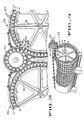
- Each of the above five components 22,24,26,28,30 includes a cylindrical pressure or atmospheric vessel V1,V2,V3,V4,V5 with pairs of closed end walls W (only one being shown in Figure 2) with a stationary T-shaped spiral S (Figs. 3 and 4) secured to the inside surface of the associated vessels V1-V5.
- a reel R is rotatably mounted within each vessel V1-V5, and includes a central shaft CS journaled in each associated pair of closed end walls W.
- a plurality of reel wheels RW are keyed to each shaft CS and have a plurality of container tracks secured thereto with the tracks being illustrated as cooperating pairs of angle bars B. However, the bars may be provided with curved external surfaces to conform to the external shape of the containers C.
- a plurality of rotary pressure valves PV1-4 (Figs. 1 and 2) and associated star wheels SW (only one being shown in Figure 3) serve to transfer the containers between the reels R and their associated pressure valves PV.
- An automatic pressure relief valve PRV is provided on the sterilizer 26 and will open in the event pressure in the sterilizer is excessive. Also, a plurality of bleeder valves BV may be required on sterilizers of the reel and spiral type.
- Containers C to be sterilized are directed into the atmospheric preheater 22 by a feed conveyor FC (Fig. 1) and a rotary atmospheric valve AV-1, and the sterilized containers are discharged from the atmospheric cooler 30 by a rotary valve AV-2 and a discharge conveyor DC.
- the several pressure and atmospheric valves and the reels are driven in the appropriate directions by a conventional variable speed drive which includes a motor M and a plurality of gears (not shown).
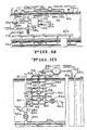
- the sterilizer 26 (Figs 5 and 6) is provided with a large conduit or steam-air log 40 which is connected to a trough 42 by a plurality of branch conduits 44 spaced about 2 - 2 1/2 feet apart for substantially the entire effective length of the sterilizer.
- the trough 42 is sealed to and communicates with the lower portion of the sterilizer.
- the function of the trough 42 is to collect water which condenses out of the steam when the steam contacts the colder containers C and to direct the condensate and other debris through a pressure valve 45 for discharge externally of the sterilizer.
- steam at the desired temperature and pressure is directed into a conventional Y-shaped screen 46 which includes a valve 48 which may be opened to flush contaminates from the screen.
- the steam initially flows through an open valve 50 into the steam-air log 40 and trough 42 for bringing the sterilizer 26 up to sterilizing temperature before the containers C are moved therethrough.
- the valve 50 is then closed and a valve 52 in a branch conduit 54 is opened thereby directing steam through a first steam diaphragm valve 55 which is controlled by a steam temperature controller 56 which senses the temperature at 57.
- a compressed non-condensible gas hereinafter referred to as air
- air is directed through a conduit 62 into the air nozzle 60 and is mixed with the steam and flows through an open valve 64 into the steam-air log 40 thereby completely mixing the air and steam prior to directing the steam-air mixture into the sterilizer 26.
- a shut-off valve 65 may be closed to prevent discharge of air when making repairs or the like.
- a conventional automatic pressure controller 66 detects the pressure in the sterilizer at 67 and adjusts a conventional diaphragm operated valve 68 to control the amount of air directed into the sterilizer through the steam-air log 42.
- the sterilizing system 20 When the sterilizing system 20 is operating at a relatively slow rate of about 250 containers per minute which provides a gradual increase in the temperature differential between the containers C and the heating medium, the system may be operated successfully as thus far described.
- a pure steam system 71 may be mounted on the sterilizer 26 and includes a steam log 72 which is connected to the trough 42 by a plurality of steam conduits 74 spaced at substantially even intervals in the inlet or feed end portion of the sterilizer 26. Adjustable orifices 76 are provided in each conduit 74 and are sized so that the amount of pure steam entering the sterilizer from the steam log 72 may be progressively reduced from the feed end to the opposite end of the steam log.
- Steam is directed from a source of steam (not shown) through a conduit 78, a screen 80 having a normally closed purging valve 81 therein, and into a first branch line 82 having a normally closed valve 84 therein.
- a second branch line 86 has a first normally opened valve 88 and a second normally open valve 90 therein, with the valve portion 94 of a second steam diaphragm valve 96 disposed between valves 88 and 90.
- a second steam temperature controller 98 is connected between the diaphragm valve 96 and a heat sensor 100 by conduits 102 and 104.
- the first and second branch conduits 82,86 communicate with the steam log 72, and it will be appreciated that both valves 88,90 may be closed when repairs are made to the steam diaphragm valve 96 or to the temperature controller 98.
- the steam temperature controller 98 regulates the steam input to the inlet end of the sterilizer which compensates for loss of steam by condensation and is effective to maintain a near constant temperature and steam-air mixture throughout the length of the sterilizer 26.
- the air pressure controller 66 and the air diaphragm valve 68 cooperate to maintain the air pressure and the proportion of air to steam at the desired amounts.
- Pressure gauges 106 are provided at each end of the sterilizer to indicate the pressure within the sterilizer, and the conventional pressure relief valve PRV and bleeder valves BV are provided to prevent excessive pressures from occurring within the sterilizer 26.
- an air log 107 may be connected to the trough 42 by a plurality of spaced conduits 108 and adjustable orifices 109.
- Air from conduit 62 flows through a branch conduit 110 having a valve 111 therein.
- a valve 112 in conduit 62 upstream of the pipe fitting 58 may be partially closed to direct an additional amount of air through the air log 107 thereby adding additional air to the discharge end portion of the sterilizer 26.
- the adjustable orifices 109 in the conduits 108 may be adjusted to progressively increase the air flow into the steam-air mixture in the trough 42 from the feed end to the discharge end thereby providing a larger proportion of air to steam near the discharge end of the sterilizer thus preventing the hot containers from being deformed due to high internal pressure.
- the adjustable orifices 76 in the steam log 72, and the orifices 109 in the air log 107, may be adjusted manually or by a programmed computer. It will also be understood that in all embodiments the rotating reel and containers supported thereon aid in maintaining the steam-air properly mixed.
- the following tests were conducted using a four unit reel and spiral sterilizing system which included an atmospheric preheater having a 3,024 container capacity; a sterilizer having a 2,632 container capacity; a pressure cooler having a 1,176 container capacity; and an atmospheric cooler having a 2,464 container capacity.
- the effective length of the reel and spirals within the several processing units determines the container capacity and accordingly the desired processing time within each unit.
- Each sealed container was filled with a liquid.
- the duration of the test was four hours, and the atmospheric preheater 22 raised the temperature of the contents of the containers to about 210° F. before the containers were transferred into the sterilizer 26.
- the pressure preheater 24 was not used in this test.
- the sterilizer 26 (Fig. 5) was initially heated to operating temperature by steam, and after reaching the operating temperature was heated by only the steam-air mixture from the steam-air log 40.
- the steam temperature controller 56 (Fig. 5) was set at 261° F.
- the air pressure controller 66 was set at about 6 psig. (pounds per square inch gauge) higher than that of saturated steam at 261° F., or about 27 psig.
- the 6 psig. overpressure indicates a theoretical air to steam ratio of about 16.4 percent.
- the indicated temperature at the inlet end of the sterilizer was about 10° less than that at the discharge end of the sterilizer was 261.5° F.
- This temperature gradiant between the inlet and outlet ends of the sterilizer indicates that more steam condenses from the steam-air mixture upon contacting the cooler containers at the feed end of the sterilizer than occurs at the discharge end as previously mentioned.
- the heating medium in the pressure preheater 24 (Figs. 1 and 2) is a steam-air mixture which is substantially the same as that used in the sterilizer 26 (Fig. 5).
- all of the steam and air is directed into the pressure preheater through a steam-air log and trough and is controlled by a steam temperature controller and diaphragm valve; and the air is directed into the steam log and trough and is controlled by a pressure controller and air diaphragm valve in a manner substantially the same as that used in the sterilizer as above described.
- a pure steam log (similar to steam log 72 - Fig.
- the steam-air system for the pressure preheater 24 will not be described in detail. It will be understood that the steam temperature may be held at about 225° - 235° F. and that the air pressure may be controlled at about 2 psig. over that of saturated steam at 235° F.
- the pressure cooler 28 (Fig. 2) receives the containers at about 260° F. from the sterilizer 26 and has cooling water circulating therethrough at between 120° - 180° F. Compressed air is directed into the pressure cooler at about 27 psig. to provide an overriding air pressure therein which is sufficient to prevent the pressure within the containers to permanently damage the hot containers as they are transferred from the sterilizer 26 to the pressure cooler 28 through valve PV3.
- the containers C1 can expand and elongate to the extent not causing permanent damage to the containers nor causing interference with the progress of the containers through the sterilizing system 20.
- the contents of the containers are cooled below the boiling point of water within the pressure cooler 28 and are then transferred by valve PV4 into and through the atmospheric coolers 30 having cooling water therein at between 70° - 120° F.
- the cooled containers are then transferred out of the sterilizing system 20 by the rotary atmospheric valve AV-2 (Fig. 1) and the discharge conveyor DC.
- FIGS 9 and 10 illustrate pertinent portions of a sterilizer 26a of the second embodiment of the invention.
- Components of the sterilizer 26a of the second embodiment which are the same as those described in the first embodiment will be assigned the same numerals as those given to the first embodiment followed by the letter "a".
- the sterilizer 26a of the second embodiment of the invention is the same as that described in the first embodiment and may be operated with or without the aid of the pure steam system 71a as described in the first embodiment. Accordingly, only the differences between the first and second embodiments will be described in detail.
- a pressure controller 66a is of a conventional split range type and detects the pressure within the sterilizer 26a at 67a and transmits that steam-air pressure through a conduit 120 to a double diaphragm valve 122.
- the double diaphragm valve 122 is conventional in the art but as diagrammatically illustrated includes a split housing 124 having an upper chamber 126 communicating with conduit 120 and separated from a lower chamber 128 by a diaphragm 130.
- the lower chamber communicates with the steam-air mixture within the sterilizer 26a at 132.
- a movable rod 133 is connected to the lower surface of the diaphragm 130 and has two valve cores 134 and 136 secured thereto.
- a valve housing 142 includes a first or upper body portion 144 which is split into upper and lower compartments by a central wall 146 which has a port 148 therein which receives valve core 134.
- the upper body portion 144 communicates with the steam-air mixture in the sterilizer 26a at 150 which as illustrated is prevented from moving through port 148.
- the valve housing 142 includes a lower body 154 which is split into an upper compartment 156 and a lower compartment 158 by a wall 160 having a port 162 therein which receives the valve core 136.
- the compartment 156 communicates with the air nozzle 60a disposed in pipe fitting 58a.
- high pressure air from a compressor flows through conduit 62a, open valve 65a, a conduit 164 and into the pipe fitting 58a where steam from the branch conduit 54a combines with the air to direct a steam-air mixture into the steam-air log 40a and into the sterilizer 26a through conduits 44a and the trough 42a as described in regard to the first embodiment.
- valve 136 will open or partially open causing high pressure air to be directed past valve core 136 into the steam-air log until the pressure within the sterilizer 26a reaches the pressure set on the total pressure controller 66a.
- a sterilizer 26b (Fig. 11) of a third embodiment of the invention is similar to that of the first embodiment except that the air is directed into the sterilizer 26b through a tubular shaft 170 to which a reel (not shown), but similar to the reel R (Figs. 3 and 4) is secured. Since the third embodiment is similar to the first embodiment, only the components which differ from those of the first embodiment will be described in detail and equivalent parts will be assigned the same numerals followed by the letter "b".
- the tubular shaft 170 has a plurality of spaced air nozzles 172 and adjustable air orifices 174 secured thereto which may be adjusted to aid in maintaining a consistent steam-air mixture throughout the length of the sterilizer 26b.
- the steam in the steam-air mixture within the sterilizer 26b will condense faster at the feed end of the sterilizer than the discharge end due to greater condensation at the feed end because the temperature difference between the containers and the steam-air is greater at the feed end. If not properly controlled, a greater proportion of air will be present at the feed end as compared to that at the discharge end. Accordingly, the air orifices 174 may be adjusted to direct a gradually decreasing amount of air into the feed end as compared to that entering the discharge end; and steam orifices 176 in the branch conduits 44b leading from the steam log 40b to the trough 42b may be adjusted to progressively increase the amount of steam entering the sterilizer 26b from the discharge end to the feed end of the sterilizer 26b. Alternately, several of the air orifices in the feed end may be completely closed if desired.
- steam is directed from a supply source through the screen 46b and branch conduit 54b and open valve 64b into the steam log 40b. It will be understood that in the third embodiment, only steam is directed into the steam log, and that the steam is directed into the sterilizer 26b through the orifices 176, the conduits 44b and the trough 42b as previously described. Also, the temperature of the steam is controlled by the steam temperature controller 56b which senses the temperature within the sterilizer at 57b and directs appropriate signals to the steam diaphragm valve 55b.
- High pressure air is directed from a source of compressed air into a conduit 62b through an air diaphragm valve 68b and into a swivel joint 178 which directs the air into the tubular shaft 170 for injection into the sterilizer 26b through orifices 174 and nozzles 172.
- a pressure controller 66b senses the pressure at 67b and sends appropriate signals to the air diaphragm valve 68b which controls the volume of air entering the shaft 170 and the sterilizer 26b.
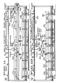
- a sterilizer 26c (Fig. 12) of the fourth embodiment is similar to the first embodiment except that a separate steam log 40c is provided for steam only, and an air log 180 is provided for air only.
- the steam log 40c is connected to the trough 42c by a plurality of conduits 44c having orifices 182 therein.
- the air log 180 extends approximately the full length of the sterilizer and is connected to the trough by a plurality of conduits 184 and orifices 186.
- the orifices may be adjusted to minimize or close the orifices at the feed end of the air log. This adjustment can be done manually or by computer control.
- Steam is directed from a supply source into the screen 46c, a conduit 54c, a core 188 of a steam diaphragm valve 55c and a valved conduit 190 to the steam log 40c.
- the steam temperature within the sterilizer is sensed at 57c by a steam temperature controller 56c which sends appropriate signals to the diaphragm valve 55c which maintains the desired temperature within the sterilizer 26c.
- High pressure air is directed into the air log 180 through a valved conduit 62c, the core 194 of the air diaphragm valve 70c and a valve conduit 196.
- a pressure controller 66c senses the pressure within the sterilizer 26c at 67c and transmits appropriate signals to the air diaphragm valve 70c thereby maintaining the desired pressure within the sterilizer 26c.
- a sterilizer 26d (Figs. 13 and 14) of the fifth embodiment of the invention is similar to the first embodiment except that a separate steam log 40d is provided for steam alone, and an air log 200 is provided for transferring air directly into the upper portion of the sterilizer 26d.
- the steam log 40d is connected to the trough 42d by a plurality of conduits 44d having orifices 202 therein.
- the air log 200 extends approximately the full length of the sterilizer and is connected directly to the upper portion of the sterilizer 26d by a plurality of conduits 203 and orifices 204.
- Steam is directed from a supply source into a screen 46d, a conduit 54d, the core 206 of a steam diaphragm valve 55d, and a valve conduit 208 to the steam log 40d.
- the steam temperature within the sterilizer is sensed at 57d by a steam temperature controller 56d which sends appropriate signals to the diaphragm valve 55d which maintains the desired temperature within the sterilizer 26d.
- High pressure air is directed into the air log 200 through a valve conduit 62d, the core 206 of the air diaphragm valve 70d and a valved conduit 210.
- a pressure controller 66d senses the pressure within the sterilizer 26d at 67d and transmits appropriate signals to the air diaphragm valve 70d thereby maintaining the desired pressure within the sterilizer 26d.
- the orifices 204 can be manually or computer adjusted to close or adjust the amount of air discharged into the feed end as in the fourth embodiment of the invention.
- the air log 200 is illustrated as being on the upper portion of the front of the sterilizer 26d, it will be appreciated that, if desired, the air log 200 may be positioned on the top of the sterilizer at 200′ (Fig. 14) or at the rear of the sterilizer at 200 ⁇ .
Landscapes
- Life Sciences & Earth Sciences (AREA)
- Engineering & Computer Science (AREA)
- Wood Science & Technology (AREA)
- Zoology (AREA)
- Chemical & Material Sciences (AREA)
- Food Science & Technology (AREA)
- Polymers & Plastics (AREA)
- Apparatus For Disinfection Or Sterilisation (AREA)
Applications Claiming Priority (2)
| Application Number | Priority Date | Filing Date | Title |
|---|---|---|---|
| US7549387A | 1987-07-20 | 1987-07-20 | |
| US75493 | 1987-07-20 |
Publications (2)
| Publication Number | Publication Date |
|---|---|
| EP0302306A2 true EP0302306A2 (de) | 1989-02-08 |
| EP0302306A3 EP0302306A3 (de) | 1989-10-18 |
Family
ID=22126128
Family Applications (1)
| Application Number | Title | Priority Date | Filing Date |
|---|---|---|---|
| EP88111687A Withdrawn EP0302306A3 (de) | 1987-07-20 | 1988-07-20 | Dampf-Luftrotations-Sterilisierungssystem und Verfahren |
Country Status (1)
| Country | Link |
|---|---|
| EP (1) | EP0302306A3 (de) |
Cited By (7)
| Publication number | Priority date | Publication date | Assignee | Title |
|---|---|---|---|---|
| EP0457181A1 (de) * | 1990-05-09 | 1991-11-21 | Fmc Corporation | Drehende Sterilisiervorrichtung für Behälter aus Kunststoff |
| NL9300070A (nl) * | 1992-02-14 | 1993-09-01 | Fmc Corp | Roterende conserveerinrichting met een enkel vat. |
| WO2000027227A1 (en) * | 1998-11-06 | 2000-05-18 | Fmc Corporation | Controller and method for administering and providing on-line handling of deviations in a rotary sterilization process |
| US6410066B1 (en) | 1998-11-06 | 2002-06-25 | Fmc Technologies, Inc. | Controller and method for administering and providing on-line handling of deviations in a continuous oven cooking process |
| US6440361B2 (en) | 1998-11-06 | 2002-08-27 | Fmc Technologies, Inc. | Controller and method for administering and providing on-line handling of deviations in a hydrostatic sterilization process |
| US6472008B2 (en) | 1998-11-06 | 2002-10-29 | Fmc Technologies, Inc. | Method for administering and providing on-line correction of a batch sterilization process |
| US6518550B1 (en) | 1999-03-01 | 2003-02-11 | Fmc Corporation | System, controller, computer readable memory, and method for precise on-line control of heat transfer in a food preparation process |
Family Cites Families (5)
| Publication number | Priority date | Publication date | Assignee | Title |
|---|---|---|---|---|
| US1491092A (en) * | 1922-02-04 | 1924-04-22 | Nelson H Fooks | Heat-treating substance packed in sealed receptacles |
| US2536115A (en) * | 1945-09-04 | 1951-01-02 | Fmc Corp | Method of and apparatus for heattreating evaporated milk |
| US3365311A (en) * | 1966-07-22 | 1968-01-23 | Schmidt John | Method of processing packaged food products |
| US3511168A (en) * | 1968-04-22 | 1970-05-12 | Fmc Corp | Apparatus for processing products in sealed containers |
| DE2559264A1 (de) * | 1975-12-31 | 1977-07-14 | Oskar Ing Grad Neiss | Durchlaufverfahren zur hitzesterilisierung und vorrichtung zur durchfuehrung dieses verfahrens |
-
1988
- 1988-07-20 EP EP88111687A patent/EP0302306A3/de not_active Withdrawn
Cited By (8)
| Publication number | Priority date | Publication date | Assignee | Title |
|---|---|---|---|---|
| EP0457181A1 (de) * | 1990-05-09 | 1991-11-21 | Fmc Corporation | Drehende Sterilisiervorrichtung für Behälter aus Kunststoff |
| NL9300070A (nl) * | 1992-02-14 | 1993-09-01 | Fmc Corp | Roterende conserveerinrichting met een enkel vat. |
| WO2000027227A1 (en) * | 1998-11-06 | 2000-05-18 | Fmc Corporation | Controller and method for administering and providing on-line handling of deviations in a rotary sterilization process |
| US6410066B1 (en) | 1998-11-06 | 2002-06-25 | Fmc Technologies, Inc. | Controller and method for administering and providing on-line handling of deviations in a continuous oven cooking process |
| US6416711B2 (en) | 1998-11-06 | 2002-07-09 | Fmc Technologies, Inc. | Controller and method for administering and providing on-line handling of deviations in a rotary sterilization process |
| US6440361B2 (en) | 1998-11-06 | 2002-08-27 | Fmc Technologies, Inc. | Controller and method for administering and providing on-line handling of deviations in a hydrostatic sterilization process |
| US6472008B2 (en) | 1998-11-06 | 2002-10-29 | Fmc Technologies, Inc. | Method for administering and providing on-line correction of a batch sterilization process |
| US6518550B1 (en) | 1999-03-01 | 2003-02-11 | Fmc Corporation | System, controller, computer readable memory, and method for precise on-line control of heat transfer in a food preparation process |
Also Published As
| Publication number | Publication date |
|---|---|
| EP0302306A3 (de) | 1989-10-18 |
Similar Documents
| Publication | Publication Date | Title |
|---|---|---|
| EP0213644B1 (de) | Verfahren zum Versichern der Stabilität eines Flüssigkeitsstandes in einem Druckraum | |
| EP0302306A2 (de) | Dampf-Luftrotations-Sterilisierungssystem und Verfahren | |
| US5374435A (en) | Method of batch cooking and packing fruit and vegetable pieces | |
| US4591463A (en) | Method and apparatus for treating liquid materials | |
| CN112868976A (zh) | 连续低温食物巴氏灭菌系统和方法 | |
| DK171696B1 (da) | Pasteuriseringsapparat | |
| US5362509A (en) | Method and apparatus for making a frozen mass of drinkable product ready for treatment | |
| US4539903A (en) | Filling apparatus | |
| US20060029488A1 (en) | Method for controlling flow of process materials | |
| EP0692198B1 (de) | Verfahren und Vorrichtung zum Erwärmen und Sterilisieren von Lebensmitteln | |
| EP0247310B1 (de) | Behandlungs- und Verpackungssystem für flexible Behälter | |
| EP0437499B1 (de) | Verfahren und vorrichtung für die pasteurisierung einer kontinuierlichen erzeugniskette | |
| JPH11503327A (ja) | 流動材料を処理する装置および方法 | |
| US5472042A (en) | Apparatus for managing retort over-pressure during pressure cooling | |
| US5344609A (en) | Method and apparatus for sterilization with incremental pressure reduction | |
| CA1236437A (en) | Systems for feeding liquid substances | |
| GB2137865A (en) | Sterilization apparatus | |
| EP0692196B1 (de) | Sterilisiervorrichtung | |
| EP0692197B1 (de) | Vorrichtung und Verfahren zum Sterilisieren von Lebensmitteln | |
| US5215002A (en) | Single vessel rotary processor | |
| US3365311A (en) | Method of processing packaged food products | |
| US5746808A (en) | Thermal processing and packaging system employing an intermediate degassing tank | |
| Anderson et al. | Continuous steam sterilization segmented-flow aseptic processing of particle foods | |
| US1491092A (en) | Heat-treating substance packed in sealed receptacles | |
| SU1153879A1 (ru) | Устройство дл термической обработки пищевых продуктов |
Legal Events
| Date | Code | Title | Description |
|---|---|---|---|
| PUAI | Public reference made under article 153(3) epc to a published international application that has entered the european phase |
Free format text: ORIGINAL CODE: 0009012 |
|
| AK | Designated contracting states |
Kind code of ref document: A2 Designated state(s): AT BE DE FR GB IT NL |
|
| PUAL | Search report despatched |
Free format text: ORIGINAL CODE: 0009013 |
|
| AK | Designated contracting states |
Kind code of ref document: A3 Designated state(s): AT BE DE FR GB IT NL |
|
| 17P | Request for examination filed |
Effective date: 19900122 |
|
| 17Q | First examination report despatched |
Effective date: 19910307 |
|
| STAA | Information on the status of an ep patent application or granted ep patent |
Free format text: STATUS: THE APPLICATION HAS BEEN WITHDRAWN |
|
| 18W | Application withdrawn |
Withdrawal date: 19910618 |
|
| R18W | Application withdrawn (corrected) |
Effective date: 19910618 |