EP0302385B1 - Dispositif et procédé de calibrage d'un capteur de distribution de force - Google Patents
Dispositif et procédé de calibrage d'un capteur de distribution de force Download PDFInfo
- Publication number
- EP0302385B1 EP0302385B1 EP88112171A EP88112171A EP0302385B1 EP 0302385 B1 EP0302385 B1 EP 0302385B1 EP 88112171 A EP88112171 A EP 88112171A EP 88112171 A EP88112171 A EP 88112171A EP 0302385 B1 EP0302385 B1 EP 0302385B1
- Authority
- EP
- European Patent Office
- Prior art keywords
- pressure
- sensors
- analysis device
- sensor
- sensor arrangement
- Prior art date
- Legal status (The legal status is an assumption and is not a legal conclusion. Google has not performed a legal analysis and makes no representation as to the accuracy of the status listed.)
- Expired - Lifetime
Links
- 238000000034 method Methods 0.000 title claims description 15
- 238000009826 distribution Methods 0.000 title claims description 6
- 238000005259 measurement Methods 0.000 claims description 11
- 239000012528 membrane Substances 0.000 claims description 11
- 239000012530 fluid Substances 0.000 claims description 7
- 239000007788 liquid Substances 0.000 claims description 2
- 230000014759 maintenance of location Effects 0.000 claims 3
- 238000011156 evaluation Methods 0.000 description 13
- 230000008878 coupling Effects 0.000 description 3
- 238000010168 coupling process Methods 0.000 description 3
- 238000005859 coupling reaction Methods 0.000 description 3
- 230000001681 protective effect Effects 0.000 description 3
- 238000011088 calibration curve Methods 0.000 description 1
- 230000002093 peripheral effect Effects 0.000 description 1
- 238000007789 sealing Methods 0.000 description 1
- 125000006850 spacer group Chemical group 0.000 description 1
- 230000007704 transition Effects 0.000 description 1
Images

Classifications
-
- G—PHYSICS
- G01—MEASURING; TESTING
- G01L—MEASURING FORCE, STRESS, TORQUE, WORK, MECHANICAL POWER, MECHANICAL EFFICIENCY, OR FLUID PRESSURE
- G01L25/00—Testing or calibrating of apparatus for measuring force, torque, work, mechanical power, or mechanical efficiency
Definitions
- the invention relates to a method according to the preamble of claim 1 and a device according to the preamble of claim 6.
- each individual sensor has so far been loaded with a constant load (weight) and the proportionality factor and, if appropriate, the position of the zero point of the sensor have been determined from the difference between the output signals with and without load. This procedure is time-consuming, cumbersome and leads to incorrect calibrations despite careful implementation.
- This object is achieved by measuring and recording the output signals or output amplitudes of all sensors in the unloaded state, at least partially bringing the entire sensor arrangement into a fluid medium (air, liquid), the pressure of which is above atmospheric pressure and the output signals of the sensors as well measures and records the pressure of the fluid medium, determines the proportionality factors and zero points of all sensors from the measurement data and stores them in the evaluation device, and in all subsequent measurements multiplies the sensor output signals after being shifted by the measured zero point values by the relevant stored proportionality factor. If you carry out the method in this way, you will surprisingly get much more precise calibration results than was previously the case. This appears to be due in particular to the fact that the mechanical (inevitable) coupling between the sensors falsifies the measurement result in the discrete calibration of all individual sensors.
- the individual sensors are loaded unevenly in current measurements, they are also juxtaposed lying sensors are exposed to similar values due to the normally occurring "soft" transitions in force or pressure distribution.
- the mechanical coupling between the individual sensors has less of an influence in the current measurement than in the discrete calibration, so that the method according to the invention loads the sensor arrangement in a manner which is much more similar to the current measurement.
- the sensor arrangement is sealed off from the fluid medium with a protective cover.
- the protective cover falsifies the force applied by the fluid medium to the sensor arrangement practically not guarantees, however, that the supply cable to the sensor arrangement can be connected to the downstream evaluation device without sealing means.
- the method becomes particularly simple when the protective cover with the fluid medium lying thereon is provided on one side of the sensor arrangement and the sensor arrangement is supported over the entire surface on the other side.
- Suitable for carrying out the method is a device which has a pressure chamber which can be sealed off from the atmosphere and is provided with a filling opening and a pressure sensor.
- the filling opening is connected to a pump, which may also be installed permanently on the pressure chamber.
- the pressure space is closed on one side by a membrane and can be fixed relative to a base area.
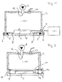
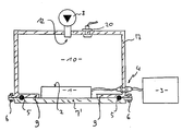
- a pressure chamber 10 is formed by a hood 7 which sits on a bottom surface 7 'and is sealed off from it by means of seals 5.
- a pressure sensor 20 which is connected to a display arrangement, not shown here. Furthermore, an inlet connector 12 is mounted in the hood 7, which is connected to a pump 8. Finally, a gas-tight plug connection 4 is provided in the hood 7, via which one can connect a sensor arrangement 1 introduced into the pressure chamber 10 to the associated evaluation device 3.
- Calibration is preferably carried out in such a way that the output signals of the sensor 20 are fed directly to the downstream evaluation device 3 and the calibration curves are stored in the evaluation device 3 as digital values which are used in subsequent current measurements to be offset against the measured values for their calibration.
- the arrangement according to FIG. 2 differs from that according to FIG. 1 in that the hood 7 is connected to the floor 7 'via an articulated connection 15 and can be held immovably to the floor 7' via a latching hook 14.
- the hood 7 has an inwardly projecting peripheral flange 9 to which a membrane 11 is tightly attached. If one wants to calibrate a sensor arrangement 1 with the aid of this device, one places the sensor arrangement 1 on the counter surface 13 formed by the base 7 'and pumps up the pressure chamber 10 via the pump 8. The membrane 1 then applies a uniform pressure to the sensor arrangement 1 without the entire sensor arrangement 1 having to be brought into the pressure space.
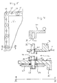
- the articulated connection 15 and the latching hook 14 are replaced by holding means 21 which comprise threaded bolts 22 which are fastened to the base 7 ′ and by bores in outwardly projecting flange edges the hood 7 (with play) protrude.
- holding means 21 comprise threaded bolts 22 which are fastened to the base 7 ′ and by bores in outwardly projecting flange edges the hood 7 (with play) protrude.
- nuts 23 and 24 are screwed onto the bolts 21 on both sides of the flange of the hood 7. This arrangement ensures that the hood 7 and thus also the membrane 11 attached to it can be held exactly above the counter surface 13 so that the membrane 11 runs essentially smoothly when the sensor arrangement 1 is inserted.
- the surface part of the membrane 11 that is not above the sensor arrangement is preferred 1 lies, filled with spacer elements 37 ', which have a thickness corresponding to the sensor arrangement 1. If the pressure chamber 10 is now pressurized, bulges of the membrane 11 can only occur in the remaining gaps, so that the membrane 11 can be made relatively thin and thus elastic.
- the device designed in this way can be set to different-sized sensor arrangements 1. If you want to calibrate a sensor arrangement 1 up to peak measured values of 250 N / cm2, a total force which is 930,000 N already occurs with an area of the membrane 11 of 30 cm ⁇ 40 cm. For this reason, it is advantageous to provide a large number of such holding devices 21.
- the holding device 21 comprises a plurality of threaded bolts 21 which are fastened to the edge of the base 7 'so as to be rotatable but fixed in the longitudinal direction.
- This attachment takes place on the one hand by means of axial spherical roller bearings 27 and on the other hand by means of snap rings 28 which rest on the base 13 of the base 7 'via washers 29.
- the axial bearings 27 are arranged on the tension side, so that the high forces during calibration (when the pressure chamber is under pressure) are absorbed by these bearings.
- the threaded bolts 22 are seated in corresponding internal threads 31 in the outwardly projecting flange of the hood 7, the hood 7 being supported with respect to the base 7 ′ by springs 30. These springs 30 ensure that the frictional forces occurring when the bolts 22 are rotated are determined almost exclusively by the friction in the internal thread 31.
- the plurality of threaded bolts 25 each have clamped chain wheels 25 at their lower end (in FIG. 4), which are fixed on the threaded bolts 22 by nuts 26. About this chain wheels 25 runs a (single) chain 35 all around the edge of the bottom 7 ', which is held in engagement with the chain wheels 25 via deflection or tensioning chain wheels 36 becomes. If you now turn one of the threaded bolts 22, for example via a hand crank 34, which has a push-on opening 33 with a molded-on projection 32 corresponding to a step 32 'in the threaded bolt 22, this rotation is transmitted to all threaded bolts 22, so that the lifting and lowering of the bolts evenly Hood 7 relative to the floor 7 'is made possible.
- the holding means 21 comprise hydraulic cylinders which are fed by a common pressure source. This connection to a common pressure source ensures simultaneous actuation of the hydraulic cylinders, that is to say coupling all the pressure cylinders to one another.
- the evaluation device 3 is equipped with appropriate means (microprocessor) and with a valve between the pressure source 8 and the opening 12 in a controlling connection. Furthermore, the microprocessor of the evaluation device 3 is designed such that the valve is controlled so that the pressure generated in the pressure chamber 10 is adjusted in accordance with a calibration program.
- the pump 8 first generate a maximum pressure in the pressure chamber 10, then close the opening 12 (for example via a non-return valve) and via a valve (not shown) controlled by the evaluation device 3 the pressure in accordance with the desired Release calibration values into the atmosphere.
- calibration takes place both with increasing and also with falling pressure values, so that a (possibly present) hysteresis behavior of the sensors can be stored and taken into account in later measurements.
- the evaluation device 3 queries all sensors, accepts the instantaneous measured values as calibration values and stores them in the form of points in a characteristic field. Then the pressure is brought to the next calibration value.
Landscapes
- Physics & Mathematics (AREA)
- General Physics & Mathematics (AREA)
- Measuring Fluid Pressure (AREA)
Claims (10)
- Procédé de calibrage d'un appareil capteur de mesure avec un dispositif d'exploitation monté en aval pour la mesure de la distribution de forces ou pressions sur une surface pourvue de capteurs, par exemple de capteurs séparés, caractérisé par le fait que les signaux ou amplitudes de sortie de tous les capteurs sont mesurés et enregistrés à l'état non chargé, l'appareil capteur de mesure entier est placé au moins en partie dans un fluide, par exemple air, liquide, dont la pression est supérieure à la pression atmosphérique, et les signaux de sortie des capteurs et la pression du fluide sont mesurés et enregistrés, les facteurs de proportionnalité et les zéros de tous les capteurs sont déterminés à partir de données de mesure et mis en mémoire dans le dispositif d'exploitation, et lors de toutes les mesures suivantes, les signaux de sortie des capteurs sont, après décalage des valeurs à zéro mesurées, multipliés par les facteurs de proportionnalité mis en mémoire correspondants.
- Procédé de calibrage selon la revendication 1, caractérisé par le fait que la pression supérieure à la pression atmosphérique est commandée par le dispositif d'exploitation.
- Procédé de calibrage selon la revendication 2, caractérisé par le fait que la pression supérieure à la pression atmosphérique est contrôlée par le dispositif d'exploitation par l'intermédiaire d'un capteur de valeur mesurée.
- Dispositif pour la mise en oeuvre d'un procédé de calibrage d'un appareil capteur de mesure avec un dispositif d'exploitation monté en aval de cet appareil capteur pour la mesure de la distribution de forces ou pressions sur une surface pourvue de capteurs, par exemple de capteurs séparés, caractérisé par le fait qu'il est prévu un espace à pression (10) qui peut être isolé de l'atmosphère, est pourvu d'un orifice de remplissage (12) et d'un capteur de mesure de pression (20) et est construit de façon telle que l'appareil capteur de mesure (1) peut être soumis à la pression dans cet espace à pression (10), et que le dispositif d'exploitation présente des mémoires pour mémoriser des facteurs de proportionnalité et des zéros de tous les capteurs et les prendre en considération lors des mesures suivantes.
- Dispositif selon la revendication 4, caractérisé par le fait que l'espace à pression (10) est fermé sur un côté par une membrane (11) et peut être fixé vis-à-vis d'une face de base (13) d'un fond (7').
- Dispositif selon la revendication 5, caractérisé par le fait que l'espace à pression (10) est formé dans une hotte (7) qui est fermée sur un côté par la membrane (11) et peut être fixée par ce côté vis-à-vis du fond (7'), à une distance donnée, par des moyens de fixation réglables.
- Dispositif selon la revendication 6, caractérisé par le fait qu'un grand nombre de moyens de fixation (21) sont prévus entre la hotte (7) et le fond (7') pour la répartition des forces qui apparaissent et sont couplés entre eux par des moyens de liaison (25, 35) pour leur réglage simultané.
- Dispositif selon l'une des revendications 4 à 7, caractérisé par le fait que les mémoires du dispositif d'exploitation (3) sont construites de façon telle que des courbes caractéristiques de tous les capteurs puissent être mises en mémoire et être appelées pour la linéarisation des signaux de sortie actuels des capteurs.
- Dispositif selon l'une des revendications 4 à 8, caractérisé par le fait que le dispositif d'exploitation (3) est construit et relié au capteur de mesure de pression (20) de façon telle qu'il associe automatiquement les valeurs de sortie de l'appareil capteur de mesure aux valeurs de pression mesurées.
- Dispositif selon l'une des revendications 4 à 9, caractérisé par le fait que le dispositif d'exploitation (3) est en liaison de commande avec une vanne réglable à distance placée entre l'orifice de remplissage (12) et une source de pression, et qu'il est construit de façon telle que la pression dans l'espace à pression (10) peut être réglée automatiquement par l'intermédiaire de la vanne.
Applications Claiming Priority (2)
| Application Number | Priority Date | Filing Date | Title |
|---|---|---|---|
| DE3725471 | 1987-07-31 | ||
| DE3725471 | 1987-07-31 |
Publications (3)
| Publication Number | Publication Date |
|---|---|
| EP0302385A2 EP0302385A2 (fr) | 1989-02-08 |
| EP0302385A3 EP0302385A3 (en) | 1990-12-05 |
| EP0302385B1 true EP0302385B1 (fr) | 1993-03-17 |
Family
ID=6332830
Family Applications (1)
| Application Number | Title | Priority Date | Filing Date |
|---|---|---|---|
| EP88112171A Expired - Lifetime EP0302385B1 (fr) | 1987-07-31 | 1988-07-27 | Dispositif et procédé de calibrage d'un capteur de distribution de force |
Country Status (2)
| Country | Link |
|---|---|
| EP (1) | EP0302385B1 (fr) |
| DE (1) | DE3879312D1 (fr) |
Cited By (1)
| Publication number | Priority date | Publication date | Assignee | Title |
|---|---|---|---|---|
| US6993954B1 (en) | 2004-07-27 | 2006-02-07 | Tekscan, Incorporated | Sensor equilibration and calibration system and method |
Families Citing this family (9)
| Publication number | Priority date | Publication date | Assignee | Title |
|---|---|---|---|---|
| US4860587A (en) * | 1988-05-31 | 1989-08-29 | Keller Carl E | Stress gauge |
| FR2656096B1 (fr) * | 1989-12-15 | 1992-04-17 | Clecim Sa | Dispositif d'etalonnage de capteur. |
| US5440237A (en) * | 1993-06-01 | 1995-08-08 | Incontrol Solutions, Inc. | Electronic force sensing with sensor normalization |
| FR2725519B1 (fr) * | 1994-10-10 | 1996-12-13 | Ainf Sa | Procede et dispositif de test de l'integrite d'un capteur de deformation |
| DE10119600A1 (de) * | 2001-04-21 | 2002-10-31 | Bosch Gmbh Robert | Einrichtung und Verfahren zur Kalibrierung eines Sensors |
| EP3657147A1 (fr) | 2018-11-21 | 2020-05-27 | Bayer AG | Dispositif de calibrage pour calibrer un dispositif de mesure de pression et utilisation correspondante pour ce dispositif de calibrage |
| CN113310624A (zh) * | 2021-06-24 | 2021-08-27 | 吉林大学 | 一种驻车制动力传感器校准装置 |
| CN113654720B (zh) * | 2021-09-02 | 2023-11-17 | 安徽中科本元信息科技有限公司 | 一种气压式柔性力敏传感器标定装置及标定方法 |
| CN115389099A (zh) * | 2022-10-26 | 2022-11-25 | 北京中科富海低温科技有限公司 | 压力传感器标定装置 |
Family Cites Families (2)
| Publication number | Priority date | Publication date | Assignee | Title |
|---|---|---|---|---|
| DE1473497A1 (de) * | 1964-10-21 | 1969-05-08 | Kistler Instrumente Ag | Druckmessgeraet |
| FR2608760B1 (fr) * | 1986-05-14 | 1989-03-10 | Lorraine Laminage | Procede et dispositif d'actionnement controle des capteurs de contraintes pour leur etalonnage |
-
1988
- 1988-07-27 EP EP88112171A patent/EP0302385B1/fr not_active Expired - Lifetime
- 1988-07-27 DE DE8888112171T patent/DE3879312D1/de not_active Expired - Fee Related
Cited By (1)
| Publication number | Priority date | Publication date | Assignee | Title |
|---|---|---|---|---|
| US6993954B1 (en) | 2004-07-27 | 2006-02-07 | Tekscan, Incorporated | Sensor equilibration and calibration system and method |
Also Published As
| Publication number | Publication date |
|---|---|
| EP0302385A2 (fr) | 1989-02-08 |
| EP0302385A3 (en) | 1990-12-05 |
| DE3879312D1 (de) | 1993-04-22 |
Similar Documents
| Publication | Publication Date | Title |
|---|---|---|
| DE3447008C2 (de) | Dichtungsvorrichtung für einen Absperrschieber | |
| DE3620391C2 (fr) | ||
| DE2839180C2 (fr) | ||
| EP0302385B1 (fr) | Dispositif et procédé de calibrage d'un capteur de distribution de force | |
| DE3111434C2 (de) | Vorrichtung zum Messen der Axialkraft in einer mittels Rollenlagern gelagerten Welle | |
| DE2855582A1 (de) | Druckschalter | |
| DE2443158C2 (de) | Verfahren und Vorrichtung zum Bestimmen der Schubspannung in pulverigem und/oder körnigem Material | |
| DE19755244C1 (de) | Verschlußsystem für Chromatographiesäulen | |
| DE3238951A1 (de) | Kraftaufnehmer | |
| DE3341721C2 (de) | Prüfvorrichtung für Fahrzeugräder | |
| CH623225A5 (fr) | ||
| EP0179278A2 (fr) | Capteur de pression | |
| DE2749538C3 (de) | Anordnung zum Messen der Vorspannung eines insbesondere zum Verschluß eines Reaktordruckbehälters dienenden Gewindebolzens | |
| DE102010018417A1 (de) | Verfahren und Vorrichtung zum Herstellen von stapelförmigen Bauteilen | |
| DE1773367A1 (de) | Vorrichtung zur UEberpruefung von Kraftfahrzeugreifen | |
| DE3744084C2 (fr) | ||
| EP3276310B1 (fr) | Dispositif de mesure de longueur | |
| DE102017130769A1 (de) | Messrolle | |
| EP1212564B1 (fr) | Dispositif pour controler une soupape de securite | |
| DE4015321A1 (de) | Verfahren zum ueberpruefen des korrekten sitzes einer dichtflaeche | |
| EP4425143A1 (fr) | Dispositif et procédé de mesure de la force de pression des talons d'un pneu | |
| EP0069280A1 (fr) | Dispositif indicateur pour freins de véhicules, notamment freins à disques de véhicules ferroviaires | |
| DE3204817A1 (de) | Druckdichte durchfuehrung fuer mess-, regel- und steuergeraete o.dgl. | |
| DE1478850C3 (de) | Manipuliervorrichtung | |
| DE4329221A1 (de) | Vorrichtung zum Einstellen von Spaltweiten im Strahlengang von Spektrometern |
Legal Events
| Date | Code | Title | Description |
|---|---|---|---|
| PUAI | Public reference made under article 153(3) epc to a published international application that has entered the european phase |
Free format text: ORIGINAL CODE: 0009012 |
|
| AK | Designated contracting states |
Kind code of ref document: A2 Designated state(s): BE CH DE FR GB IT LI |
|
| PUAL | Search report despatched |
Free format text: ORIGINAL CODE: 0009013 |
|
| AK | Designated contracting states |
Kind code of ref document: A3 Designated state(s): BE CH DE FR GB IT LI |
|
| 17P | Request for examination filed |
Effective date: 19901217 |
|
| 17Q | First examination report despatched |
Effective date: 19910730 |
|
| GRAA | (expected) grant |
Free format text: ORIGINAL CODE: 0009210 |
|
| AK | Designated contracting states |
Kind code of ref document: B1 Designated state(s): BE CH DE FR GB IT LI |
|
| PG25 | Lapsed in a contracting state [announced via postgrant information from national office to epo] |
Ref country code: IT Free format text: LAPSE BECAUSE OF FAILURE TO SUBMIT A TRANSLATION OF THE DESCRIPTION OR TO PAY THE FEE WITHIN THE PRE;WARNING: LAPSES OF ITALIAN PATENTS WITH EFFECTIVE DATE BEFORE 2007 MAY HAVE OCCURRED AT ANY TIME BEFORE 2007. THE CORRECT EFFECTIVE DATE MAY BE DIFFERENT FROM THE ONE RECORDED.SCRIBED TIME-LIMIT Effective date: 19930317 Ref country code: BE Effective date: 19930317 |
|
| ET | Fr: translation filed | ||
| REF | Corresponds to: |
Ref document number: 3879312 Country of ref document: DE Date of ref document: 19930422 |
|
| GBT | Gb: translation of ep patent filed (gb section 77(6)(a)/1977) |
Effective date: 19930406 |
|
| PG25 | Lapsed in a contracting state [announced via postgrant information from national office to epo] |
Ref country code: LI Effective date: 19930731 Ref country code: CH Effective date: 19930731 |
|
| PLBE | No opposition filed within time limit |
Free format text: ORIGINAL CODE: 0009261 |
|
| STAA | Information on the status of an ep patent application or granted ep patent |
Free format text: STATUS: NO OPPOSITION FILED WITHIN TIME LIMIT |
|
| 26N | No opposition filed | ||
| REG | Reference to a national code |
Ref country code: CH Ref legal event code: PL |
|
| REG | Reference to a national code |
Ref country code: CH Ref legal event code: AUV Free format text: DAS OBENGENANNTE PATENT IST, MANGELS BEZAHLUNG DER 6. JAHRESGEBUEHR GELOESCHT WORDEN. |
|
| REG | Reference to a national code |
Ref country code: GB Ref legal event code: IF02 |
|
| PGFP | Annual fee paid to national office [announced via postgrant information from national office to epo] |
Ref country code: GB Payment date: 20040713 Year of fee payment: 17 |
|
| PGFP | Annual fee paid to national office [announced via postgrant information from national office to epo] |
Ref country code: FR Payment date: 20040720 Year of fee payment: 17 |
|
| PGFP | Annual fee paid to national office [announced via postgrant information from national office to epo] |
Ref country code: DE Payment date: 20040927 Year of fee payment: 17 |
|
| PG25 | Lapsed in a contracting state [announced via postgrant information from national office to epo] |
Ref country code: GB Free format text: LAPSE BECAUSE OF NON-PAYMENT OF DUE FEES Effective date: 20050727 |
|
| PG25 | Lapsed in a contracting state [announced via postgrant information from national office to epo] |
Ref country code: DE Free format text: LAPSE BECAUSE OF NON-PAYMENT OF DUE FEES Effective date: 20060201 |
|
| GBPC | Gb: european patent ceased through non-payment of renewal fee |
Effective date: 20050727 |
|
| PG25 | Lapsed in a contracting state [announced via postgrant information from national office to epo] |
Ref country code: FR Free format text: LAPSE BECAUSE OF NON-PAYMENT OF DUE FEES Effective date: 20060331 |
|
| REG | Reference to a national code |
Ref country code: FR Ref legal event code: ST Effective date: 20060331 |