EP0302409A2 - Unité d'engrenage et d'embrayage pour véhicule à moteur à deux roues - Google Patents
Unité d'engrenage et d'embrayage pour véhicule à moteur à deux roues Download PDFInfo
- Publication number
- EP0302409A2 EP0302409A2 EP88112343A EP88112343A EP0302409A2 EP 0302409 A2 EP0302409 A2 EP 0302409A2 EP 88112343 A EP88112343 A EP 88112343A EP 88112343 A EP88112343 A EP 88112343A EP 0302409 A2 EP0302409 A2 EP 0302409A2
- Authority
- EP
- European Patent Office
- Prior art keywords
- clutch
- gear
- coupling member
- output shaft
- shaft
- Prior art date
- Legal status (The legal status is an assumption and is not a legal conclusion. Google has not performed a legal analysis and makes no representation as to the accuracy of the status listed.)
- Ceased
Links
Images


Classifications
-
- F—MECHANICAL ENGINEERING; LIGHTING; HEATING; WEAPONS; BLASTING
- F02—COMBUSTION ENGINES; HOT-GAS OR COMBUSTION-PRODUCT ENGINE PLANTS
- F02B—INTERNAL-COMBUSTION PISTON ENGINES; COMBUSTION ENGINES IN GENERAL
- F02B61/00—Adaptations of engines for driving vehicles or for driving propellers; Combinations of engines with gearing
- F02B61/02—Adaptations of engines for driving vehicles or for driving propellers; Combinations of engines with gearing for driving cycles
-
- B—PERFORMING OPERATIONS; TRANSPORTING
- B62—LAND VEHICLES FOR TRAVELLING OTHERWISE THAN ON RAILS
- B62M—RIDER PROPULSION OF WHEELED VEHICLES OR SLEDGES; POWERED PROPULSION OF SLEDGES OR SINGLE-TRACK CYCLES; TRANSMISSIONS SPECIALLY ADAPTED FOR SUCH VEHICLES
- B62M11/00—Transmissions characterised by the use of interengaging toothed wheels or frictionally-engaging wheels
- B62M11/04—Transmissions characterised by the use of interengaging toothed wheels or frictionally-engaging wheels of changeable ratio
- B62M11/06—Transmissions characterised by the use of interengaging toothed wheels or frictionally-engaging wheels of changeable ratio with spur gear wheels
-
- F—MECHANICAL ENGINEERING; LIGHTING; HEATING; WEAPONS; BLASTING
- F02—COMBUSTION ENGINES; HOT-GAS OR COMBUSTION-PRODUCT ENGINE PLANTS
- F02B—INTERNAL-COMBUSTION PISTON ENGINES; COMBUSTION ENGINES IN GENERAL
- F02B75/00—Other engines
- F02B75/02—Engines characterised by their cycles, e.g. six-stroke
- F02B2075/022—Engines characterised by their cycles, e.g. six-stroke having less than six strokes per cycle
- F02B2075/025—Engines characterised by their cycles, e.g. six-stroke having less than six strokes per cycle two
Definitions
- the invention relates to a transmission-clutch unit for a two-wheeled motor vehicle, with a housing, with an input shaft, an output shaft and an intermediate shaft, which are rotatably mounted parallel to one another in the housing, with a coupling connected to the input shaft, in particular designed as a centrifugal clutch Starting clutch, with a first, the starting Coupling via the intermediate shaft and a one-way clutch with the transmission drive path connecting the output shaft and with a second transmission drive path connecting the starting clutch via a gear change clutch with the output shaft, which defines a ratio of the output shaft speed to the input shaft speed, which is smaller than the corresponding speed ratio of the first Gear drive path.
- a gear coupling unit of this type is known from DE-U-75 28 755. It is a transmission that switches automatically depending on the engine speed of the two-wheeled motor vehicle, in which both the starting clutch and the gear change clutch are designed as centrifugal clutches.
- the starting clutch sits with its centrifugal weight carrier on an input shaft designed as an axis extension of the crankshaft of the internal combustion engine and drives an intermediate shaft which is rotatably mounted in the housing parallel to the input shaft via a pair of gearwheels and a one-way clutch.
- the gear change clutch has a centrifugal weight carrier which is rotatably mounted on the intermediate shaft and is driven via a further pair of gears with a reduction ratio which is lower than that of the first pair of gears.
- the gear change clutch thus engages the input shaft at a higher speed than the starting clutch and connects the input shaft for the second gear via the second gear pair to the intermediate shaft.
- the overrunning clutch that establishes the drive connection via the first gear pair in first gear is overhauled.
- the intermediate shaft in turn drives a gearwheel seated on an output shaft via a pinion.
- the gear change clutch is designed as a friction clutch with two coaxially arranged clutch elements, one of which has a first clutch element relative to the second clutch element between an engagement position and a disengagement position is guided axially movably, is resiliently biased into the disengaging position and can be moved into the engaging position by means of an actuating device against the spring preload and that the first coupling member is coupled to the second transmission drive path via a steep thread, the winding sense of which is selected such that the Coupling position via the friction clutch transmitted torque the first clutch member to the second clutch member gan tries to screw.
- the gear change clutch remains engaged due to the "servo effect" of the steep thread until the spring tension of the first clutch element, optionally supported manually by the actuating device, is sufficient to release the frictional engagement of the clutch elements and by intentionally lowering the engine speed disengage the gear change clutch. This prevents unwanted over-revving of the engine.
- a two-speed gearbox shifts from second to first gear. If the engine speed for releasing the gear change clutch has been lowered so far that the overrunning clutch is overhauled, the frictional connection and thus the drive connection to the rear wheel of the motor vehicle can be restored smoothly by simply increasing the engine speed.
- the second coupling member is mounted in the second transmission drive path in a rotationally fixed but axially movable manner and is biased by a spring axially towards the first coupling member against a first stop axially fixed relative to the shaft .
- the torque transmitted by the gear change clutch is thus determined by the force of the spring and increases as the spring stroke increases during the engagement process. Coupling impacts that might otherwise occur if the clutch is suddenly engaged are in this way at least greatly mitigated.
- a second stop which is axially fixed relative to the shaft and against which the first coupling member bears in the engagement position, is expediently assigned to the first coupling member.
- the second stop limits the spring stroke and thus the maximum torque that can be transmitted by the gear change clutch. It has proven to be expedient if the second stop is formed by at least one spacer that is axially fixed relative to the shaft but is replaceable, so that tolerances of the coupling members or the spring can be compensated for by changing spacers of different thicknesses.
- the assembly and adjustment of the gear change clutch can also be facilitated in that the first clutch member has an axially continuous opening through which distance measuring devices for measuring the axial distance of a reference surface of the first clutch member from the second stop can be inserted. The distance measurement through the opening can take place with the gear change clutch pre-assembled.
- Another preferred embodiment of the invention is also concerned with the damping of coupling impacts of the gear change clutch. Since the coupling elements of the gear change clutch are arranged in an oil bath, as is customary in transmission construction, the engagement movement of the coupling elements can be damped in a relatively simple manner in that one of the coupling elements has an annular chamber which is open to the other coupling element and into which Engagement position immerses an annular projection of the other coupling member. At least one of the coupling members comprises at least one throttle channel through which the annular chamber can be relieved of pressure when approaching the engagement position. The ring protrusion which plunges into the ring chamber when approaching the engagement position displaces the oil in the ring chamber via the throttle channel, as a result of which the plunging movement is damped and braked.
- the throttle channel can be a groove in the wall of the annular chamber or the annular projection. However, bores or the like leading through the annular chamber wall or the annular projection are also suitable.
- the coupling members have mutually complementary frustoconical friction surfaces.
- the friction surfaces can thus not only form the above-mentioned walls of the annular chamber and the annular projection, but a comparatively large friction torque with a comparatively small axial preload force can also be transmitted due to the cone shape.
- a gear-clutch unit with comparatively compact dimensions can be obtained if the gear change clutch is arranged axially between a first gearwheel driven by the starting clutch and rotatably mounted on the output shaft and the one-way clutch provided with a second gearwheel and enclosing the drive shaft, the intermediate shaft with the first and the second gear meshing gears and connects the one-way clutch with the first gear.
- the starting clutch which is designed in particular as a centrifugal clutch, sits on an extension of the crankshaft, then the first gear can be driven directly or via a step wheel connected to it from an output pinion of the starting clutch and which carries the freewheel and the gear change clutch
- the shaft can directly form the output shaft of the gearbox.
- the first clutch element of the gear change clutch can be the driving component of the gear change clutch.
- the first coupling element is arranged on the output side, that is to say is connected to the output shaft via the steep thread.
- the drive unit for a two-wheeled motor vehicle shown in the figures comprises an internal combustion engine 1 which is connected to a manually switchable two-speed transmission 3 to form a drive unit.
- the internal combustion engine 1 has at least one cylinder 5, in which a reciprocating piston 7 is displaceable, which works via a connecting rod 9 on a crankshaft 13 rotatably mounted in a housing 11.
- a centrifugal weight carrier 17 is firmly seated on an extension 15 of the crankshaft 13 a centrifugal starting clutch 19, whose centrifugal weights 21 couple the centrifugal weight carrier 17 above a predetermined starting speed of the internal combustion engine 1 via friction disks 23 with a clutch bell 25 rotatably mounted on the axle extension 15.
- the centrifugal clutch 19 is disengaged below the starting speed of the internal combustion engine.
- an output shaft 27 is rotatably mounted in the housing 11, which carries a sprocket 29 outside the housing 11 for the drive connection to the rear wheel of the two-wheeled vehicle and via two transmission drive paths with different reduction ratios of one with the clutch bell 25 of the starting clutch 19 connected pinion 31 can be driven forth.
- a gear 33 meshing with the pinion 31 is rotatably seated on the output shaft 27 relative to the output shaft 27 and is coupled non-rotatably via a sleeve 35 to a gear 37 which in turn is rotatably mounted on the output shaft 27.
- the gearwheel 37 meshes with a gearwheel 39 which, together with a gearwheel 41, is firmly seated on an intermediate shaft 43 which is rotatably mounted in the housing 11 and is parallel to the output shaft 27.
- the gearwheels 39, 41 connect the gearwheel 37 to a casing sleeve 45 of an overrunning clutch 47 via the intermediate shaft 43, which transmits the drive torque from the gearwheel 41 via a toothing 49 of the casing sleeve 45 to the output shaft 27.
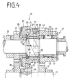
- the one-way clutch 47 can be a one-way clutch of a conventional type with locking bodies 55 guided in a cage 51 and preloaded by a spring ring 53, for example in the form of pawls or pinch rollers. Rolling bearings, which support the casing sleeve 45 on the output shaft 27, are designated by 57 in FIG. 4.
- the drive path of the first gear runs, as shown in FIG. 1 by an arrow 59, from the crankshaft 13 via the starting centrifugal clutch 19, the pinion 31, the gear 33, the sleeve 35, the gears 37, 39 , The intermediate shaft 43, the gears 41, 49, the clamping body 55 to the output shaft 27 and thus to the sprocket 29th
- a manually operable gear change clutch 61 is provided, which, as best shown in FIG. 3 by an arrowed line 63, extends from the gear 33 via the sleeve 35 in one second transmission drive path transmitted torque directly to the output shaft 27 and thus transmits the sprocket 29.
- the output shaft 27 overtakes the jacket sleeve 45 of the one-way clutch 47, which is driven at a lower speed than the one via the gear change clutch 61 with the gearbox clutch 61 due to the drive connection to the sleeve 35 which still exists via the gears 37, 39, 41 and 49 Sleeve 35 coupled output shaft 27.
- the gear change clutch 61 is designed as a friction clutch and comprises a cup-shaped, non-rotatably but axially displaceably guided on a shoulder 65 of the gear 37 coupling member 67 which cooperates with a complementary coupling sleeve 71 which is axially movably coupled to the output shaft 27 via a steep thread.
- the coupling members 67, 71 as best shown in FIG. 4, have frustoconical friction surfaces 73 and 75, respectively, via which a comparatively high friction torque can be transmitted even with a relatively low axial contact force.
- Via a shift fork 77 pivotally mounted in the housing 11, the coupling sleeve 71 can be axially between its engagement point and their disengaging position.
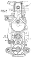
- the shift fork 77 is, as shown in FIG. 2, biased by a leg spring 79 into the disengaging position, from which it can be adjusted against the spring preload towards the clutch element 67 via a Bowden cable or the like, not shown, which engages a lever connected to the shift fork 77 can.
- the turn of the high-helix thread 69 is selected so that the coupling sleeve 71 is screwed from the friction torque transmitted via the friction surface 73, 75 to the coupling member 67, so that there is a self-reinforcing effect of the contact pressure.
- the pitch of the steep thread 69 is dimensioned such that the self-reinforcing effect is sufficient to keep the gear change clutch 61 engaged, even if the shifting force exerted on the lever 81 via the Bowden cable is canceled or the shift mechanism is already in the shift position assigned to the first gear for preselection of the first Gear is moved back into the disengaging position.
- the self-holding effect is only released when the power of the internal combustion engine 1 and thus the torque thereof is reduced to a value by turning back the throttle grip, at which the return force of the leg spring 79 exceeds the self-energizing force of the high-helix thread 69 and moves the shift sleeve 71 into the disengaged position.
- Appropriate coordination of the high-helix thread 69 and the spring force of the leg spring 79 can prevent the speed of the internal combustion engine 1 from being undesirably increased when switching back from second to first gear.
- There is no shift shock during downshifting if the engine speed at which the gear change clutch 61 is disengaged after reduction by the gear wheels 37, 39, 41 and 49 is lower than the speed of the output shaft 27.
- the one-way clutch 47 is still overhauled and only closes the drive path of the first gear by increasing the speed again.
- the coupling sleeve 71 can optionally be slightly braked by the shift fork 77 to reinforce the self-holding effect.
- the coupling member 67 is axially displaceably guided on the extension 65 and is driven by a plate spring 83 to the coupling sleeve 71 against a stop 85 in the form of an annular disk or the like, which is firmly connected to the output shaft 27 biased.
- the plate spring 83 determines the axial force with which the friction surfaces 73, 75 are pressed against one another and increases, starting from an initial value, when the coupling member 67 is lifted axially from the stop 85 in the course of the coupling movement 71.
- the gear change clutch 61 thus engages "softly".
- the maximum stroke of the plate spring 83 is limited by spacers 87, which form an end stop for the coupling sleeve 71 in the engagement position.
- spacers 87 By exchanging spacers 87 of different thicknesses, the maximum stroke 89 of the coupling sleeve 71 and thus the coupling characteristics of the gear change clutch 61 can be adjusted.
- the coupling sleeve 71 is in its disengaged position with a reference surface 91 on a stop plate 93.
- the gearshift sleeve 71 is provided with an axial bore indicated at 95, through which the distance of the spacer disks 87 from the reference surface 91 can be measured with a distance sensor or the like.
- the gears of the transmission 3 including the gear change clutch 61 run in the housing 11 in an oil bath. Due to the cup-shaped shape of the coupling member 67, this forms an annular chamber 97 into which an annular shoulder 99 of the coupling sleeve 71 is immersed in the course of the engagement movement.
- the oil volume displaced when the ring extension 99 is immersed flows out via throttle channels which are provided in the form of grooves 101 in the friction surfaces, for example the friction surface 73. Due to the throttled outflow of the oil from the annular space 97, the engaging movement of the coupling sleeve 71 is braked, as a result of which switching shocks are reduced.
- bores can of course also be provided in the coupling member 67 or the coupling sleeve 71.
- the drive unit further comprises a pedal drive 103, via which the internal combustion engine 1 is started and the two-wheeled motor vehicle is braked on the one hand and can be moved without a motor drive on the other hand.
- the pedal drive 103 comprises a pedal shaft 105 rotatably mounted in the housing 11, at the ends of which pedals, not shown, are attached. On a thread 107 of the pedal shaft 105 sits a coupling sleeve 109 with a complementary thread, which is braked by a leg spring 111 supported on the housing 11.
- the coupling sleeve 109 is rotated with a rotation in the forward direction against a freely rotatable gear 113 which is mounted on the pedal shaft 105 and meshes with a pinion 115 which is fixed on the intermediate shaft 43, or with a rotation in the reverse direction
- Coupling sleeve 109 is screwed against a sleeve 117 which rotatably surrounds the pedal shaft 105 and which, outside of the housing 11, has a lever 119 for actuation gung a rear wheel brake of the vehicle, not shown.
- the pedals When the pedals are actuated in the reverse direction, they act like a coaster brake.
- the pedals drive the pinion 115, the gears 39 and 37 the sprocket 29 via the gear 113. Since the clutch bell 25 of the centrifugal force starting clutch 19 and not its centrifugal weight carrier 17 is driven when the pedal is driven, the internal combustion engine is operated in the bicycle mode of the two-wheel drive. Motor vehicle not driven.
- an engagement device 121 is provided on the centrifugal starting clutch 19, via which the centrifugal clutch 19 can be engaged manually.
- the engagement device 121 comprises, for example, a lever 123 which can be actuated via a Bowden cable and which presses the friction linings 23 against one another via a bell 125 which can be displaced axially relative to the crankshaft 13 and thus the force path of the gearwheel 37 driven by the pedal shaft 105 via the gearwheel 33 and the starting clutch 19 Crankshaft 13 of internal combustion engine 1 closes.
- the pedal shaft is connected to the internal combustion engine via a gear transmission.
- the pedal shaft is connected to the internal combustion engine via a second chain, which is optionally arranged outside the housing 11.
- the pedal shaft expediently also drives the sprocket 29 indirectly via the second chain, the sprocket then being able to be coupled directly to the gear 33 via a second starting clutch to be actuated simultaneously with the engagement device 121.
- the second starter clutch can for example be axially between the sprocket and the Gear 33 can be provided in a receptacle of the housing 11.
- the engagement device 121 and the second starting clutch can be actuated via a Bowden cable with split trousers.
Landscapes
- Engineering & Computer Science (AREA)
- Chemical & Material Sciences (AREA)
- Combustion & Propulsion (AREA)
- Mechanical Engineering (AREA)
- Transportation (AREA)
- General Engineering & Computer Science (AREA)
- One-Way And Automatic Clutches, And Combinations Of Different Clutches (AREA)
- Arrangement Of Transmissions (AREA)
Applications Claiming Priority (2)
| Application Number | Priority Date | Filing Date | Title |
|---|---|---|---|
| DE3725643 | 1987-08-03 | ||
| DE19873725643 DE3725643A1 (de) | 1987-08-03 | 1987-08-03 | Zweigang-stufenschaltgetriebe mit schaltkupplung ohne kraftschlussunterbrechung fuer zweiradfahrzeuge |
Publications (2)
| Publication Number | Publication Date |
|---|---|
| EP0302409A2 true EP0302409A2 (fr) | 1989-02-08 |
| EP0302409A3 EP0302409A3 (fr) | 1990-07-18 |
Family
ID=6332930
Family Applications (1)
| Application Number | Title | Priority Date | Filing Date |
|---|---|---|---|
| EP88112343A Ceased EP0302409A3 (fr) | 1987-08-03 | 1988-07-29 | Unité d'engrenage et d'embrayage pour véhicule à moteur à deux roues |
Country Status (2)
| Country | Link |
|---|---|
| EP (1) | EP0302409A3 (fr) |
| DE (1) | DE3725643A1 (fr) |
Cited By (3)
| Publication number | Priority date | Publication date | Assignee | Title |
|---|---|---|---|---|
| CN102182550A (zh) * | 2011-04-08 | 2011-09-14 | 重庆鑫源摩托车股份有限公司 | 三轮车用发动机 |
| CN102642595A (zh) * | 2012-05-11 | 2012-08-22 | 重庆宗申发动机制造有限公司 | 一种电动车两档变速驱动装置 |
| CN103089933A (zh) * | 2013-01-23 | 2013-05-08 | 重庆隆旺机电有限责任公司 | 不断动力换挡的变速器 |
Families Citing this family (2)
| Publication number | Priority date | Publication date | Assignee | Title |
|---|---|---|---|---|
| US5501310A (en) * | 1993-08-20 | 1996-03-26 | Kabushiki Kaisha Daikin Seisakusho | Motorcycle clutch device |
| US6832590B2 (en) * | 2001-12-25 | 2004-12-21 | Honda Giken Kogyo Kabushiki Kaisha | Internal combustion engine |
Family Cites Families (5)
| Publication number | Priority date | Publication date | Assignee | Title |
|---|---|---|---|---|
| DE7528755U (de) * | 1976-02-05 | Fichtel & Sachs Ag, 8720 Schweinfurt | Selbsttätig schaltendes Wechselgetriebe | |
| DE373612C (de) * | 1923-04-13 | Paul Kaeppler | Reibungskupplung | |
| US4140195A (en) * | 1976-09-08 | 1979-02-20 | Honda Giken Kogyo Kabushiki Kaisha | Power plant for prime mover-equipped bicycles |
| DE3302844A1 (de) * | 1983-01-28 | 1984-08-02 | Fichtel & Sachs Ag, 8720 Schweinfurt | Brennkraftmaschine mit integriertem getriebe zum antrieb eines zweiradfahrzeuges od. dgl. |
| US4545469A (en) * | 1983-05-12 | 1985-10-08 | Yanmar Diesel Engine Co., Ltd. | Cone clutch |
-
1987
- 1987-08-03 DE DE19873725643 patent/DE3725643A1/de not_active Withdrawn
-
1988
- 1988-07-29 EP EP88112343A patent/EP0302409A3/fr not_active Ceased
Cited By (5)
| Publication number | Priority date | Publication date | Assignee | Title |
|---|---|---|---|---|
| CN102182550A (zh) * | 2011-04-08 | 2011-09-14 | 重庆鑫源摩托车股份有限公司 | 三轮车用发动机 |
| CN102182550B (zh) * | 2011-04-08 | 2012-12-26 | 重庆鑫源摩托车股份有限公司 | 三轮车用发动机 |
| CN102642595A (zh) * | 2012-05-11 | 2012-08-22 | 重庆宗申发动机制造有限公司 | 一种电动车两档变速驱动装置 |
| CN102642595B (zh) * | 2012-05-11 | 2013-06-19 | 重庆宗申发动机制造有限公司 | 一种电动车两档变速驱动装置 |
| CN103089933A (zh) * | 2013-01-23 | 2013-05-08 | 重庆隆旺机电有限责任公司 | 不断动力换挡的变速器 |
Also Published As
| Publication number | Publication date |
|---|---|
| DE3725643A1 (de) | 1989-02-23 |
| EP0302409A3 (fr) | 1990-07-18 |
Similar Documents
| Publication | Publication Date | Title |
|---|---|---|
| DE19838146B4 (de) | Kraftübertragungsvorrichtung für ein Fahrzeug | |
| DE69911877T2 (de) | Elektromechanisches Automatgetriebe mit zwei Eingangswellen | |
| DE2944928A1 (de) | Motor-getriebeanordnung fuer fahrzeuge, insbesondere personenkraftfahrzeuge | |
| DE2612021A1 (de) | Zahnraederwechselgetriebe fuer kraftfahrzeuge | |
| DE3906274A1 (de) | Hydraulische vorrichtung fuer ein automatisches getriebe | |
| DE10109662A1 (de) | Verfahren zur Steuerung eines Doppelkupplungsgetriebes | |
| DE2805900C2 (de) | Kraftübertragungseinheit für den Fahrantrieb eines Kraftfahrzeugs | |
| EP3289247B1 (fr) | Dispositif d'assistance au changement de vitesses pour boîte de vitesses et dispositif de changement de vitesses pour motocyclette | |
| DE3233619C2 (de) | Mechanische Schaltvorrichtung für ein Gangwechselgetriebe eines Kraftfahrzeuges mit einem nicht synchronisierten Rückwärtsgang | |
| DE3900403A1 (de) | Startvorrichtung fuer ein automatikgetriebe fuer ein fahrzeug | |
| DE19544352B4 (de) | Fahrzeuggetriebe | |
| DE19910576B4 (de) | Parksperre für ein Schaltgetriebe | |
| EP0710330B1 (fr) | Systeme de changement de vitesses avec dispositif de synchronisation | |
| DE19807374A1 (de) | Getriebe, insbesondere ein Doppelkupplungsgetriebe | |
| DE3527390A1 (de) | Stirnradwechselgetriebe mit einer antriebs- und einer die achsantriebswelle bildenden abtriebswelle, insbesondere fuer personenkraftwagen | |
| EP0723092A1 (fr) | Arrangement de volant-embrayage pour des boîtes de vitesse manuelles synchronisées, spécialement pour véhicules motorisés | |
| EP0302409A2 (fr) | Unité d'engrenage et d'embrayage pour véhicule à moteur à deux roues | |
| DE3729818A1 (de) | Handschaltgetriebe | |
| DE864514C (de) | Wechselgetriebe, insbesondere fuer Kraftfahrzeuge | |
| WO2001065143A1 (fr) | Systeme de transmission a rapports multiples | |
| DE69006962T2 (de) | Getriebe mit ineinander eingreifenden Rädern. | |
| DE3308525A1 (de) | Stufenschaltgetriebe, insbesondere fuer kraftfahrzeuge | |
| DE3918170A1 (de) | Gangschalteinrichtung | |
| DE1505938C (de) | Schaltgetriebe, insbesondere für Mopeds od. dgl | |
| DE921372C (de) | Wechselgetriebe, insbesondere fuer Kraftfahrzeuge, mit hydraulisch geschalteten Reibkupplungen |
Legal Events
| Date | Code | Title | Description |
|---|---|---|---|
| PUAI | Public reference made under article 153(3) epc to a published international application that has entered the european phase |
Free format text: ORIGINAL CODE: 0009012 |
|
| AK | Designated contracting states |
Kind code of ref document: A2 Designated state(s): BE CH DE ES FR LI |
|
| PUAL | Search report despatched |
Free format text: ORIGINAL CODE: 0009013 |
|
| AK | Designated contracting states |
Kind code of ref document: A3 Designated state(s): BE CH DE ES FR LI |
|
| 17P | Request for examination filed |
Effective date: 19901026 |
|
| 17Q | First examination report despatched |
Effective date: 19920330 |
|
| STAA | Information on the status of an ep patent application or granted ep patent |
Free format text: STATUS: THE APPLICATION HAS BEEN REFUSED |
|
| 18R | Application refused |
Effective date: 19920925 |