EP0302444B1 - Anémomètre laser-Doppler - Google Patents
Anémomètre laser-Doppler Download PDFInfo
- Publication number
- EP0302444B1 EP0302444B1 EP19880112527 EP88112527A EP0302444B1 EP 0302444 B1 EP0302444 B1 EP 0302444B1 EP 19880112527 EP19880112527 EP 19880112527 EP 88112527 A EP88112527 A EP 88112527A EP 0302444 B1 EP0302444 B1 EP 0302444B1
- Authority
- EP
- European Patent Office
- Prior art keywords
- laser
- frequency
- doppler
- anemometer
- difference frequency
- Prior art date
- Legal status (The legal status is an assumption and is not a legal conclusion. Google has not performed a legal analysis and makes no representation as to the accuracy of the status listed.)
- Expired - Lifetime
Links
Images

Classifications
-
- G—PHYSICS
- G01—MEASURING; TESTING
- G01P—MEASURING LINEAR OR ANGULAR SPEED, ACCELERATION, DECELERATION, OR SHOCK; INDICATING PRESENCE, ABSENCE, OR DIRECTION, OF MOVEMENT
- G01P5/00—Measuring speed of fluids, e.g. of air stream; Measuring speed of bodies relative to fluids, e.g. of ship, of aircraft
- G01P5/26—Measuring speed of fluids, e.g. of air stream; Measuring speed of bodies relative to fluids, e.g. of ship, of aircraft by measuring the direct influence of the streaming fluid on the properties of a detecting optical wave
Definitions
- the invention relates to a laser Doppler anemometer with two laser diodes, the laser beams of which are concentrated in a specific area of a particle-containing flow of a fluid such that a virtual interference fringe pattern is formed in this area, and with at least one photodetector for detecting fluid flowing through it scattered light, the wavelength of the laser diodes being set and stabilized by temperature and current control.
- Such a laser Doppler anemometer is known from DE-OS 34 35 423.
- the use of laser diodes as a laser light source has the advantage, on the one hand, that a compact and inexpensive construction of the anemometer is possible, on the other hand, the emission wavelength of the laser diode can also be changed by changing the constant current with which the laser diode is operated and / or changing the Set the temperature of the laser diode.
- two partial beams of the same laser diode are superimposed in the area of the flowing fluid to be examined in such a way that a virtual interference fringe pattern is produced. Due to the wavelength stabilization, the interference fringe pattern is of sufficient coherence length the laser radiation is stable and stationary.
- the distance between the intensity maxima in the interference fringe pattern depends on the laser frequency and the intersection angle between the two laser beams.
- the particles of the flowing fluid passing through the interference fringe pattern emit a scattered light, the frequency of which is shifted by the Doppler frequency compared to the frequency of the laser beam.
- the determination of the Doppler frequency enables the flow velocity to be determined. The determination of the flow velocity in this way encounters difficulties when highly turbulent flows and flows with separations are examined and when the flow velocity is very low.
- a laser Doppler anemometer is known in which two laser beams with different frequencies are superimposed so that the interference image moves at a defined speed.
- the use of He-Ne lasers is assumed, but the use of mercury vapor lamps or the like is also considered possible.
- the movement of the interference field should make it possible to measure the actual measured variable, namely the Doppler frequency, with simple means.
- the invention has for its object to provide a laser Doppler anemometer of the type mentioned in such a way that it enables the measurement of the flow rate reliably even at flow speeds with changing signs, for example highly turbulent flows, flows with separations and low flow speeds.
- a virtual interference fringe pattern is created in the cutting volume of the laser beams, which no longer stands still, but moves at a speed corresponding to the difference or beat frequency.
- Such wandering interference fringe patterns have so far been generated by the use of acousto-optical modulators and rotating gratings.
- the disadvantage here is the restriction to a fixed differential frequency in the acousto-optical modulator.
- the frequency shift of the rotating grating is too small in many applications.
- light is lost due to diffraction.
- the invention is based on the knowledge that a wandering interference fringe system can be produced without the disadvantages mentioned by means of two wavelength-adjustable laser diodes.
- the field of application of laser diode anemometers is considerably expanded, so that additional examination possibilities are opened up.
- the laser diodes can work continuously or in pulsed mode. However, use in continuous operation is preferred.
- the use of two separate laser diodes has the additional advantage that a higher laser power is available in the measurement volume, so that a favorable signal-to-noise ratio can be achieved.
- the Doppler frequency containing the information of interest about the fluid velocity is superimposed on the difference frequency (shift frequency).
- the evaluation of this measurement signal therefore requires some effort.
- the evaluation will generally also presuppose that the laser beams of the laser diode frequency are stabilized, so that the control effort for stabilizing the laser beams of the laser diodes is not insignificant.
- a simple evaluation of the measurement signal is also possible with less well stabilized laser beam frequencies of the laser diodes if a signal corresponding to the difference frequency is mixed with a signal corresponding to the scattered light, so that the Doppler frequency is directly available after filtering.
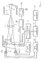
- two laser diodes LD1 and LD2 are aligned in such a way that their beams 1, 2 overlap in the measurement volume in the flow 3 of a fluid and form a virtual interference fringe pattern.
- the two laser beams 1, 2 each pass through focusing optics 4, which ensure that the laser beams 1, 2 are each focused in the measurement volume.
- the two laser beams 1, 2 are absorbed in a beam trap 5, so that they do not interfere with the further measurement.
- the light scattered backwards from the measurement volume is focused with a focusing lens L1 onto the input of a photodetector D1.
- the photodetector D1 converts the optical signal into an electrical signal, which is evaluated in a known manner with respect to the Doppler frequency - and thus the flow velocity of the flow 3 of the fluid.
- the focusing lens L1 has through openings 6 for the laser beams 1, 2, so that they are not influenced by the focusing lens L1.
- a broadband detector 8 converts the optical signal at its input into an electrical signal.
- the broadband detector is followed by a signal processing unit 9, which consists of a frequency divider and a frequency-voltage converter. A voltage proportional to the difference frequency between the two laser beams 1, 2 is thus present at the output of the signal processing unit 9 - and thus at an input of a downstream comparator 10.
- a reference voltage set with a reference voltage source 11 arrives at a second input of the comparator 10.
- the two laser diodes LD1 and LD2 are each connected in a manner known per se to a control network 12, 13 with which the current I1 or I2 flowing through the laser diodes LD1 or LD2 is set and kept constant, and the working temperature T1 or T2 of the laser diodes LD1 or LD2 is also kept constant.
- the comparator (controller) 10 is designed in the present case so that it enables control of the constant current I2 of the laser diode LD2 if the difference frequency measured with the broadband detector 8 between the two laser beams 1, 2 deviates from the target frequency set with the aid of the reference voltage source 11 .
- the output signal of the photodetector 1 contains the superimposed Doppler frequency f D and the difference frequency (shift frequency) f S.
- this signal reaches an input of a mixer 14, on the other input of which the output signal of the broadband detector D2 8 arrives.
- the field of application of laser diode anemometers is considerably expanded, so that additional examination possibilities are opened up.
- the laser diodes can work continuously or in pulsed mode. However, use in continuous operation is preferred.
Landscapes
- Engineering & Computer Science (AREA)
- Multimedia (AREA)
- Aviation & Aerospace Engineering (AREA)
- Physics & Mathematics (AREA)
- General Physics & Mathematics (AREA)
- Optical Radar Systems And Details Thereof (AREA)
Claims (4)
- Anémomètre Doppler laser comportant deux diodes laser (LD1, LD2) dont les rayonnements laser (1, 2) sont concentrés dans une zone déterminée d'un écoulement (3) d'un fluide contenant des particules de telle manière qu'un motif virtuel de franges d'interférence ce forme dans cette zone, et comportant au moins un photodétecteur (D1) pour détecter la lumière diffusée par le fluide en écoulement, la longueur d'onde des diodes laser (LD1, LD2) étant réglée et stabilisée par une régulation de température et de courant (12, 13), caractérisé en ce que les deux diodes laser (LD1, LD2) sont réglées sur des longueurs d'onde d'émission différentes et en ce qu'un circuit de régulation (8, 9, 10) est prévu pour maintenir constante la fréquence différentielle et agit sur la régulation de température et/ou de courant (13) d'au moins une des diodes laser (LD1, LD2).
- Anémomètre Doppler laser selon la revendication 1, caractérisé en ce qu'un signal de mesure correspondant à la fréquence différentielle est appliqué à une entrée d'un comparateur (10) à la seconde entrée duquel est appliqué un signal de référence réglé selon la fréquence différentielle désirée.
- Anémomètre Doppler laser selon la revendication 1, caractérisé en ce qu'un signal correspondant à la fréquence différentielle (fs) est mélangé à un signal (fs + fD), correspondant à la lumière diffusée, de sorte que la fréquence Doppler (fD) peut être obtenue directement après filtrage.
- Anémomètre Doppler laser selon la revendication 3, caractérisé en ce que le signal de sortie (fD + fs) de la photodiode (D1) et le signal de sortie (fs) du dispositif (8) de mesure de la fréquence différentielle sont appliqués à un mélangeur (14) à la sortie duquel est relié un filtre (15) pour la fréquence Doppler (fD).
Applications Claiming Priority (4)
| Application Number | Priority Date | Filing Date | Title |
|---|---|---|---|
| DE3735978 | 1987-08-05 | ||
| DE19873735978 DE3735978A1 (de) | 1986-10-25 | 1987-10-23 | Synchronisierungsvorrichtung fuer ein synchroneingriffsgetriebe |
| DE19873736772 DE3736772A1 (de) | 1987-08-05 | 1987-10-30 | Laser-doppler-anemometer |
| DE3736772 | 1987-10-30 |
Publications (3)
| Publication Number | Publication Date |
|---|---|
| EP0302444A2 EP0302444A2 (fr) | 1989-02-08 |
| EP0302444A3 EP0302444A3 (en) | 1989-11-02 |
| EP0302444B1 true EP0302444B1 (fr) | 1991-11-13 |
Family
ID=25861063
Family Applications (1)
| Application Number | Title | Priority Date | Filing Date |
|---|---|---|---|
| EP19880112527 Expired - Lifetime EP0302444B1 (fr) | 1987-08-05 | 1988-08-02 | Anémomètre laser-Doppler |
Country Status (1)
| Country | Link |
|---|---|
| EP (1) | EP0302444B1 (fr) |
Families Citing this family (4)
| Publication number | Priority date | Publication date | Assignee | Title |
|---|---|---|---|---|
| DE3936950C2 (de) * | 1988-07-08 | 1996-12-19 | Deutsch Franz Forsch Inst | Laser-Doppler-Anemometer |
| DE69031577T2 (de) * | 1989-03-31 | 1998-04-16 | Canon Kk | Doppler-Geschwindigkeitsmesser |
| US5216478A (en) * | 1989-03-31 | 1993-06-01 | Canon Kabushiki Kaisha | Doppler velocity meter |
| JP2801360B2 (ja) * | 1990-05-21 | 1998-09-21 | キヤノン株式会社 | ドツプラ速度計 |
Family Cites Families (2)
| Publication number | Priority date | Publication date | Assignee | Title |
|---|---|---|---|---|
| DE2430664A1 (de) * | 1974-06-26 | 1976-01-22 | Philips Patentverwaltung | Laser-doppler-anemometer |
| DE3435423A1 (de) * | 1984-02-21 | 1985-08-22 | Bundesrepublik Deutschland, vertreten durch den Bundesminister für Wirtschaft, dieser vertreten durch den Präsidenten der Physikalisch-Technischen Bundesanstalt, 3300 Braunschweig | Laser-doppler-anemometer |
-
1988
- 1988-08-02 EP EP19880112527 patent/EP0302444B1/fr not_active Expired - Lifetime
Also Published As
| Publication number | Publication date |
|---|---|
| EP0302444A2 (fr) | 1989-02-08 |
| EP0302444A3 (en) | 1989-11-02 |
Similar Documents
| Publication | Publication Date | Title |
|---|---|---|
| DE69026791T2 (de) | Verfahren und Vorrichtung zur Messung der Teilchengrössenverteilung | |
| DE69126506T2 (de) | Gerät zur Verschiebung- oder Geschwindigkeit- Messung | |
| EP0152916B1 (fr) | Anémomètre laser-doppler | |
| DE2058064A1 (de) | Geraet zur Bestimmung der Zusammensetzung einer Substanz durch eine optische Strahlung | |
| DE3937851A1 (de) | Laser-doppler-geschwindigkeitsmesser | |
| EP0074609B1 (fr) | Dispositif de mesure de vitesse de rotation | |
| DE3736772A1 (de) | Laser-doppler-anemometer | |
| EP0333905A1 (fr) | Anémomètre laser-doppler pour la mesure de la vitesse d'objets mobiles | |
| DE69528948T2 (de) | Verschiebungsinformationsmessgerät | |
| CH689335A5 (de) | Verfahren und Anemometer zur Auswertung von Laser-Doppler-Signalen. | |
| DE4400680C2 (de) | Vorrichtung zur Bestimmung von Abstandsänderungen eines Objekts | |
| EP0302444B1 (fr) | Anémomètre laser-Doppler | |
| DE69529033T2 (de) | Optisches Gerät zur Detektion einer Verschiebung | |
| DE19537647C1 (de) | Verfahren und Anordnung zur Messung physikalischer Größen von lichtstreuenden bewegten Teilchen mittels eines Laser-Doppler-Anemometers | |
| DE69119296T2 (de) | Dopplergeschwindigkeitsmesser und Gerät unter Verwendung desselben | |
| WO1993005364A1 (fr) | Detecteur optique pour mouvements de rotation | |
| EP0467127A2 (fr) | Procédé et dispositif pour la détection optique et l'évaluation de signaux de lumière diffusée | |
| DE3441088C2 (fr) | ||
| WO2023020876A1 (fr) | Système laser de mesure de distance et procédé de mesure de distance | |
| DE3042622C2 (de) | Vorrichtung zur Überwachung der Geschwindigkeit und des Durchsatzes von Strömungen | |
| DE3725978C1 (en) | Laser Doppler anemometer | |
| DE3337135A1 (de) | Kollisionsverhinderungssystem fuer fahrzeuge | |
| EP0303156A2 (fr) | Procédé pour anémomètrie laser-doppler | |
| EP0185358B1 (fr) | Dispositif de mesure de la vitesse de rotation | |
| DE2043290A1 (de) | Verfahren zur Geschwindigkeitsmessung in Strömungsfeldern mittels einer selbstjustierenden, für den Empfang rückwärts gestreuter Signale dienenden Laser-Dopplersonde |
Legal Events
| Date | Code | Title | Description |
|---|---|---|---|
| PUAI | Public reference made under article 153(3) epc to a published international application that has entered the european phase |
Free format text: ORIGINAL CODE: 0009012 |
|
| AK | Designated contracting states |
Kind code of ref document: A2 Designated state(s): DE FR GB IT NL |
|
| PUAL | Search report despatched |
Free format text: ORIGINAL CODE: 0009013 |
|
| AK | Designated contracting states |
Kind code of ref document: A3 Designated state(s): DE FR GB IT NL |
|
| 17P | Request for examination filed |
Effective date: 19890929 |
|
| 17Q | First examination report despatched |
Effective date: 19910121 |
|
| GRAA | (expected) grant |
Free format text: ORIGINAL CODE: 0009210 |
|
| AK | Designated contracting states |
Kind code of ref document: B1 Designated state(s): DE FR GB IT NL |
|
| ET | Fr: translation filed | ||
| GBT | Gb: translation of ep patent filed (gb section 77(6)(a)/1977) | ||
| REF | Corresponds to: |
Ref document number: 3866185 Country of ref document: DE Date of ref document: 19911219 |
|
| ITF | It: translation for a ep patent filed | ||
| PLBE | No opposition filed within time limit |
Free format text: ORIGINAL CODE: 0009261 |
|
| STAA | Information on the status of an ep patent application or granted ep patent |
Free format text: STATUS: NO OPPOSITION FILED WITHIN TIME LIMIT |
|
| 26N | No opposition filed | ||
| PGFP | Annual fee paid to national office [announced via postgrant information from national office to epo] |
Ref country code: GB Payment date: 19960724 Year of fee payment: 9 |
|
| PGFP | Annual fee paid to national office [announced via postgrant information from national office to epo] |
Ref country code: DE Payment date: 19960801 Year of fee payment: 9 |
|
| PGFP | Annual fee paid to national office [announced via postgrant information from national office to epo] |
Ref country code: FR Payment date: 19960823 Year of fee payment: 9 |
|
| PGFP | Annual fee paid to national office [announced via postgrant information from national office to epo] |
Ref country code: NL Payment date: 19960831 Year of fee payment: 9 |
|
| PG25 | Lapsed in a contracting state [announced via postgrant information from national office to epo] |
Ref country code: GB Free format text: LAPSE BECAUSE OF NON-PAYMENT OF DUE FEES Effective date: 19970802 |
|
| PG25 | Lapsed in a contracting state [announced via postgrant information from national office to epo] |
Ref country code: NL Free format text: LAPSE BECAUSE OF NON-PAYMENT OF DUE FEES Effective date: 19980301 |
|
| GBPC | Gb: european patent ceased through non-payment of renewal fee |
Effective date: 19970802 |
|
| PG25 | Lapsed in a contracting state [announced via postgrant information from national office to epo] |
Ref country code: FR Free format text: LAPSE BECAUSE OF NON-PAYMENT OF DUE FEES Effective date: 19980430 |
|
| PG25 | Lapsed in a contracting state [announced via postgrant information from national office to epo] |
Ref country code: DE Free format text: LAPSE BECAUSE OF NON-PAYMENT OF DUE FEES Effective date: 19980501 |
|
| NLV4 | Nl: lapsed or anulled due to non-payment of the annual fee |
Effective date: 19980301 |
|
| REG | Reference to a national code |
Ref country code: FR Ref legal event code: ST |
|
| PG25 | Lapsed in a contracting state [announced via postgrant information from national office to epo] |
Ref country code: IT Free format text: LAPSE BECAUSE OF NON-PAYMENT OF DUE FEES;WARNING: LAPSES OF ITALIAN PATENTS WITH EFFECTIVE DATE BEFORE 2007 MAY HAVE OCCURRED AT ANY TIME BEFORE 2007. THE CORRECT EFFECTIVE DATE MAY BE DIFFERENT FROM THE ONE RECORDED. Effective date: 20050802 |