EP0302502A2 - Disposition pour connecter un répétiteur pour un câble de mer - Google Patents
Disposition pour connecter un répétiteur pour un câble de mer Download PDFInfo
- Publication number
- EP0302502A2 EP0302502A2 EP88112732A EP88112732A EP0302502A2 EP 0302502 A2 EP0302502 A2 EP 0302502A2 EP 88112732 A EP88112732 A EP 88112732A EP 88112732 A EP88112732 A EP 88112732A EP 0302502 A2 EP0302502 A2 EP 0302502A2
- Authority
- EP
- European Patent Office
- Prior art keywords
- arrangement according
- nsk
- umbilical cord
- cable
- main cable
- Prior art date
- Legal status (The legal status is an assumption and is not a legal conclusion. Google has not performed a legal analysis and makes no representation as to the accuracy of the status listed.)
- Withdrawn
Links
Images

Classifications
-
- H—ELECTRICITY
- H02—GENERATION; CONVERSION OR DISTRIBUTION OF ELECTRIC POWER
- H02G—INSTALLATION OF ELECTRIC CABLES OR LINES, OR OF COMBINED OPTICAL AND ELECTRIC CABLES OR LINES
- H02G15/00—Cable fittings
- H02G15/08—Cable junctions
- H02G15/10—Cable junctions protected by boxes, e.g. by distribution, connection or junction boxes
- H02G15/12—Cable junctions protected by boxes, e.g. by distribution, connection or junction boxes for incorporating transformers, loading coils or amplifiers
- H02G15/14—Cable junctions protected by boxes, e.g. by distribution, connection or junction boxes for incorporating transformers, loading coils or amplifiers specially adapted for submarine cables
-
- G—PHYSICS
- G02—OPTICS
- G02B—OPTICAL ELEMENTS, SYSTEMS OR APPARATUS
- G02B6/00—Light guides; Structural details of arrangements comprising light guides and other optical elements, e.g. couplings
- G02B6/44—Mechanical structures for providing tensile strength and external protection for fibres, e.g. optical transmission cables
- G02B6/4439—Auxiliary devices
- G02B6/444—Systems or boxes with surplus lengths
- G02B6/4441—Boxes
- G02B6/4448—Electro-optic
-
- G—PHYSICS
- G02—OPTICS
- G02B—OPTICAL ELEMENTS, SYSTEMS OR APPARATUS
- G02B6/00—Light guides; Structural details of arrangements comprising light guides and other optical elements, e.g. couplings
- G02B6/44—Mechanical structures for providing tensile strength and external protection for fibres, e.g. optical transmission cables
- G02B6/4439—Auxiliary devices
- G02B6/4471—Terminating devices ; Cable clamps
- G02B6/4472—Manifolds
- G02B6/4475—Manifolds with provision for lateral branching
-
- H—ELECTRICITY
- H02—GENERATION; CONVERSION OR DISTRIBUTION OF ELECTRIC POWER
- H02G—INSTALLATION OF ELECTRIC CABLES OR LINES, OR OF COMBINED OPTICAL AND ELECTRIC CABLES OR LINES
- H02G9/00—Installations of electric cables or lines in or on the ground or water
- H02G9/02—Installations of electric cables or lines in or on the ground or water laid directly in or on the ground, river-bed or sea-bottom; Coverings therefor, e.g. tile
-
- H—ELECTRICITY
- H04—ELECTRIC COMMUNICATION TECHNIQUE
- H04B—TRANSMISSION
- H04B3/00—Line transmission systems
- H04B3/02—Details
- H04B3/36—Repeater circuits
Definitions
- the invention relates to an arrangement for connecting an intermediate amplifier for submarine cables, in which the intermediate amplifier is looped into the signal lines of a main cable and connected to supply lines.
- the previous submarine cable technology provides partially flexible, pressure-resistant sleeve housings for these repeaters, which are spliced into the submarine cable to be supplied with tensile strength, pressure resistance and with suitable insulation for the power conductor (supply line).
- This technology which has remained unchanged for years, has the advantage of being able to lay the repeater and cable as a unit, but the serious disadvantage of having to lift the repeater together with the cable running on the seabed when repairs are required.
- the invention has for its object to make a repeater located on the sea floor easily accessible for maintenance and repair purposes.
- the repeater Since the repeater is not integrated directly into the main cable or spliced into it, but is looped into an umbilical cord branching off from the main cable via a connecting link, the repeater can be lifted for maintenance purposes without having to lift the main cable. Since the main cable remains on the sea floor, maintenance work on the repeater can be carried out simply by lifting the umbilical cord.
- the amplifier housing has an arbitrarily designed pot-like shape. This enables a simpler construction of the repeater independent of the dimensions of the main cable.
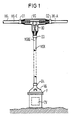
- FIG. 1 shows a submarine cable SK connected to a connecting element VG, and an umbilical cord cable NSK branching off from this connecting element VG, to the end of which a pot-like pressure-resistant amplifier housing VG containing the intermediate amplifier ZV is fastened.
- the link VG is as flat pull and pressure resistant branch sleeve, in particular in the form of a T-link. Connecting the HK main cable to a tensile and pressure-resistant T housing is easier than with a spliced-in flexible sleeve, since the pure connecting sleeve is short and can therefore be kept rigid. It is possible to use a rigid T-shaped housing and pour it out pressure-tight.
- the two openings 01 and 02 of the branch sleeve lying in one axis accommodate the main cable entry HK-E and the main cable exit HK-A of the main cable HK.
- the opening 03 lying transversely or obliquely to this axis serves to hold one end NSKE of the umbilical cord cable NSK in a tension-resistant manner.
- the coupling of the main cable HK and the umbilical cord NSK to the branch sleeve is also carried out in such a way that there is an impermeability to the surrounding medium, in particular water.
- the sealed ends HK-E, HK-A and NSKE of the HK main cable and the umbilical cord NSK, which run into the branch sleeve, are freed from their outer protective sheath within the branch sleeve.
- the signal and supply lines of the main cable entrance HK-E are redirected into the umbilical cord cable NSK via a bolt BO located in the middle of the branch sleeve and through this to the intermediate amplifier ZV.
- the outgoing signal and supply lines pass through the umbilical cord cable NKS and reach the main cable outlet HK-A in the branch sleeve after being guided via the central bolt BO.
- the umbilical cord cable NSK thus contains all incoming and outgoing signal and supply lines, ie the light signal and the supply current pass through it twice. If a current transformer is placed in the branch sleeve, the amount of copper and insulation in the umbilical cord can be greatly reduced.
- the amplifier housing VG protecting the intermediate amplifier ZV can be designed as a pressure-resistant pot of any design, which hardly needs to adapt to the dimensions of the umbilical cord cable NSK. In this way, the construction of the intermediate amplifier ZV is considerably simplified since no shape-determining housings have to be used.
- the end of the umbilical cord cable NSK, which runs into the amplifier housing VG, is tensile and pressure-resistant and water-impermeable sig connected to the input opening 04 of the amplifier housing VG.
- the sealed amplifier housing has a central opening flange F so that the repeater can be easily exposed during maintenance and repair work.
- the length of the NSK umbilical cord cable which is designed as a special tensile cable, corresponds at least to the greatest installation depth that occurs.
- the cross section of the supply lines running in the umbilical cord cable NSK can be smaller than that running in the main cable HK, since the length of the umbilical cord cable NSK is at most 7500 m.
- FIG. 2 shows a possibility of laying the arrangement of the main cable HK according to the invention and the umbilical cord cable NSK connected via the connecting member VB with a connected intermediate amplifier ZV.
- the procedure is such that the main cable HK with the connecting member VG is moved through the laying device VV (caterpillar).
- the intermediate amplifier ZV with the umbilical cord NSK is left on the base floor GP without the laying ship VS traveling.
- the laying ship VS resumes its journey for further laying the main cable HK. It is advisable to attach an auxiliary rope HS to the amplifier housing VG, the length of which corresponds approximately to the laying depth.
- a floating marker can be attached to the far end of the auxiliary rope HS, which makes it easier to locate the intermediate amplifier ZV.
- a buoyant buoy can advantageously be used as a marker, depending on the length of the auxiliary rope HS it can be found above or below water. This arrangement makes it easy to find the repeater ZV and the repeater ZV can be lifted for maintenance purposes without having to lift the main cable HK.
Landscapes
- Physics & Mathematics (AREA)
- Engineering & Computer Science (AREA)
- General Physics & Mathematics (AREA)
- Optics & Photonics (AREA)
- Computer Networks & Wireless Communication (AREA)
- Signal Processing (AREA)
- Power Engineering (AREA)
- Cable Accessories (AREA)
- Cable Transmission Systems, Equalization Of Radio And Reduction Of Echo (AREA)
Applications Claiming Priority (2)
| Application Number | Priority Date | Filing Date | Title |
|---|---|---|---|
| DE3726358 | 1987-08-07 | ||
| DE3726358 | 1987-08-07 |
Publications (2)
| Publication Number | Publication Date |
|---|---|
| EP0302502A2 true EP0302502A2 (fr) | 1989-02-08 |
| EP0302502A3 EP0302502A3 (fr) | 1990-10-10 |
Family
ID=6333324
Family Applications (1)
| Application Number | Title | Priority Date | Filing Date |
|---|---|---|---|
| EP19880112732 Withdrawn EP0302502A3 (fr) | 1987-08-07 | 1988-08-04 | Disposition pour connecter un répétiteur pour un câble de mer |
Country Status (3)
| Country | Link |
|---|---|
| US (1) | US4841103A (fr) |
| EP (1) | EP0302502A3 (fr) |
| DK (1) | DK441388A (fr) |
Cited By (2)
| Publication number | Priority date | Publication date | Assignee | Title |
|---|---|---|---|---|
| US6236789B1 (en) | 1999-12-22 | 2001-05-22 | Pirelli Cables And Systems Llc | Composite cable for access networks |
| CN108182991A (zh) * | 2018-01-20 | 2018-06-19 | 上海禹海科技有限公司 | 一种水下hdpe脐带缆穿舱密封工艺 |
Families Citing this family (3)
| Publication number | Priority date | Publication date | Assignee | Title |
|---|---|---|---|---|
| JPH0787013A (ja) * | 1993-09-10 | 1995-03-31 | Fujitsu Ltd | 光海底ケーブルシステム |
| DE19957405A1 (de) * | 1999-11-29 | 2001-06-13 | Nkt Cables Gmbh | Anordnung von Lichtwellenleiterelementen und Spleißgehäuse für Lichtwellenleiterelemente |
| FR3065120B1 (fr) * | 2017-04-10 | 2019-06-21 | Dcns Energies | Systeme de raccordement de cables sous-marins |
Family Cites Families (7)
| Publication number | Priority date | Publication date | Assignee | Title |
|---|---|---|---|---|
| FR710230A (fr) * | 1930-12-31 | 1931-08-20 | Firme Felten & Guilleaume Carl | Poste de renforcement intermédiaire pour câbles de plat fond servant à l'enregistrement à longue distance |
| US2155650A (en) * | 1937-11-10 | 1939-04-25 | Bell Telephone Labor Inc | Housing for repeater apparatus |
| FR857989A (fr) * | 1938-07-20 | 1940-11-13 | Fides Gmbh | Système de transmission, composé d'un câble coaxial et d'amplificateurs |
| US2551417A (en) * | 1946-06-27 | 1951-05-01 | Standard Oil Dev Co | Apparatus for seismic exploration |
| US3270312A (en) * | 1964-03-31 | 1966-08-30 | Hazeltine Research Inc | Cable splice |
| US3923121A (en) * | 1970-09-25 | 1975-12-02 | Texas Instruments Inc | Towed land cable |
| US3866162A (en) * | 1973-03-15 | 1975-02-11 | Mark Products | Geophone takeout assembly for seismic cables |
-
1988
- 1988-08-01 US US07/226,881 patent/US4841103A/en not_active Expired - Fee Related
- 1988-08-04 EP EP19880112732 patent/EP0302502A3/fr not_active Withdrawn
- 1988-08-05 DK DK441388A patent/DK441388A/da not_active Application Discontinuation
Cited By (4)
| Publication number | Priority date | Publication date | Assignee | Title |
|---|---|---|---|---|
| US6236789B1 (en) | 1999-12-22 | 2001-05-22 | Pirelli Cables And Systems Llc | Composite cable for access networks |
| EP1290482A4 (fr) * | 1999-12-22 | 2003-04-02 | Pirelli Cables & Systems Llc | Cable composite pour reseaux d'acces |
| CN108182991A (zh) * | 2018-01-20 | 2018-06-19 | 上海禹海科技有限公司 | 一种水下hdpe脐带缆穿舱密封工艺 |
| CN108182991B (zh) * | 2018-01-20 | 2019-06-14 | 上海禹海科技有限公司 | 一种水下hdpe脐带缆穿舱密封工艺 |
Also Published As
| Publication number | Publication date |
|---|---|
| DK441388A (da) | 1989-02-08 |
| US4841103A (en) | 1989-06-20 |
| EP0302502A3 (fr) | 1990-10-10 |
| DK441388D0 (da) | 1988-08-05 |
Similar Documents
| Publication | Publication Date | Title |
|---|---|---|
| DE69102924T2 (de) | Inspektionssystem für eine Rohrleitung. | |
| DE4140701C1 (en) | Buried container e.g. for fibre=optic cable junction - is partially held in shaft and has removable lid and lifting arrangement to allow easy working access e.g. for further splicing | |
| EP0859257A1 (fr) | Dispositif pour le branchement d'un câble de télécommunications contenant plusieurs éléments de câblage comportant des fibres optiques | |
| EP0082280B1 (fr) | Système de refrigération pour des dispositifs de communication à grande puissance dissipée | |
| DE29722107U1 (de) | Vorrichtung zum Einführen und/oder Herausführen eines Kabels in eine bzw. aus einer rohrförmigen Leitung | |
| EP0302502A2 (fr) | Disposition pour connecter un répétiteur pour un câble de mer | |
| DE3525723A1 (de) | Unterwasserleitung fuer nachrichtenuebertragung mittels optischer fasern | |
| DE3937693C2 (fr) | ||
| DE1959738C3 (de) | Vorrichtung zum einziehen bzw herausziehen von elastischen versorgungsleitungen in ein bzw aus einem schutzrohr | |
| DE19636162B4 (de) | Verbindungskabel mit mindestens einem Lichtwellenleiter mit endseitig angeordneten Anschlußelementen | |
| DE19734274B4 (de) | Kommunikationsnetz mit Lichtwellenleitern zwischen Teilnehmern und Kommunikationzentralen in bestehenden Versorgungsleitungen | |
| DE3001226A1 (de) | Leitungsnetz zum uebertragen von signalen | |
| EP0875777A2 (fr) | Manchon de câble pour câble à guide d'ondes optiques | |
| DE2838577A1 (de) | Strangfoermiger koerper mit hoher zugfestigkeit | |
| EP0499106A1 (fr) | Procédé et dispositif de filer et de haler de l'ombilicale d'un dispositif sous-marin | |
| DE4227410C1 (de) | Freiluft-endverschluss fuer lichtwellenleiter-phasenseile (lps). | |
| DE3247803A1 (de) | Elektrooptische verbindungseinrichtung | |
| DE2651080C2 (de) | Verbindungs- oder Aufteilungsmuffe für Lichtleitfasern und -kabel | |
| DE3106661C2 (de) | Anordnung zum Orten eines metallfreien Kabels | |
| DE4315681C1 (de) | Kabelverzweiger | |
| DE3701788A1 (de) | Seekabel-uebertragungsstrecke mit optischen uebertragungselementen | |
| DE19741433B4 (de) | Mikrokabel, bestehend aus einem Rohr und darin längsverlaufend eingebrachten Lichtwellenleitern | |
| DE3624653C2 (de) | Optischer Biegekoppler mit Prüfstift, insbesondere für eine Vielzahl von Lichtwellenleitern | |
| DE3905090A1 (de) | Aufschiebbare garnitur fuer kunststoffisolierte mittelspannungskabel mit integrierten lichtwellenleitern | |
| DE3417636A1 (de) | Endverbinder oder spleissvorrichtung zum endverbinden, abspannen oder spleissen eines zum schleppen von luft/wassergeschuetzen hinter einem seismischen wasserfahrzeug verwendeten kabels |
Legal Events
| Date | Code | Title | Description |
|---|---|---|---|
| PUAI | Public reference made under article 153(3) epc to a published international application that has entered the european phase |
Free format text: ORIGINAL CODE: 0009012 |
|
| AK | Designated contracting states |
Kind code of ref document: A2 Designated state(s): BE DE FR GB IT NL SE |
|
| PUAL | Search report despatched |
Free format text: ORIGINAL CODE: 0009013 |
|
| AK | Designated contracting states |
Kind code of ref document: A3 Designated state(s): BE DE FR GB IT NL SE |
|
| 17P | Request for examination filed |
Effective date: 19901126 |
|
| 17Q | First examination report despatched |
Effective date: 19921002 |
|
| STAA | Information on the status of an ep patent application or granted ep patent |
Free format text: STATUS: THE APPLICATION IS DEEMED TO BE WITHDRAWN |
|
| 18D | Application deemed to be withdrawn |
Effective date: 19930213 |