EP0302538B1 - High-capacity physical and/or chemical treatment apparatus in an automatic product production plant - Google Patents
High-capacity physical and/or chemical treatment apparatus in an automatic product production plant Download PDFInfo
- Publication number
- EP0302538B1 EP0302538B1 EP88201312A EP88201312A EP0302538B1 EP 0302538 B1 EP0302538 B1 EP 0302538B1 EP 88201312 A EP88201312 A EP 88201312A EP 88201312 A EP88201312 A EP 88201312A EP 0302538 B1 EP0302538 B1 EP 0302538B1
- Authority
- EP
- European Patent Office
- Prior art keywords
- modular supports
- stacks
- cylindrical container
- modular
- container
- Prior art date
- Legal status (The legal status is an assumption and is not a legal conclusion. Google has not performed a legal analysis and makes no representation as to the accuracy of the status listed.)
- Expired - Lifetime
Links
- 238000004519 manufacturing process Methods 0.000 title claims abstract description 15
- 239000000126 substance Substances 0.000 title claims abstract description 11
- 238000003860 storage Methods 0.000 claims abstract description 8
- 239000000463 material Substances 0.000 claims description 4
- 239000011159 matrix material Substances 0.000 claims description 2
- 239000002184 metal Substances 0.000 claims description 2
- 239000002991 molded plastic Substances 0.000 claims 1
- 235000013305 food Nutrition 0.000 abstract description 2
- 238000011144 upstream manufacturing Methods 0.000 abstract description 2
- 230000003750 conditioning effect Effects 0.000 description 13
- 238000004806 packaging method and process Methods 0.000 description 9
- 238000000034 method Methods 0.000 description 4
- 230000008569 process Effects 0.000 description 3
- 230000008901 benefit Effects 0.000 description 2
- 238000003780 insertion Methods 0.000 description 2
- 230000037431 insertion Effects 0.000 description 2
- 230000014759 maintenance of location Effects 0.000 description 2
- 238000000465 moulding Methods 0.000 description 2
- 229920003023 plastic Polymers 0.000 description 2
- 239000004033 plastic Substances 0.000 description 2
- 239000004698 Polyethylene Substances 0.000 description 1
- 230000009471 action Effects 0.000 description 1
- 230000008859 change Effects 0.000 description 1
- 230000001143 conditioned effect Effects 0.000 description 1
- 238000007599 discharging Methods 0.000 description 1
- 230000000694 effects Effects 0.000 description 1
- 238000002156 mixing Methods 0.000 description 1
- -1 polyethylene Polymers 0.000 description 1
- 229920000573 polyethylene Polymers 0.000 description 1
- 238000003825 pressing Methods 0.000 description 1
- 238000009423 ventilation Methods 0.000 description 1
Images


Classifications
-
- B—PERFORMING OPERATIONS; TRANSPORTING
- B65—CONVEYING; PACKING; STORING; HANDLING THIN OR FILAMENTARY MATERIAL
- B65G—TRANSPORT OR STORAGE DEVICES, e.g. CONVEYORS FOR LOADING OR TIPPING, SHOP CONVEYOR SYSTEMS OR PNEUMATIC TUBE CONVEYORS
- B65G47/00—Article or material-handling devices associated with conveyors; Methods employing such devices
- B65G47/34—Devices for discharging articles or materials from conveyor
- B65G47/46—Devices for discharging articles or materials from conveyor and distributing, e.g. automatically, to desired points
- B65G47/51—Devices for discharging articles or materials from conveyor and distributing, e.g. automatically, to desired points according to unprogrammed signals, e.g. influenced by supply situation at destination
- B65G47/5104—Devices for discharging articles or materials from conveyor and distributing, e.g. automatically, to desired points according to unprogrammed signals, e.g. influenced by supply situation at destination for articles
-
- B—PERFORMING OPERATIONS; TRANSPORTING
- B65—CONVEYING; PACKING; STORING; HANDLING THIN OR FILAMENTARY MATERIAL
- B65G—TRANSPORT OR STORAGE DEVICES, e.g. CONVEYORS FOR LOADING OR TIPPING, SHOP CONVEYOR SYSTEMS OR PNEUMATIC TUBE CONVEYORS
- B65G21/00—Supporting or protective framework or housings for endless load-carriers or traction elements of belt or chain conveyors
- B65G21/16—Supporting or protective framework or housings for endless load-carriers or traction elements of belt or chain conveyors for conveyors having endless load-carriers movable in curved paths
- B65G21/18—Supporting or protective framework or housings for endless load-carriers or traction elements of belt or chain conveyors for conveyors having endless load-carriers movable in curved paths in three-dimensionally curved paths
-
- B—PERFORMING OPERATIONS; TRANSPORTING
- B65—CONVEYING; PACKING; STORING; HANDLING THIN OR FILAMENTARY MATERIAL
- B65G—TRANSPORT OR STORAGE DEVICES, e.g. CONVEYORS FOR LOADING OR TIPPING, SHOP CONVEYOR SYSTEMS OR PNEUMATIC TUBE CONVEYORS
- B65G47/00—Article or material-handling devices associated with conveyors; Methods employing such devices
- B65G47/34—Devices for discharging articles or materials from conveyor
- B65G47/46—Devices for discharging articles or materials from conveyor and distributing, e.g. automatically, to desired points
- B65G47/51—Devices for discharging articles or materials from conveyor and distributing, e.g. automatically, to desired points according to unprogrammed signals, e.g. influenced by supply situation at destination
- B65G47/5104—Devices for discharging articles or materials from conveyor and distributing, e.g. automatically, to desired points according to unprogrammed signals, e.g. influenced by supply situation at destination for articles
- B65G47/515—First In-Last Out systems [FILO]; Last In-First Out systems [LIFO]
- B65G47/5177—First In-Last Out systems [FILO]; Last In-First Out systems [LIFO] using rotary conveyor(s)
-
- B—PERFORMING OPERATIONS; TRANSPORTING
- B65—CONVEYING; PACKING; STORING; HANDLING THIN OR FILAMENTARY MATERIAL
- B65G—TRANSPORT OR STORAGE DEVICES, e.g. CONVEYORS FOR LOADING OR TIPPING, SHOP CONVEYOR SYSTEMS OR PNEUMATIC TUBE CONVEYORS
- B65G2207/00—Indexing codes relating to constructional details, configuration and additional features of a handling device, e.g. Conveyors
- B65G2207/24—Helical or spiral conveying path
Definitions
- This invention relates to a high-capacity physical and/or chemical treatment apparatus in an automatic product production plant.
- Production plants or lines are known comprising in succession a plurality of apparatuses or sections which provide for the complete treatment of a product for example starting from the mixing of the various components and proceeding through a series of predetermined steps to the packaging or boxing of the product.
- An example of such a plant is illustrated in Italian patent No. IT-A-1.209.627 in the name of the present applicant.
- Such a plant maintains properly ordered product arrangement during the entire production process by using modular supports so as to make any rearranging machine unnecessary, but it has certain limits in spite of a certain degree of flexibility attainable using said modular supports.
- the device used for conveying the products through such an apparatus for example a conditioning tunnel
- a conditioning tunnel is generally of the so-called "endless” type, in which the products are moved in succession one behind the other by entrainment elements such as chains, conveyors and/or pushers.
- An object of the present invention is to provide a physical and/or chemical treatment apparatus which by utilizing the advantages of modular supports for the product is able to obviate plant hold-ups by absorbing any stoppages of the various devices downstream of said treatment apparatus so as to ensure continuity of operation of the machines upstream of the packaging zone.
- a high-capacity physical and/or chemical treatment apparatus in an automatic product production plant in which modular supports are used to accompany the products along the plant and through said treatment apparatus, characterised in that said modular supports are loaded within said apparatus into at least one cylindrical rotary storage container divided into radial loading sectors, each sector comprising a plurality of parallel guides positioned in superposed planes, there being provided at an inlet end (12) of said apparatus a stacking device for forming stacks of modular supports to be loaded into said at least one cylindrical container and, in correspondence with an exit end of said apparatus, a device able to receive one of said stacks of loaded modular supports and to dismantle said one stack and feed the modular supports in succession onto a conveyor means, pusher devices being associated with said stacking device and with said at least one cylindrical container to transfer said stacks of modular supports into the next device in said apparatus.
- a buffer or storage zone is created within said apparatus to hold a number of modular supports excessive to those normally present within the tunnel and undergoing the conditioning process.
- This object is attained by increasing the number of radial sectors of the rotary cylinder beyond those required on average for production. These sectors, which are of such a number as to provide a sufficient buffer area calculated on the basis of the typical hold-ups of the plant to be constructed, are normally on stand-by, but when the packaging plant is not operating the tunnel can continue to be fed with stacks of modular supports using the empty sectors until the packaging plant resumes normal operation or until the buffer area is full.
- said treatment apparatus also comprises a central microprocessor arranged to operationally correlate said devices in accordance with a time law predetermined on the basis of the products of said stacks under treatment and to optimise the operation of that fraction of the rotary cylinder sectors which define the buffer zone.
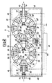
- a physical and/or chemical treatment apparatus according to the present invention, indicated overall by 11 and represented for example by a conditioning tunnel for food products, is included in an automatic plant (not shown) for the production of products.
- the tunnel 11 is provided with an inlet opening 12 and an outlet opening 13 through which a series of modular supports 16 shown in Figures 3 and 4 are conveyed on respective conveyor means 14 and 15.
- Each modular support 16 in the form of a tray, is constructed for example of a plastics material such as polyethylene by moulding, and comprises a series of holes 17 or seats defined and distributed in accordance with a matrix arrangement to receive containers for single products indicated diagrammatically at 18 or supported products.
- the holes 17, which in the example are shown circular, are used to house and to keep in ordered arrangement containers of the most varied type such as cones, cups etc., and can equally be of any shape.
- the modular support 16 can be constructed not only by moulding plastics material but by pressing metal, cardboard or any other material suitable for the physical and/or chemical treatment to which it is subjected.
- the longer opposing sides of the modular support 16 are provided at their ends with tapered portions 19 or bevelled corners to facilitate their insertion into position.
- a vertical stacking device 20 arranged to receive the modular supports 16 from the conveyor means 14 and to position them one above the other in respective support planes 21 defined by guides formed from section bars so as to effect an initial storage and deposit and to form a stack.
- a suitable vertically extending pusher device 22 associated frontwards with the stacking device 20 and for example having an articulated parallelogram structure loads the plurality of modular supports 16 onto a first cylindrical rotary storage container 23.
- the cylindrical storage container 23 comprises an annular base 24 composed of section bars on which there are disposed vertical uprigths 25 which together with lower and upper endpieces 26 of essentially triangular shape define and form radial loading sectors 27.
- Each sector 27 is provided with a plurality of suitable pairs of parallel guides 28 formed of L-shaped sections and rigid with the vertical uprights 25, they being disposed in pairs one above the other in superposed planes to define a position for the modular supports 16 pushed by the respective pusher device 22 from the stacking device 21 so as to form stacks of modular supports.
- Providing a plurality of guides 28 disposed a vertical distance apart equal to the minimum height of a product 18 not only enables modular supports containing minimum-height products to be positioned in each of them but also makes it possible to receive modular supports containing higher products by selective insertion of the supports (such as one on every third guide, etc).
- Rotating elements such as wheels 29 are rigid with the base 24 to enable the cylindrical container 23 to rotate on a floor 30.
- Horizontal rollers 31 fixed to the floor 30 act as guides for a circumferential shoe element 32 which is also horizontal and rigid with base 24.
- Sprocket toothed ring 33 extends radially on the outside of the base 24 and cooperates with a chain 34 driven by a sprocket wheel 35 connected to a drive unit 36 in order to rotate the cylindrical container 23.
- annular element 38 Rigid with the top of the inner structure 37 of the tunnel 11 there extends downwards an annular element 38 also carrying horizontal guide rollers 31 which cooperate with a further annular circumferential shoe element 32 to aid proper rotation of the cylindrical container 23.
- a second pusher device 39 identical to the preceding, which moves the plurality of modular supports 16 previously positioned in a sector 27 towards a second cylindrical container 40.
- the second cylindrical container 40 is structured in a similar manner to the first cylindrical container 23 and equivalent components are indicated by the same reference numerals followed by a prime (24′, 25′, etc.).
- a pusher device 39′ is also positioned within said second cylindrical container 40 and acts on the modular product supports 16 contained in a sector 27′ to push them towards a device 41 acting as a stack dismantling and evacuation means able to receive one of said stacks of modular supports at a time and to dismantle said stack and feed said supports in succession onto the second conveyor means 15 aligned with the outlet opening 13 of the conditioning tunnel 11.
- centering elements indicated schematically by 42 are used to correctly align the pusher devices 22, 39 and 39′ with the individual sectors 27, 27′ concerned and with the stacking device 20 and 41.
- the rotation of the two cylindrical containers 23 and 40 which can be continuous or follow a predetermined law, and is mutually independent, is maintained until either a new plurality or stack of modular supports 16 is ready on the stacking device 20 or one of said pluralities disposed in a sector 27, 27′ has to be moved to another cylindrical container or discharged onto the evacuation device 41.
- the stacking device 20 is used to form stacks of modular supports 16 to be loaded, while the evacuation device 41 disposed at the outlet end of said apparatus receives one at a time said stacks of modular supports loaded into a sector of one of said cylindrical container and dismantles said stack to feed the modular supports in succession onto a second conveyor means 15.
- a series of connecting lines 44 connects to the microprocessor 43 the various drive means for the conveyors, pushers, stacking device and cylindrical containers, all the devices for correct mutual positioning, ie the centering elements 42, and the inlet and outlet sensors 46.
- free surfaces indicated by dashed and dotted lines 45 located around the cylindrical containers 23, 40 which must be at least one in number, but can be of any number within the treatment apparatus, form positioning zones for auxiliary treatment devices such as evaporators, fans etc. according to the process to be carried out.
- the operating cycle commences when the modular supports 16 or trays arriving from the filling line (not shown) are fed by the first conveyor means 14 to the stacking device 20 where they are stacked in the required number on the support planer 21.
- the appropriate pusher device 22 can be used to position it within an empty sector 27 of the first cylindrical container 23, which has been halted in the correct position because of the presence of the centering elements 42.
- this container begins to rotate about its axis to allow good ventilation of the product to be conditioned.
- the rotation determined by the drive unit 36, continues for example until the next stack of modular supports 16 has been completed on the stacking device 20.
- the microprocessor 43 which controls all the functions of the entire plant and thus also the treatment apparatus 11 according to the invention, determines the correct stoppage of an empty sector 27 of the cylindrical container 23 at the loading zone for the modular supports 16 or rather of the stacking device 20.
- this container is halted by the microprocessor 43 so that by means of further centering elements 42 the sector 27′ lies opposite the evacuation device 41 so that a further third pusher device 39′, also disposed within the second cylindrical container 40, discharges said stack of modular supports 16 ready for packaging.
- the second conveyor means 15 Conveying to the packaging line is provided by the second conveyor means 15 which receives the individual modular supports 16 from the evacuation device 41 and feeds them in succession one after another towards the exit opening 13 of the conditioning tunnel 11.
- the first cylindrical container 23, the second cylindrical container 40 and any other cylindrical container, if present, operate in accordance with a time relationship determined by the logic of the microprocessor 43 which automatically starts the rotation, and controls the positioning, the transfer, the loading and unloading in the correct empty or full sectors 27, 27′. This takes place for example in accordance with the particular requirements of the product or products to be treated.
- the apparatus according to the invention attains the object of making the feed independent of the discharges and of creating a storage or buffer zone which provides continuity of production and operation as the more common hold-ups can be absorbed by it.
- each cylindrical container receives and transfers stacks of trays not mechanically and repetitively but dynamically by using the most convenient empty sector and discharging those stacks which have undergone treatment onto the evacuation device. These operations take place in accordance with a time relationship controlled by the microprocessor, which causes a stack of trays to be discharged only after the time required for conditioning an individual stack of trays has expired.
- each cylindrical container can rotate continuously for an indeterminate time and thus undergo a fraction of a revolution or one or more revolutions, until either a new stack is presented to the feed end or a stack which undergone its conditioning process is ready for evacuation. Such rotation also facilitates optimum homogeneous physical and/or chemical treatment.
Landscapes
- Engineering & Computer Science (AREA)
- Mechanical Engineering (AREA)
- Specific Conveyance Elements (AREA)
- General Preparation And Processing Of Foods (AREA)
- Agricultural Chemicals And Associated Chemicals (AREA)
- Attitude Control For Articles On Conveyors (AREA)
- Control And Other Processes For Unpacking Of Materials (AREA)
- Supplying Of Containers To The Packaging Station (AREA)
- Food Preservation Except Freezing, Refrigeration, And Drying (AREA)
- Warehouses Or Storage Devices (AREA)
Priority Applications (1)
| Application Number | Priority Date | Filing Date | Title |
|---|---|---|---|
| AT88201312T ATE69143T1 (de) | 1987-07-21 | 1988-06-27 | Hochkapazitaets-apparat fuer physikalische und/oder chemische behandlung in einer automatischen produkt-herstellungsanlage. |
Applications Claiming Priority (2)
| Application Number | Priority Date | Filing Date | Title |
|---|---|---|---|
| IT21367/87A IT1222083B (it) | 1987-07-21 | 1987-07-21 | Apparecchiatura di trattamento fisico e/o chimico ad elevata potenzialita' in un impianto automatico per la produzione di prodotti |
| IT2136787 | 1987-07-21 |
Publications (2)
| Publication Number | Publication Date |
|---|---|
| EP0302538A1 EP0302538A1 (en) | 1989-02-08 |
| EP0302538B1 true EP0302538B1 (en) | 1991-11-06 |
Family
ID=11180748
Family Applications (1)
| Application Number | Title | Priority Date | Filing Date |
|---|---|---|---|
| EP88201312A Expired - Lifetime EP0302538B1 (en) | 1987-07-21 | 1988-06-27 | High-capacity physical and/or chemical treatment apparatus in an automatic product production plant |
Country Status (9)
| Country | Link |
|---|---|
| US (1) | US4890718A (es) |
| EP (1) | EP0302538B1 (es) |
| AT (1) | ATE69143T1 (es) |
| CA (1) | CA1298232C (es) |
| DE (1) | DE3866053D1 (es) |
| DK (1) | DK174230B1 (es) |
| ES (1) | ES2026997T3 (es) |
| GR (1) | GR3003154T3 (es) |
| IT (1) | IT1222083B (es) |
Families Citing this family (13)
| Publication number | Priority date | Publication date | Assignee | Title |
|---|---|---|---|---|
| CH679035A5 (es) * | 1989-08-09 | 1991-12-13 | Daverio Ag | |
| US5065872A (en) * | 1990-10-05 | 1991-11-19 | White Storage & Retrieval Systems, Inc. | Dual access storage and retrieval system |
| DE4135241C1 (es) * | 1991-10-25 | 1993-05-13 | Kloeckner Haensel Gmbh, 3000 Hannover, De | |
| IT1260039B (it) * | 1992-02-24 | 1996-03-28 | Metodo di transito per piccoli oggetti all'interno di camere di trattamento, e suoi mezzi attuatori | |
| IT1263471B (it) * | 1993-03-24 | 1996-08-05 | Sasib Spa | Dispositivo per trasformare una successione casuale di confezioni unitarie in una successione ordinata, uniforme delle stesse. |
| US5337880A (en) * | 1993-07-23 | 1994-08-16 | Automated Systems, Inc. | Article storage carousel with automatic conveyor loading and unloading |
| DE59503969D1 (de) * | 1994-05-25 | 1998-11-26 | Sig Pack Sytems Ag | Transport-Gruppier- und Speichervorrichtung |
| DE69808603T2 (de) * | 1997-03-20 | 2003-07-10 | Siemens Ag | Drehspeicher und verfahren zu seiner handhabung |
| DE19712023A1 (de) * | 1997-03-21 | 1998-09-24 | Strasser Maschinenbau Gmbh | Transporteinrichtung |
| FR2789374B1 (fr) * | 1999-02-08 | 2001-03-23 | Andre Zalkin & Cie Ets | Dispositif d'accumulation dynamique d'objets |
| CA2389436A1 (en) * | 2002-06-06 | 2003-12-06 | Serguei Goussev | Multi-level conveying apparatus and method |
| EP2445003A1 (en) * | 2010-10-25 | 2012-04-25 | Applied Materials, Inc. | Apparatus for providing a rotation carrier magazine, and method of operating thereof |
| CN109732552B (zh) * | 2018-12-28 | 2021-01-29 | 王珍珍 | 一种电容器切脚的回收料盒 |
Family Cites Families (9)
| Publication number | Priority date | Publication date | Assignee | Title |
|---|---|---|---|---|
| US3068987A (en) * | 1962-12-18 | Conveyor system | ||
| US1595439A (en) * | 1925-01-19 | 1926-08-10 | Wilson James Elliott | Preparation of dough for the making of bread |
| NL6404364A (es) * | 1964-04-21 | 1965-10-22 | ||
| US3324786A (en) * | 1964-11-13 | 1967-06-13 | Alwyn E Geiser | Grape cooler and field packer |
| US3584750A (en) * | 1969-02-15 | 1971-06-15 | Baker Perkins Inc | Farinaceous product handling system |
| US3831293A (en) * | 1972-09-15 | 1974-08-27 | Baker Perkins Inc | Stacked tray processing and freezing system |
| DE2817732B2 (de) * | 1978-04-22 | 1981-01-08 | Transport- Und Foerderanlagen-Gmbh, Spezialmaschinenfabrik Lauda, 6970 Lauda | Vorrichtung zum automatischen Be- und Entladen eines mehretagigen Speichergerüstes mit keramischen Formungen, z.B. Ziegeln |
| US4525978A (en) * | 1981-09-17 | 1985-07-02 | Mitsubishi Jukogyo Kabushiki Kaisha | Sterilizing system for filled and sealed articles |
| DE3442161A1 (de) * | 1984-11-17 | 1986-05-28 | C. Keller GmbH u. Co KG, 4530 Ibbenbüren | Einrichtung zum umladen von auf unterlagen angeordneten keramischen formlingen |
-
1987
- 1987-07-21 IT IT21367/87A patent/IT1222083B/it active
-
1988
- 1988-06-27 DE DE8888201312T patent/DE3866053D1/de not_active Expired - Lifetime
- 1988-06-27 ES ES198888201312T patent/ES2026997T3/es not_active Expired - Lifetime
- 1988-06-27 AT AT88201312T patent/ATE69143T1/de not_active IP Right Cessation
- 1988-06-27 EP EP88201312A patent/EP0302538B1/en not_active Expired - Lifetime
- 1988-06-29 CA CA000570702A patent/CA1298232C/en not_active Expired - Lifetime
- 1988-07-01 US US07/214,414 patent/US4890718A/en not_active Expired - Lifetime
- 1988-07-20 DK DK198804055A patent/DK174230B1/da not_active IP Right Cessation
-
1991
- 1991-11-19 GR GR91401779T patent/GR3003154T3/el unknown
Also Published As
| Publication number | Publication date |
|---|---|
| DK405588A (da) | 1989-01-22 |
| ES2026997T3 (es) | 1992-05-16 |
| ATE69143T1 (de) | 1991-11-15 |
| CA1298232C (en) | 1992-03-31 |
| US4890718A (en) | 1990-01-02 |
| IT8721367A0 (it) | 1987-07-21 |
| DE3866053D1 (de) | 1991-12-12 |
| IT1222083B (it) | 1990-08-31 |
| DK405588D0 (da) | 1988-07-20 |
| EP0302538A1 (en) | 1989-02-08 |
| DK174230B1 (da) | 2002-10-07 |
| GR3003154T3 (en) | 1993-02-17 |
Similar Documents
| Publication | Publication Date | Title |
|---|---|---|
| EP0302538B1 (en) | High-capacity physical and/or chemical treatment apparatus in an automatic product production plant | |
| US6286290B1 (en) | Conveyor apparatus for depositing products in groups into containers | |
| SU856373A3 (ru) | Автоматическа упаковочна лини | |
| EP2650240B1 (en) | Apparatus and method for buffering products | |
| JP2609296B2 (ja) | 包装機械の搬送装置へ物品を移送する装置 | |
| US4955794A (en) | Apparatus for forming and conveying groups of flat stacked items | |
| EP2473409B1 (en) | Continuous filling device | |
| WO2010125441A1 (en) | Apparatus and method for cutting slices of a food product and loading them on a conveying surface, and treatment plant including said apparatus | |
| US6769856B2 (en) | Plant for unloading stacks of thermoformed objects from a receiving cage to a removing conveyer | |
| CN110816964A (zh) | 细小瓶子输送装置及工作方法 | |
| US5807055A (en) | Apparatus for loading and/or unloading a container with stacks of packages, such as for instance egg trays | |
| JPH05139422A (ja) | 物品供給装置 | |
| CN115072056B (zh) | 一种条包自动集料系统 | |
| EP0317198A2 (en) | Packaging systems and packaging processes | |
| KR100231621B1 (ko) | 층상화된 섬유소 제품, 특히 원면 패드용 처리장치 | |
| US5353916A (en) | Conveyer apparatus | |
| JPH11179295A (ja) | 鶏卵等の物品の選別装置 | |
| US5187919A (en) | Process for filling containers with products in a predetermined distribution | |
| US3189160A (en) | Roller bed conveyor | |
| US3633733A (en) | Article-handling apparatus | |
| JP2000025939A (ja) | 長物農産物の供給装置 | |
| EP0099593A2 (en) | Machine for arranging product units, for example rigid or deformable packages | |
| EP0036241A1 (en) | Method and arrangement for conveying groups of cubes from a moulding press through a conditioning device | |
| JPH0811826A (ja) | 鶏卵選別装置及びその鶏卵選別装置を採用する鶏卵選別包装装置 | |
| JPH0426321Y2 (es) |
Legal Events
| Date | Code | Title | Description |
|---|---|---|---|
| PUAI | Public reference made under article 153(3) epc to a published international application that has entered the european phase |
Free format text: ORIGINAL CODE: 0009012 |
|
| AK | Designated contracting states |
Kind code of ref document: A1 Designated state(s): AT BE CH DE ES FR GB GR LI LU NL SE |
|
| 17P | Request for examination filed |
Effective date: 19890616 |
|
| 17Q | First examination report despatched |
Effective date: 19901102 |
|
| GRAA | (expected) grant |
Free format text: ORIGINAL CODE: 0009210 |
|
| AK | Designated contracting states |
Kind code of ref document: B1 Designated state(s): AT BE CH DE ES FR GB GR LI LU NL SE |
|
| REF | Corresponds to: |
Ref document number: 69143 Country of ref document: AT Date of ref document: 19911115 Kind code of ref document: T |
|
| REF | Corresponds to: |
Ref document number: 3866053 Country of ref document: DE Date of ref document: 19911212 |
|
| ET | Fr: translation filed | ||
| REG | Reference to a national code |
Ref country code: ES Ref legal event code: FG2A Ref document number: 2026997 Country of ref document: ES Kind code of ref document: T3 |
|
| PLBE | No opposition filed within time limit |
Free format text: ORIGINAL CODE: 0009261 |
|
| STAA | Information on the status of an ep patent application or granted ep patent |
Free format text: STATUS: NO OPPOSITION FILED WITHIN TIME LIMIT |
|
| 26N | No opposition filed | ||
| REG | Reference to a national code |
Ref country code: GR Ref legal event code: FG4A Free format text: 3003154 |
|
| EPTA | Lu: last paid annual fee | ||
| EAL | Se: european patent in force in sweden |
Ref document number: 88201312.1 |
|
| REG | Reference to a national code |
Ref country code: GB Ref legal event code: IF02 |
|
| PGFP | Annual fee paid to national office [announced via postgrant information from national office to epo] |
Ref country code: GR Payment date: 20050524 Year of fee payment: 18 |
|
| PGFP | Annual fee paid to national office [announced via postgrant information from national office to epo] |
Ref country code: NL Payment date: 20050605 Year of fee payment: 18 |
|
| PGFP | Annual fee paid to national office [announced via postgrant information from national office to epo] |
Ref country code: AT Payment date: 20050613 Year of fee payment: 18 |
|
| PGFP | Annual fee paid to national office [announced via postgrant information from national office to epo] |
Ref country code: CH Payment date: 20050629 Year of fee payment: 18 |
|
| PGFP | Annual fee paid to national office [announced via postgrant information from national office to epo] |
Ref country code: LU Payment date: 20050705 Year of fee payment: 18 |
|
| PGFP | Annual fee paid to national office [announced via postgrant information from national office to epo] |
Ref country code: ES Payment date: 20050728 Year of fee payment: 18 |
|
| PGFP | Annual fee paid to national office [announced via postgrant information from national office to epo] |
Ref country code: BE Payment date: 20050817 Year of fee payment: 18 |
|
| PG25 | Lapsed in a contracting state [announced via postgrant information from national office to epo] |
Ref country code: AT Free format text: LAPSE BECAUSE OF NON-PAYMENT OF DUE FEES Effective date: 20060627 |
|
| PG25 | Lapsed in a contracting state [announced via postgrant information from national office to epo] |
Ref country code: ES Free format text: LAPSE BECAUSE OF NON-PAYMENT OF DUE FEES Effective date: 20060628 |
|
| PG25 | Lapsed in a contracting state [announced via postgrant information from national office to epo] |
Ref country code: LI Free format text: LAPSE BECAUSE OF NON-PAYMENT OF DUE FEES Effective date: 20060630 Ref country code: BE Free format text: LAPSE BECAUSE OF NON-PAYMENT OF DUE FEES Effective date: 20060630 Ref country code: CH Free format text: LAPSE BECAUSE OF NON-PAYMENT OF DUE FEES Effective date: 20060630 |
|
| PG25 | Lapsed in a contracting state [announced via postgrant information from national office to epo] |
Ref country code: NL Free format text: LAPSE BECAUSE OF NON-PAYMENT OF DUE FEES Effective date: 20070101 |
|
| REG | Reference to a national code |
Ref country code: CH Ref legal event code: PL |
|
| NLV4 | Nl: lapsed or anulled due to non-payment of the annual fee |
Effective date: 20070101 |
|
| PGFP | Annual fee paid to national office [announced via postgrant information from national office to epo] |
Ref country code: SE Payment date: 20070607 Year of fee payment: 20 |
|
| PGFP | Annual fee paid to national office [announced via postgrant information from national office to epo] |
Ref country code: DE Payment date: 20070621 Year of fee payment: 20 |
|
| REG | Reference to a national code |
Ref country code: ES Ref legal event code: FD2A Effective date: 20060628 |
|
| PGFP | Annual fee paid to national office [announced via postgrant information from national office to epo] |
Ref country code: GB Payment date: 20070627 Year of fee payment: 20 |
|
| BERE | Be: lapsed |
Owner name: *VORTEX SYSTEMS S.R.L. Effective date: 20060630 |
|
| PGFP | Annual fee paid to national office [announced via postgrant information from national office to epo] |
Ref country code: FR Payment date: 20070608 Year of fee payment: 20 |
|
| REG | Reference to a national code |
Ref country code: GB Ref legal event code: PE20 Expiry date: 20080626 |
|
| PG25 | Lapsed in a contracting state [announced via postgrant information from national office to epo] |
Ref country code: LU Free format text: LAPSE BECAUSE OF NON-PAYMENT OF DUE FEES Effective date: 20060627 |
|
| EUG | Se: european patent has lapsed | ||
| PG25 | Lapsed in a contracting state [announced via postgrant information from national office to epo] |
Ref country code: GR Free format text: LAPSE BECAUSE OF NON-PAYMENT OF DUE FEES Effective date: 20070104 |
|
| PG25 | Lapsed in a contracting state [announced via postgrant information from national office to epo] |
Ref country code: GB Free format text: LAPSE BECAUSE OF EXPIRATION OF PROTECTION Effective date: 20080626 |