EP0302549A2 - Boîtier d'emmagasinage pour un support d'information en forme de disque - Google Patents
Boîtier d'emmagasinage pour un support d'information en forme de disque Download PDFInfo
- Publication number
- EP0302549A2 EP0302549A2 EP88201575A EP88201575A EP0302549A2 EP 0302549 A2 EP0302549 A2 EP 0302549A2 EP 88201575 A EP88201575 A EP 88201575A EP 88201575 A EP88201575 A EP 88201575A EP 0302549 A2 EP0302549 A2 EP 0302549A2
- Authority
- EP
- European Patent Office
- Prior art keywords
- tray
- information carrier
- cover part
- holder
- basic position
- Prior art date
- Legal status (The legal status is an assumption and is not a legal conclusion. Google has not performed a legal analysis and makes no representation as to the accuracy of the status listed.)
- Withdrawn
Links
- 239000000969 carrier Substances 0.000 description 4
- 230000037431 insertion Effects 0.000 description 1
- 238000003780 insertion Methods 0.000 description 1
- 238000004806 packaging method and process Methods 0.000 description 1
- 229920003023 plastic Polymers 0.000 description 1
- 238000006748 scratching Methods 0.000 description 1
- 230000002393 scratching effect Effects 0.000 description 1
- 230000035939 shock Effects 0.000 description 1
Images

Classifications
-
- G—PHYSICS
- G11—INFORMATION STORAGE
- G11B—INFORMATION STORAGE BASED ON RELATIVE MOVEMENT BETWEEN RECORD CARRIER AND TRANSDUCER
- G11B17/00—Guiding record carriers not specifically of filamentary or web form, or of supports therefor
- G11B17/22—Guiding record carriers not specifically of filamentary or web form, or of supports therefor from random access magazine of disc records
-
- G—PHYSICS
- G11—INFORMATION STORAGE
- G11B—INFORMATION STORAGE BASED ON RELATIVE MOVEMENT BETWEEN RECORD CARRIER AND TRANSDUCER
- G11B33/00—Constructional parts, details or accessories not provided for in the other groups of this subclass
- G11B33/02—Cabinets; Cases; Stands; Disposition of apparatus therein or thereon
- G11B33/04—Cabinets; Cases; Stands; Disposition of apparatus therein or thereon modified to store record carriers
- G11B33/0405—Cabinets; Cases; Stands; Disposition of apparatus therein or thereon modified to store record carriers for storing discs
- G11B33/0411—Single disc boxes
- G11B33/0422—Single disc boxes for discs without cartridge
Definitions
- the invention relates to a storage cassette with a bottom part, a hinged lid part and a tray which can be inserted into the bottom part for receiving an insertable plate-shaped information carrier which can be held on the tray by means of at least three holders provided on the tray, at least one of which is supported on its outer edge Bracket is designed to be movable and in its basic position presses the information carrier under spring force against the other brackets and fixes it in its position.
- An element for receiving and holding a rigid circular information plate consists of a tray to be inserted into a storage cassette with a receiving trough which has holders for fixing the information plate.
- the brackets act opposite each other on the edge of an inserted Information plate. At least one of these brackets is resilient.
- the tray has a double function, namely to hold the information plate while it is being stored in the storage cassette, and it additionally enables the information plate to be transferred from the cassette into the playback device without contact. If necessary, however, the disc can also be removed from the tray by hand and inserted into the player.
- the resilient holder can spring back in the event of vibrations in such a way that the plate-shaped information carrier is released. This is undesirable since in this case the information carrier can flip back and forth in the packaging and be damaged.
- At least one locking element is provided on the cover part, which locks the resilient holder in its basic position when the cover is closed.
- Such a locking element provided on the cover part prevents the movable and resilient holder from springing back. This also applies to mechanical shocks. Characterized in that the locking element is provided on the cover part, the resilient holder is automatically locked in its basic position when the cover part is closed on the base part. Nevertheless, if the cover part is open, removal of the plate-shaped information carrier is possible, if desired, by manually moving the resilient holder out of its basic position, so that the plate-shaped information carrier is released.
- the locking element is advantageously arranged such that it does not exert any force on the resilient holder as long as it is in its basic position. This ensures that no additional forces are exerted on an inserted plate-shaped information carrier, which could lead to twisting thereof.
- the locking element can be produced economically, since only a corresponding device is to be provided on the cover part, which can be injected together with the cover part and thus requires almost no additional effort.
- the locking element on the cover part Has the form of a locking lug, which engages behind the movable holder in the closed state of the cover so that it cannot be moved from its basic position.
- a locking element according to the invention can now advantageously be attached to the cover part in such a way that it engages behind the movable holder so that it cannot be moved out of its basic position.
- a locking lug is provided on the cover part, which engages behind the movable holder when the cover is closed. It is thus safely avoided in a simple manner that when the cover is closed, that is to say, for example during transport, the movable holder can move back from the basic position and release an inserted plate-shaped information carrier.
- Another advantage of such an arrangement is that no additional measures for securing the transport are required on the tray or on the movable holder attached to the tray. Rather, it is sufficient to provide a locking lug on the cover part in the form described above.
- a handle strip is provided on the insertable tray in the region of the axis of rotation of the cover part and that the movable holder on the tray and the locking lug on the cover part are arranged in the region of the handle bar.
- a grip strip is often provided on trays of the type described at the outset for receiving plate-shaped information carriers. If both the handle bar on the tray and the movable holder are arranged in such a way that they are arranged in the region of the axis of rotation of the cover part, the locking lug is also arranged in the area of the handle bar.
- the advantage here is that the locking lug is arranged in an area of the cover part in which it does not interfere. This is important because a device, for example for receiving a text booklet, is often provided in the cover part. If the locking lug is provided in the area of the axis of rotation of the cover part, the insertion of such a text booklet is not hindered.
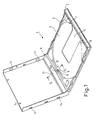
- a storage cassette shown in Fig. 1 is used to hold and store plate-shaped information carriers, in particular optically readable information carriers, such as a compact disc.
- the storage cassette 1 has a base part 2 and a foldable cover part 3. Both the bottom part 2 and the cover part 3 usually consist of a transparent plastic.
- the cover part 3 is rotatably connected to the bottom part 2.
- a tray 4 is inserted for receiving a plate-shaped information carrier.
- This tray 4 is used to hold an information carrier (not shown in the figure).
- the tray 4 has a circular recess 5 into which the information carrier can be inserted.
- a grip bar 6 is arranged on one side next to the tub 5. This grip strip 6 is located in the region of the axis of rotation of the cover part 3 which is hingedly mounted on the base part.
- brackets In order to fix a plate-shaped information carrier (not shown in FIG. 1) inserted into the tub 5, three brackets are provided on the edge of the tub 5, which hold an inserted information carrier on its outer edge.
- Two brackets 7 and 8 are arranged opposite the handle bar 6 on the outer edge of the tub 5. These brackets 7 and 8 are designed to be immobile. The brackets 7 and 8 are in such a distance from each other that an inserted information carrier can move back and forth as little as possible.
- a third bracket 9 is located opposite the brackets 7 and 8, that is to say in the region of the handle bar 6 on the edge of the tub 5.
- the bracket 9 In contrast to the brackets 7 and 8, the bracket 9 is designed to be movable.
- the holder 9 is provided on a leaf spring 10.
- an information plate (not shown in the figure) is clamped between the holders 7, 8 and 9.
- the bracket 9 can be moved back from its basic position by springing back of the leaf spring 10, so that an information carrier clamped between the brackets 7, 8 and 9 can be removed from the tub 5.
- Such removal can either be done manually, by moving the leaf spring 10 and the holder 9 back manually, or else automatically in one device.
- the entire tray 4 together with an inserted information carrier and fixed between the holders 7, 8 and 9 is inserted into a playback device.
- the leaf spring 10 and thus also the holder 9 are then moved back by a device to be provided accordingly, so that the inserted plate-shaped information carrier is released and can be played.
- a recess 11 is provided in the tub 5, which allows a plate-shaped information carrier inserted into the tub 5 to be scanned from below, for example by means of a laser beam.
- a locking lug 12 is provided on the cover part 3 in the region of its axis of rotation on the base part 2.
- This locking lug 12 protrudes approximately vertically from the cover part 3 and is arranged thereon so that it engages behind the holder 9 on the leaf spring 9 when the cover 3 is closed.
- a recess 11 is provided behind the bracket 10 in the leaf spring 10, in which the locking lug 12 can engage.
- the locking lug 12 is thus arranged so that they engage in this recess 12 when a plate-shaped information carrier is clamped between the brackets 7, 8 and 9 in the tub 5. The holder 9 is then locked in this basic position and remains when it acts on it Forces in this position.
- the locking lug 12 since it is provided on the cover part, does not in any way hinder the normal operation of the tray, i.e. an inserted information carrier can still be removed from the tray 5 of the tray 4 both manually and mechanically in a corresponding player.
- the locking lug 12 is provided in the region of the axis of rotation of the cover part, inserting a text booklet (not shown in the figure) into the cover part 3 is not hindered.
- 3 receptacles 14 are provided on the side walls of the cover part, behind which a text booklet can be pushed.
- FIG. 2 shows a section of the storage cassette shown in FIG. 1 together with the inserted tray 4 in section along the line II-II.
- FIG. 2 shows the base part 2 with the cover part 3 opened with a tray 4 inserted in the base part 2.
- a plate-shaped information carrier 21 is inserted into the tray 4.
- the plate-shaped information carrier 21 is fixed behind the movable holder 9.
- the holder 9 is provided on the leaf spring 10, which has a tongue 10a pointing in the direction of the grip bar 6.
- a recess 11 is provided in this tongue 10a of the leaf spring 10.
- the holder 9 is shown in its basic position. In this basic position, a plate-shaped information carrier 21 is clamped behind the holder 9. On the other side of the information carrier is this not shown in Fig. 2 clamped between the brackets 7 and 8 of the tray 4 (see Fig. 1).
- the holder 9 together with the leaf spring 10 should now be fixed in this basic position. This is done by means of the locking lug 12 provided on the cover part 3, which engages in the recess 11 in the lug 10a of the leaf spring 10.
- FIG. 3 shows the storage cassette 1 according to FIG. 2 in the closed state of the cover 5.
- the locking lug 12 provided on the cover part 3 engages in the recess 11 of the tongue 10a of the leaf spring 10. In this way, the movable bracket 9 is fixed in its basic position.
- the locking lug 12 engages with a little play in the recess 11, so that no force is exerted on the leaf spring 10 and thus on the movable holder 9, which could lead to twisting of the inserted plate-shaped information carrier 21.
- the plate-shaped information carrier 21 is stored in the storage cassette 1 in such a way that it is securely fixed behind the brackets 7, 8 and 9 even in the event of vibrations acting on the storage cassette and there is therefore no danger that the information carrier will be damaged or twisted.
Landscapes
- Packaging For Recording Disks (AREA)
- Packaging Of Annular Or Rod-Shaped Articles, Wearing Apparel, Cassettes, Or The Like (AREA)
Applications Claiming Priority (2)
| Application Number | Priority Date | Filing Date | Title |
|---|---|---|---|
| DE3725616 | 1987-08-03 | ||
| DE3725616A DE3725616A1 (de) | 1987-08-03 | 1987-08-03 | Aufbewahrungskassette fuer einen plattenfoermigen informationstraeger |
Publications (2)
| Publication Number | Publication Date |
|---|---|
| EP0302549A2 true EP0302549A2 (fr) | 1989-02-08 |
| EP0302549A3 EP0302549A3 (fr) | 1990-03-07 |
Family
ID=6332913
Family Applications (1)
| Application Number | Title | Priority Date | Filing Date |
|---|---|---|---|
| EP88201575A Withdrawn EP0302549A3 (fr) | 1987-08-03 | 1988-07-20 | Boítier d'emmagasinage pour un support d'information en forme de disque |
Country Status (5)
| Country | Link |
|---|---|
| US (1) | US4916567A (fr) |
| EP (1) | EP0302549A3 (fr) |
| JP (1) | JPS6484884A (fr) |
| KR (1) | KR890004302A (fr) |
| DE (1) | DE3725616A1 (fr) |
Cited By (7)
| Publication number | Priority date | Publication date | Assignee | Title |
|---|---|---|---|---|
| EP0384525A1 (fr) * | 1989-02-23 | 1990-08-29 | Koninklijke Philips Electronics N.V. | Support pour un disque pouvant être enregistré et/ou lu |
| FR2677480A1 (fr) * | 1991-06-07 | 1992-12-11 | Pilz Technologie Gmbh | Boitier pour disques compacts (disques audionumeriques) et supports d'informations similaires en forme de plaque. |
| EP0554242A4 (en) * | 1990-10-22 | 1993-10-27 | Darrell L. Hansen | Optical storage disc protector |
| US5533615A (en) * | 1994-12-30 | 1996-07-09 | Mccamy; William G. | Disc storage case |
| US5690218A (en) * | 1994-12-30 | 1997-11-25 | William Gary McCamy | Compact disc storage case |
| US5938020A (en) * | 1997-01-25 | 1999-08-17 | Luckow; Hans-Juergen | CD-cassette with holder |
| EP1271538A1 (fr) * | 2001-06-22 | 2003-01-02 | Ritek Corporation | Structure de boítier pour disque compact |
Families Citing this family (29)
| Publication number | Priority date | Publication date | Assignee | Title |
|---|---|---|---|---|
| JPH0268378U (fr) * | 1988-11-11 | 1990-05-23 | ||
| US5383554A (en) * | 1991-06-11 | 1995-01-24 | Cowan; David M. | Container for storing and displaying an article |
| JP3239401B2 (ja) * | 1991-12-16 | 2001-12-17 | ソニー株式会社 | テープカセット |
| USD335215S (en) | 1992-01-06 | 1993-05-04 | Atlanta Precision Molding Co. | Storage container for disk-shaped object |
| US5310054A (en) * | 1992-04-16 | 1994-05-10 | Sony Corporation | Storage container for disk-shaped object |
| US5495940A (en) * | 1992-04-16 | 1996-03-05 | Sony Corporation | Storage container for mini-disk cartridges |
| US5267647A (en) * | 1992-04-16 | 1993-12-07 | Sony Corporation | Storage container for mini-disk cartridges |
| USD352199S (en) | 1992-05-26 | 1994-11-08 | Sony Corporation | Storage container for a mini-optical disc cartridge |
| USD342379S (en) | 1992-07-08 | 1993-12-21 | Yoshihiko Taniyama | Storage container for a miniature disk cartridge |
| US5289616A (en) * | 1992-09-08 | 1994-03-01 | Yoshihiko Taniyama | Hinge with motion limiting mechanism |
| US5344039A (en) * | 1992-09-08 | 1994-09-06 | Yoshihiko Taniyama | Storage container |
| US5213229A (en) * | 1992-11-10 | 1993-05-25 | Yoshihiko Taniyama | Motion limiting mechanism for storage containers |
| DE9309103U1 (de) * | 1993-06-18 | 1993-08-12 | Cartonneries De Thulin S.A., Thulin | Kassette zur Aufnahme mindestens einer Datenträgerplatte |
| USD358961S (en) | 1994-02-14 | 1995-06-06 | Autronic Plastics, Inc. | Case for a game cartridge or compact disk |
| US5477961A (en) * | 1994-07-01 | 1995-12-26 | Taniyama; Yoshihiko | Storage container for digital media and associated materials |
| USD375864S (en) | 1994-07-01 | 1996-11-26 | Yoshihiko Taniyama | Storage container |
| US5837263A (en) * | 1995-05-19 | 1998-11-17 | The Regents Of The University Of California | Leptospira membrane proteins |
| US5719851A (en) * | 1995-09-13 | 1998-02-17 | International Business Machines Corporation | Optical disk data storage cartridge system having hinged disk receptacle with dual disk side access |
| DE19611082A1 (de) * | 1996-03-21 | 1996-08-22 | Peter Rapp | Verpackung für CD-Scheiben |
| JP3666111B2 (ja) * | 1996-03-21 | 2005-06-29 | ソニー株式会社 | 円盤状光記録媒体 |
| TW396334B (en) * | 1996-07-12 | 2000-07-01 | Sony Corp | Disk tray and tray allocation box |
| DE19645275C2 (de) * | 1996-11-02 | 2000-11-30 | Philips Corp Intellectual Pty | Gehäuse zur Aufnahme mindestens eines plattenförmigen Informationsträgers |
| SG107141A1 (en) * | 1998-07-15 | 2004-11-29 | Samsung Electronics Co Ltd | Dis accommodating adaptor and a method and apparatus for driving the same |
| US6024214A (en) * | 1999-02-22 | 2000-02-15 | Cowan; David M. | Container for storing and displaying an article |
| CA2367481A1 (fr) * | 1999-04-22 | 2000-11-02 | Ursula Luckow | Support d'elements d'enregistrement en forme de disques |
| HK1041776A2 (en) | 2001-04-24 | 2002-07-12 | Sang Simon Chan Chak | A holder for an optically readable information disc |
| DE10131717A1 (de) * | 2001-06-29 | 2003-01-16 | Smart Design Systems Gmbh | Halterung für scheibenförmige Datenträger |
| SE0301087D0 (sv) | 2003-04-14 | 2003-04-14 | Cartela Ab | New monoclonal antibody |
| GB0319961D0 (en) * | 2003-08-26 | 2003-09-24 | Nudelman Klepfish Marina | Add-on portable CD holder with new clip-in CD fastener |
Family Cites Families (7)
| Publication number | Priority date | Publication date | Assignee | Title |
|---|---|---|---|---|
| DE144596C (fr) * | ||||
| JPS5321691A (en) * | 1976-08-09 | 1978-02-28 | Rca Corp | Packing container for video record disc having central hole |
| DE3205478A1 (de) * | 1982-02-16 | 1983-08-25 | Polygram Gmbh, 2000 Hamburg | Aufbewahrungskassette fuer plattenfoermige informationstraeger hoher speicherdichte |
| DE8416751U1 (de) * | 1984-06-01 | 1985-09-26 | IDN Inventions and Development of Novelties AG, Chur | Vorrichtung zum Aufbewahren von Aufzeichnungsträgern, insbesondere zum Einbau in Kraftfahrzeuge |
| ATE60157T1 (de) * | 1985-01-07 | 1991-02-15 | Polygram Int Holding | Tablett zur aufnahme und halterung einer steifen kreisfoermigen informationsplatte sowie kombination eines solchen tabletts mit einer aufbewahrungskassette. |
| DE3610623A1 (de) * | 1986-03-29 | 1987-10-01 | Peter Florjancic | Behaelter fuer kompaktplatten |
| JPH0650680A (ja) * | 1992-07-29 | 1994-02-25 | Fujikura Ltd | 蓄熱型給湯器における蓄熱部の積層構造 |
-
1987
- 1987-08-03 DE DE3725616A patent/DE3725616A1/de not_active Withdrawn
-
1988
- 1988-07-20 EP EP88201575A patent/EP0302549A3/fr not_active Withdrawn
- 1988-07-26 US US07/224,104 patent/US4916567A/en not_active Expired - Fee Related
- 1988-08-01 JP JP63190727A patent/JPS6484884A/ja active Pending
- 1988-08-02 KR KR1019880009839A patent/KR890004302A/ko not_active Withdrawn
Cited By (7)
| Publication number | Priority date | Publication date | Assignee | Title |
|---|---|---|---|---|
| EP0384525A1 (fr) * | 1989-02-23 | 1990-08-29 | Koninklijke Philips Electronics N.V. | Support pour un disque pouvant être enregistré et/ou lu |
| EP0554242A4 (en) * | 1990-10-22 | 1993-10-27 | Darrell L. Hansen | Optical storage disc protector |
| FR2677480A1 (fr) * | 1991-06-07 | 1992-12-11 | Pilz Technologie Gmbh | Boitier pour disques compacts (disques audionumeriques) et supports d'informations similaires en forme de plaque. |
| US5533615A (en) * | 1994-12-30 | 1996-07-09 | Mccamy; William G. | Disc storage case |
| US5690218A (en) * | 1994-12-30 | 1997-11-25 | William Gary McCamy | Compact disc storage case |
| US5938020A (en) * | 1997-01-25 | 1999-08-17 | Luckow; Hans-Juergen | CD-cassette with holder |
| EP1271538A1 (fr) * | 2001-06-22 | 2003-01-02 | Ritek Corporation | Structure de boítier pour disque compact |
Also Published As
| Publication number | Publication date |
|---|---|
| KR890004302A (ko) | 1989-04-21 |
| JPS6484884A (en) | 1989-03-30 |
| EP0302549A3 (fr) | 1990-03-07 |
| US4916567A (en) | 1990-04-10 |
| DE3725616A1 (de) | 1989-02-16 |
Similar Documents
| Publication | Publication Date | Title |
|---|---|---|
| EP0302549A2 (fr) | Boîtier d'emmagasinage pour un support d'information en forme de disque | |
| EP0190234B1 (fr) | Recipient pour supports d'enregistrement | |
| DE69606562T2 (de) | Anordnung für eine vielzahl plattenförmiger datenträger und aufbewahrungsvorrichtung | |
| DE3521913C2 (fr) | ||
| EP0112436A1 (fr) | Dispositif pour le rangement de supports d'enregistrement plats | |
| DE3446625A1 (de) | Aufnahmeeinrichtung fuer schallplatten | |
| EP0198434A2 (fr) | Procédé et dispositif pour la conservation de supports d'enregistrements plats | |
| CH684992A5 (de) | Vorrichtung zur Ablage von Compact-Discs. | |
| EP0139161B1 (fr) | Dispositif pour le rangement de supports d'informations en forme de disque | |
| EP0188663A2 (fr) | Tablette pour la réception et le support d'un disque d'informations rigide et combinaison d'une telle tablette avec une cassette de rangement | |
| DE69421950T2 (de) | Plattenaufzeichnungs- und/oder -wiedergabegerät | |
| EP0272751B1 (fr) | Machine d'assemblage pour un emballage | |
| DE3911714A1 (de) | Informationsverarbeitungsvorrichtung | |
| DE9309103U1 (de) | Kassette zur Aufnahme mindestens einer Datenträgerplatte | |
| DE2812052A1 (de) | Behaelter mit einer darin befindlichen auswechselbaren bandcassette | |
| DE69414754T2 (de) | CD-Aufbewahrungs- und Ausstellungssystem | |
| DE3943565C2 (de) | Plattenabspielgerät mit integriertem Plattenwechsler | |
| DE3923792A1 (de) | Plattenspieler mit vorrichtungen zur verhinderung des einsteckens des plattenmagazins mit der oberseite nach unten | |
| DE3512477C2 (de) | Gehäuse für eine Compact Disc | |
| DE4326058C2 (de) | Vorrichtung zum Sichern eines beweglichen Teils eines CD-Abspielgeräts | |
| EP0463320B1 (fr) | Récipient pour cassettes à bande magnétique | |
| EP1374241A2 (fr) | Boitier protecteur pour support de donnees sous forme de disque | |
| DE4006584C2 (de) | Plattenspieler zum Abspielen von Platten unterschiedlicher Durchmesser | |
| DE3139334A1 (de) | Plattenspieler | |
| DE8607757U1 (de) | Plattenspeicher- und -klassifikationsbehälter |
Legal Events
| Date | Code | Title | Description |
|---|---|---|---|
| PUAI | Public reference made under article 153(3) epc to a published international application that has entered the european phase |
Free format text: ORIGINAL CODE: 0009012 |
|
| AK | Designated contracting states |
Kind code of ref document: A2 Designated state(s): DE FR GB IT |
|
| PUAL | Search report despatched |
Free format text: ORIGINAL CODE: 0009013 |
|
| AK | Designated contracting states |
Kind code of ref document: A3 Designated state(s): DE FR GB IT |
|
| 17P | Request for examination filed |
Effective date: 19900904 |
|
| 17Q | First examination report despatched |
Effective date: 19920827 |
|
| STAA | Information on the status of an ep patent application or granted ep patent |
Free format text: STATUS: THE APPLICATION IS DEEMED TO BE WITHDRAWN |
|
| 18D | Application deemed to be withdrawn |
Effective date: 19931103 |