EP0302558A1 - Procédé d'analyse des venues de fluides dans les puits d'hydrocarbures - Google Patents
Procédé d'analyse des venues de fluides dans les puits d'hydrocarbures Download PDFInfo
- Publication number
- EP0302558A1 EP0302558A1 EP88201610A EP88201610A EP0302558A1 EP 0302558 A1 EP0302558 A1 EP 0302558A1 EP 88201610 A EP88201610 A EP 88201610A EP 88201610 A EP88201610 A EP 88201610A EP 0302558 A1 EP0302558 A1 EP 0302558A1
- Authority
- EP
- European Patent Office
- Prior art keywords
- well
- annulus
- mud
- pressure
- fluid
- Prior art date
- Legal status (The legal status is an assumption and is not a legal conclusion. Google has not performed a legal analysis and makes no representation as to the accuracy of the status listed.)
- Granted
Links
Images


Classifications
-
- E—FIXED CONSTRUCTIONS
- E21—EARTH OR ROCK DRILLING; MINING
- E21B—EARTH OR ROCK DRILLING; OBTAINING OIL, GAS, WATER, SOLUBLE OR MELTABLE MATERIALS OR A SLURRY OF MINERALS FROM WELLS
- E21B49/00—Testing the nature of borehole walls; Formation testing; Methods or apparatus for obtaining samples of soil or well fluids, specially adapted to earth drilling or wells
- E21B49/005—Testing the nature of borehole walls or the formation by using drilling mud or cutting data
-
- E—FIXED CONSTRUCTIONS
- E21—EARTH OR ROCK DRILLING; MINING
- E21B—EARTH OR ROCK DRILLING; OBTAINING OIL, GAS, WATER, SOLUBLE OR MELTABLE MATERIALS OR A SLURRY OF MINERALS FROM WELLS
- E21B21/00—Methods or apparatus for flushing boreholes, e.g. by use of exhaust air from motor
- E21B21/08—Controlling or monitoring pressure or flow of drilling fluid, e.g. automatic filling of boreholes, automatic control of bottom pressure
-
- E—FIXED CONSTRUCTIONS
- E21—EARTH OR ROCK DRILLING; MINING
- E21B—EARTH OR ROCK DRILLING; OBTAINING OIL, GAS, WATER, SOLUBLE OR MELTABLE MATERIALS OR A SLURRY OF MINERALS FROM WELLS
- E21B47/00—Survey of boreholes or wells
- E21B47/10—Locating fluid leaks, intrusions or movements
Definitions
- the invention relates to a method of dynamically analysing fluid influxes into a hydrocarbon well during drilling.
- a permeable formation is reached containing a liquid or gaseous fluid under pressure, this fluid tends to flow into the well if the column of drilling fluid, known as drilling mud, contained in the well is not able to balance the pressure of the fluid in the aforementioned formation.
- the fluid then pushes the mud upwards.
- Such a phenomenon is unstable: as the fluid from the formation replaces the mud in the well, the mean density of the counter- pressure column inside the well decreases and the unbalance becomes greater. If no steps are taken, the phenomenon runs away, leading to a blow-out.
- the well is under control.
- the well then requires to be blown of formation fluid, and the mud then weighted to enable drilling to continue without danger.
- the formation fluid that has entered the well is a liquid (brine or hydrocarbons, for example)
- the circulation of this fluid does not present any specific problems, since this fluid scarcely increases in volume during its rise to the surface and, therefore, the hydrostatic pressure exercised by the drilling mud at the bottom of the well remains more or less constant.
- the formation fluid is gaseous, it expands on rising and this creates a problem in that the hydrostatic pressure gradually decreases.
- the means of analysis and control available to the driller comprise the mud level in the mud tank, the mud injection pressure into the drill pipes, and the well annulus surface pressure.
- the influx density calculations thus often lead to the conclusion that the influx is a mixture of gas and liquid (oil or water) whereas it may in fact be a gas or a liquid only. It should also be noted that this calculation can not be made when the influx is in a horizontal part of the well.
- the present invention offers a method of analysing influxes into an oil well that is free from the above drawbacks.
- a system preferably automatic, of acquisition and processing of data supplied by sensors on a drilling rig is used to improve influx analysis.
- the proposal is to use the data supplied by the drill mud transient flow states in order to estimate the nature of the fluids in the well annulus.
- the proposed method may be applied whatever the deviation from the vertical of the well in question.
- the present invention relates to a method of analysing a fluid influx or influxes into a well from an underground formation, according to which measurements are made of the successive values of at least one first parameter relating to the flow rate Q i or pressure p i of injection of the drilling mud into the well and the successive values of at least one second parameter relating to the flow rate Q r or pressure p r of return of the drilling mud to the surface.
- the changing values of the first parameter are compared to the changing values of the second parameter and from this comparison a value is determined which is a function of the ccmpressibility X of the fluids in the well.
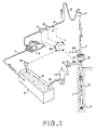
- Figure 1 shows the mud circuit of a well 1 during a formation fluid influx control operation.
- the bit 2 is attached to the end of a drill string 3.
- the mud circuit comprises a tank 4 containing drilling mud 5, a pump 6 sucking mud from the tank 4 through a pipe 7 and discharging it into the well 1, through a rigid pipe 8 and flexible hose 9 connected to the tubular drill string 3 via a swivel 17.
- the mud escapes from the drill string when it reaches the bit 2 and returns up the well through the annulus 10 between the drill string and the well wall.
- the drilling mud flows through a blow-out preventer 12 which is open.
- the mud flows into the mud tank 4 through a line 24 and through a vibratory screen not shown in the diagram to separate the cuttings from the mud.
- the valve 12 is closed. Having returned to the surface, the mud flows through a choke 13 and a degasser 14 which separates the gas from the liquid.
- the drilling mud then returns to the tank 4 through line 15.
- the mud inflow rate Q i is measured by means of a flow meter 16 and the mud density is measured by means of a sensor 21, both of these fitted in line 8.
- the injection pressure p i is measured by means of a sensor 18 on rigid line 8.
- the return pressure p r is measured by means of a sensor 19 fitted between the blow-out preventer 12 and the choke 13.
- the mud level n in the tank 4 is measured by means of a level sensor 20 fitted in the tank 4.
- the signals Q i , d m , p i , p r and n thus generated are applied to a processing device 22, where they are processed during the dynamic analysis of an influx as suggested within the scope of the present invention. It may, however, be noted that in order to exploit the present invention it is sufficient to measure p r or Q r on one hand and Q i or p i on the other.
- Figure 2 represents in simplified form the hydraulic circuit of a well when the operator is preparing to circulate the formation fluids that have entered the well. Immediately after detecting an influx, the pumps are shut down and the blow-out preventer 12 and choke 13 are closed. The well is thus isolated. The driller then measures the pressure p i in the pipes by means of the sensor 8 and the pressure p r in the annulus by means of sensor 19 between the wellhead and the control choke 13.
- the influx is a single-phase plug 40 of density d i . and height h encountered at the bottom of the well at depth L.
- the volume V i of this influx may be estimated by the increase in the level n of mud in the tank 4 associated with the entry of the formation fluid into the well.
- L be the total depth of the well, in other words the difference in elevation between the 19 and the bit 2.
- the influx is distributed through the mud over a distance h, as is shown in figure 2.
- the value of h is calculated as follows:
- the density d i of the influx is then calculated by the following formula: where d m is the density of the mud at the moment of detecting the influx, and f is the angle of deviation of the well from the vertical at the depth at which the influx is encountered. This calculation makes it possible to decide the type of fluid that has entered the well. However, as the estimate of V i obtained by observing the mud level in the tank 4 is marred by errors, it is difficult in practice to use this method to determine the nature of the influx.
- the annular pressure delay effect may be regarded as being largely due to the volume of mud in the annulus, and the pipe volume may be disregarded.
- the transients may then be described by the following equation: where V a is the total volume of the annulus, X a is the compressibility of the annulus and dp r is the variation in the return pressure p r occurring during time period dt.
- Q r is generally not measured directly in the system as described in figure 1. But the method described here could be applied all the more easily if such a measurement were made.
- p r k d Q r 2
- k d being a coefficient characterizing the choke when it has a given opening. If therefore the values of Q i and p r are recorded by the processing system 22 during a change of rate, it is possible to determine the values of the product of X a V a and the choke constant k d by means of the following differential equation obtained by combining equations (2) and (3):
- Equation (4) now contains only one unknown, X a V a , if the output rate Q r is measured.
- equation (4) may be written as follows: where the values of Q i and p r are measured as a function of time t.
- the delay in changes of pressure p r observed at the choke in relation to the variations in the pump rate is highly sensitive to the presence of gas in the annulus.
- the method therefore consists in circulating the mud slowly through choke 13, and simultaneously recording the pressure p r read by sensor 19 and the rate Q i read by sensor 16 during the transient period. These data are then interpreted and the values of X a V a and k d calculated.
- the volume V a of the annulus being known, this makes it possible to estimate a mean compressibility X a of the fluids contained in the annulus.
- the value obtained is high compared to a predetermined value, which may be the compressibility X m of the mud, if this value is known, or alternatively the value of X a previously determined by the same method but in the absence of gas (during a calibration operation, for instance), it may be concluded that the fluid arriving from the formation is a gas. Once the presence of gas has been confirmed, its volume may be estimated.
- a predetermined value which may be the compressibility X m of the mud, if this value is known, or alternatively the value of X a previously determined by the same method but in the absence of gas (during a calibration operation, for instance).
- Figure 3 illustrates the proposed method within the scope of the present invention.
- Data plotted in figure 3 were obtained from tests carried out under controlled conditions where a known quantity of gas was injected at the bottom of an experimental well.
- the pressure delay p r with a change of rate Q i may be noted on the recording in figure 3 made as a function of time t.
- This figure also shows variations in the output rate Q r and injection pressure p i . It will be noted that the values of Q r also change with some delay compared to the values of Q i or p i .
Landscapes
- Engineering & Computer Science (AREA)
- Geology (AREA)
- Life Sciences & Earth Sciences (AREA)
- Mining & Mineral Resources (AREA)
- Physics & Mathematics (AREA)
- Environmental & Geological Engineering (AREA)
- Fluid Mechanics (AREA)
- General Life Sciences & Earth Sciences (AREA)
- Geochemistry & Mineralogy (AREA)
- Geophysics (AREA)
- Mechanical Engineering (AREA)
- Earth Drilling (AREA)
- Excavating Of Shafts Or Tunnels (AREA)
- Investigating Or Analysing Materials By Optical Means (AREA)
Applications Claiming Priority (2)
| Application Number | Priority Date | Filing Date | Title |
|---|---|---|---|
| FR8711258 | 1987-08-07 | ||
| FR8711258A FR2619155B1 (fr) | 1987-08-07 | 1987-08-07 | Procede d'analyse dynamique des venues de fluides dans les puits d'hydrocarbures |
Publications (2)
| Publication Number | Publication Date |
|---|---|
| EP0302558A1 true EP0302558A1 (fr) | 1989-02-08 |
| EP0302558B1 EP0302558B1 (fr) | 1992-04-22 |
Family
ID=9354007
Family Applications (1)
| Application Number | Title | Priority Date | Filing Date |
|---|---|---|---|
| EP88201610A Expired - Lifetime EP0302558B1 (fr) | 1987-08-07 | 1988-07-26 | Procédé d'analyse des venues de fluides dans les puits d'hydrocarbures |
Country Status (6)
| Country | Link |
|---|---|
| US (1) | US5070949A (fr) |
| EP (1) | EP0302558B1 (fr) |
| CA (1) | CA1325278C (fr) |
| DE (1) | DE3870348D1 (fr) |
| FR (1) | FR2619155B1 (fr) |
| NO (1) | NO172907C (fr) |
Cited By (3)
| Publication number | Priority date | Publication date | Assignee | Title |
|---|---|---|---|---|
| GB2239279A (en) * | 1989-12-20 | 1991-06-26 | Forex Neptune Sa | Controlling a fluid influx during the drilling of a borehole. |
| EP0458391A1 (fr) * | 1990-05-23 | 1991-11-27 | Services Petroliers Schlumberger | RhéomÀ¨tre à tuyaux |
| US7044237B2 (en) | 2000-12-18 | 2006-05-16 | Impact Solutions Group Limited | Drilling system and method |
Families Citing this family (24)
| Publication number | Priority date | Publication date | Assignee | Title |
|---|---|---|---|---|
| US6101871A (en) * | 1995-02-28 | 2000-08-15 | Sandra K. Myers | In-ground vapor monitoring device and method |
| US5730233A (en) * | 1996-07-22 | 1998-03-24 | Alberta Industrial Technologies Ltd. | Method for detecting changes in rate of discharge of fluid from a wellbore |
| RU2132945C1 (ru) * | 1997-10-14 | 1999-07-10 | Предприятие "Астраханьгазпром" РАО "Газпром" | Способ исследования поглощающих пластов |
| CA2256258C (fr) * | 1998-12-16 | 2007-10-02 | Konstandinos S. Zamfes | Epreuve par ecouvillonnage servant a determiner la productivite relative de la formation |
| RU2165519C1 (ru) * | 1999-10-22 | 2001-04-20 | ООО "Уренгойгазпром" ОАО "Газпром" | Способ исследования скважин |
| US6374925B1 (en) | 2000-09-22 | 2002-04-23 | Varco Shaffer, Inc. | Well drilling method and system |
| US7026950B2 (en) * | 2003-03-12 | 2006-04-11 | Varco I/P, Inc. | Motor pulse controller |
| RU2244105C1 (ru) * | 2003-08-11 | 2005-01-10 | ООО "Уренгойгазпром" | Способ исследования скважин |
| BR122017010168B1 (pt) | 2005-10-20 | 2018-06-26 | Transocean Sedco Forex Ventures Ltd. | Método para controlar pressão e/ou densidade de um fluido de perfuração |
| US9435162B2 (en) | 2006-10-23 | 2016-09-06 | M-I L.L.C. | Method and apparatus for controlling bottom hole pressure in a subterranean formation during rig pump operation |
| EA014363B1 (ru) * | 2006-10-23 | 2010-10-29 | Эм-Ай Эл. Эл. Си. | Способ и устройство для регулирования забойного давления в подземном пласте во время работы бурового насоса |
| US7950472B2 (en) * | 2008-02-19 | 2011-05-31 | Baker Hughes Incorporated | Downhole local mud weight measurement near bit |
| US8307913B2 (en) * | 2008-05-01 | 2012-11-13 | Schlumberger Technology Corporation | Drilling system with drill string valves |
| GB0819340D0 (en) * | 2008-10-22 | 2008-11-26 | Managed Pressure Operations Ll | Drill pipe |
| GB0905633D0 (en) | 2009-04-01 | 2009-05-13 | Managed Pressure Operations Ll | Apparatus for and method of drilling a subterranean borehole |
| GB2469119B (en) | 2009-04-03 | 2013-07-03 | Managed Pressure Operations | Drill pipe connector |
| CN102575502B (zh) * | 2009-09-15 | 2015-07-08 | 控制压力营运私人有限公司 | 用于钻探地下钻孔的方法 |
| US8235143B2 (en) * | 2010-07-06 | 2012-08-07 | Simon Tseytlin | Methods and devices for determination of gas-kick parametrs and prevention of well explosion |
| US8684109B2 (en) | 2010-11-16 | 2014-04-01 | Managed Pressure Operations Pte Ltd | Drilling method for drilling a subterranean borehole |
| US9458696B2 (en) | 2010-12-24 | 2016-10-04 | Managed Pressure Operations Pte. Ltd. | Valve assembly |
| US8965703B2 (en) * | 2011-10-03 | 2015-02-24 | Schlumberger Technology Corporation | Applications based on fluid properties measured downhole |
| US9033048B2 (en) * | 2011-12-28 | 2015-05-19 | Hydril Usa Manufacturing Llc | Apparatuses and methods for determining wellbore influx condition using qualitative indications |
| US11802480B2 (en) * | 2014-04-15 | 2023-10-31 | Halliburton Energy Services, Inc. | Determination of downhole conditions using circulated non-formation gasses |
| RU2684924C1 (ru) * | 2018-05-17 | 2019-04-16 | Федеральное государственное бюджетное образовательное учреждение высшего образования "Кубанский государственный технологический университет" (ФГБОУ ВО "КубГТУ") | Способ исследования разреза скважины в процессе бурения |
Citations (4)
| Publication number | Priority date | Publication date | Assignee | Title |
|---|---|---|---|---|
| DE1815725A1 (de) * | 1967-12-21 | 1969-07-17 | Dresser Ind | Verfahren und Anordnung zu selbsttaetigen Steuern des Abtoetens von OEl- und Gasschaechten |
| AT292328B (de) * | 1968-10-04 | 1971-08-25 | Manfred Dr Ing Lorbach | Vorrichtung zur Ein- und Ausflußmengenmessung an Bohrlöchern oder Sonden |
| US3760891A (en) * | 1972-05-19 | 1973-09-25 | Offshore Co | Blowout and lost circulation detector |
| US4253530A (en) * | 1979-10-09 | 1981-03-03 | Dresser Industries, Inc. | Method and system for circulating a gas bubble from a well |
Family Cites Families (7)
| Publication number | Priority date | Publication date | Assignee | Title |
|---|---|---|---|---|
| US3968844A (en) * | 1974-09-19 | 1976-07-13 | Continental Oil Company | Determining the extent of entry of fluids into a borehole during drilling |
| US4733233A (en) * | 1983-06-23 | 1988-03-22 | Teleco Oilfield Services Inc. | Method and apparatus for borehole fluid influx detection |
| US4553429A (en) * | 1984-02-09 | 1985-11-19 | Exxon Production Research Co. | Method and apparatus for monitoring fluid flow between a borehole and the surrounding formations in the course of drilling operations |
| US4635735A (en) * | 1984-07-06 | 1987-01-13 | Schlumberger Technology Corporation | Method and apparatus for the continuous analysis of drilling mud |
| US4606415A (en) * | 1984-11-19 | 1986-08-19 | Texaco Inc. | Method and system for detecting and identifying abnormal drilling conditions |
| FR2619156B1 (fr) * | 1987-08-07 | 1989-12-22 | Forex Neptune Sa | Procede de controle des venues de fluides dans les puits d'hydrocarbures |
| US5006845A (en) * | 1989-06-13 | 1991-04-09 | Honeywell Inc. | Gas kick detector |
-
1987
- 1987-08-07 FR FR8711258A patent/FR2619155B1/fr not_active Expired
-
1988
- 1988-07-26 DE DE8888201610T patent/DE3870348D1/de not_active Expired - Lifetime
- 1988-07-26 EP EP88201610A patent/EP0302558B1/fr not_active Expired - Lifetime
- 1988-08-02 CA CA000573547A patent/CA1325278C/fr not_active Expired - Fee Related
- 1988-08-05 NO NO883505A patent/NO172907C/no unknown
-
1991
- 1991-05-10 US US07/701,352 patent/US5070949A/en not_active Expired - Fee Related
Patent Citations (4)
| Publication number | Priority date | Publication date | Assignee | Title |
|---|---|---|---|---|
| DE1815725A1 (de) * | 1967-12-21 | 1969-07-17 | Dresser Ind | Verfahren und Anordnung zu selbsttaetigen Steuern des Abtoetens von OEl- und Gasschaechten |
| AT292328B (de) * | 1968-10-04 | 1971-08-25 | Manfred Dr Ing Lorbach | Vorrichtung zur Ein- und Ausflußmengenmessung an Bohrlöchern oder Sonden |
| US3760891A (en) * | 1972-05-19 | 1973-09-25 | Offshore Co | Blowout and lost circulation detector |
| US4253530A (en) * | 1979-10-09 | 1981-03-03 | Dresser Industries, Inc. | Method and system for circulating a gas bubble from a well |
Cited By (8)
| Publication number | Priority date | Publication date | Assignee | Title |
|---|---|---|---|---|
| GB2239279A (en) * | 1989-12-20 | 1991-06-26 | Forex Neptune Sa | Controlling a fluid influx during the drilling of a borehole. |
| EP0436242A1 (fr) * | 1989-12-20 | 1991-07-10 | SERVICES PETROLIERS SCHLUMBERGER, (formerly Société de Prospection Electrique Schlumberger) | Procédé d'analyse et de contrôle d'une venue de fluide pendant le forage d'un puits |
| US5080182A (en) * | 1989-12-20 | 1992-01-14 | Schlumberger Technology Corporation | Method of analyzing and controlling a fluid influx during the drilling of a borehole |
| GB2239279B (en) * | 1989-12-20 | 1993-06-16 | Forex Neptune Sa | Method of analysing and controlling a fluid influx during the drilling of a borehole |
| EP0458391A1 (fr) * | 1990-05-23 | 1991-11-27 | Services Petroliers Schlumberger | RhéomÀ¨tre à tuyaux |
| US7044237B2 (en) | 2000-12-18 | 2006-05-16 | Impact Solutions Group Limited | Drilling system and method |
| US7278496B2 (en) | 2000-12-18 | 2007-10-09 | Christian Leuchtenberg | Drilling system and method |
| US7367411B2 (en) | 2000-12-18 | 2008-05-06 | Secure Drilling International, L.P. | Drilling system and method |
Also Published As
| Publication number | Publication date |
|---|---|
| NO883505D0 (no) | 1988-08-05 |
| FR2619155A1 (fr) | 1989-02-10 |
| EP0302558B1 (fr) | 1992-04-22 |
| CA1325278C (fr) | 1993-12-14 |
| NO883505L (no) | 1989-02-08 |
| NO172907B (no) | 1993-06-14 |
| FR2619155B1 (fr) | 1989-12-22 |
| DE3870348D1 (de) | 1992-05-27 |
| NO172907C (no) | 1993-09-22 |
| US5070949A (en) | 1991-12-10 |
Similar Documents
| Publication | Publication Date | Title |
|---|---|---|
| EP0302558B1 (fr) | Procédé d'analyse des venues de fluides dans les puits d'hydrocarbures | |
| CA1296707C (fr) | Methode de controle des afflux de fluide dans un puits de petrole | |
| US5080182A (en) | Method of analyzing and controlling a fluid influx during the drilling of a borehole | |
| US3955411A (en) | Method for measuring the vertical height and/or density of drilling fluid columns | |
| US10132129B2 (en) | Managed pressure drilling with rig heave compensation | |
| CA1057081A (fr) | Appareil et methode permettant de mesurer abord d'un navire le debit du fluide de forage circulant dans une colonne montante, du puits de forage au navire | |
| US5006845A (en) | Gas kick detector | |
| US6427785B2 (en) | Subsurface measurement apparatus, system, and process for improved well drilling, control, and production | |
| US3910110A (en) | Motion compensated blowout and loss circulation detection | |
| US4961343A (en) | Method for determining permeability in hydrocarbon wells | |
| US11643891B2 (en) | Drilling system and method using calibrated pressure losses | |
| US20040065440A1 (en) | Dual-gradient drilling using nitrogen injection | |
| CA2829378A1 (fr) | Procede de caracterisation de formations souterraines utilisant une reponse de pression de fluide pendant des operations de forage | |
| CA2047587A1 (fr) | Detection de liquide entrant ou sortant d'un trou de forage | |
| Maus et al. | Instrumentation requirements for kick detection in deep water | |
| EP4731867A1 (fr) | Système et procédé de forage utilisant une fenêtre de forage déterminée de manière dynamique | |
| US3750766A (en) | Controlling subsurface pressures while drilling with oil base muds | |
| US4485675A (en) | Pneumatic fluid densiometer | |
| US11643928B2 (en) | Siphon pump chimney for formation tester | |
| US3911740A (en) | Method of and apparatus for measuring properties of drilling mud in an underwater well | |
| BR112021012437B1 (pt) | Sistema, conjunto e método utilizáveis em um ambiente de furo de poço | |
| GB2084221A (en) | A method and apparatus for compensating well control instrumentation for the effects of vessel heave |
Legal Events
| Date | Code | Title | Description |
|---|---|---|---|
| PUAI | Public reference made under article 153(3) epc to a published international application that has entered the european phase |
Free format text: ORIGINAL CODE: 0009012 |
|
| AK | Designated contracting states |
Kind code of ref document: A1 Designated state(s): DE GB IT NL |
|
| 17P | Request for examination filed |
Effective date: 19890620 |
|
| 17Q | First examination report despatched |
Effective date: 19901024 |
|
| RAP1 | Party data changed (applicant data changed or rights of an application transferred) |
Owner name: SERVICES PETROLIERS SCHLUMBERGER |
|
| GRAA | (expected) grant |
Free format text: ORIGINAL CODE: 0009210 |
|
| ITF | It: translation for a ep patent filed | ||
| AK | Designated contracting states |
Kind code of ref document: B1 Designated state(s): DE GB IT NL |
|
| REF | Corresponds to: |
Ref document number: 3870348 Country of ref document: DE Date of ref document: 19920527 |
|
| PLBE | No opposition filed within time limit |
Free format text: ORIGINAL CODE: 0009261 |
|
| STAA | Information on the status of an ep patent application or granted ep patent |
Free format text: STATUS: NO OPPOSITION FILED WITHIN TIME LIMIT |
|
| 26N | No opposition filed | ||
| PGFP | Annual fee paid to national office [announced via postgrant information from national office to epo] |
Ref country code: GB Payment date: 19990611 Year of fee payment: 12 |
|
| PGFP | Annual fee paid to national office [announced via postgrant information from national office to epo] |
Ref country code: NL Payment date: 19990729 Year of fee payment: 12 |
|
| PGFP | Annual fee paid to national office [announced via postgrant information from national office to epo] |
Ref country code: DE Payment date: 19990922 Year of fee payment: 12 |
|
| PG25 | Lapsed in a contracting state [announced via postgrant information from national office to epo] |
Ref country code: GB Free format text: LAPSE BECAUSE OF NON-PAYMENT OF DUE FEES Effective date: 20000726 |
|
| PG25 | Lapsed in a contracting state [announced via postgrant information from national office to epo] |
Ref country code: NL Free format text: LAPSE BECAUSE OF NON-PAYMENT OF DUE FEES Effective date: 20010201 |
|
| GBPC | Gb: european patent ceased through non-payment of renewal fee |
Effective date: 20000726 |
|
| NLV4 | Nl: lapsed or anulled due to non-payment of the annual fee |
Effective date: 20010201 |
|
| PG25 | Lapsed in a contracting state [announced via postgrant information from national office to epo] |
Ref country code: DE Free format text: LAPSE BECAUSE OF NON-PAYMENT OF DUE FEES Effective date: 20010501 |
|
| PG25 | Lapsed in a contracting state [announced via postgrant information from national office to epo] |
Ref country code: IT Free format text: LAPSE BECAUSE OF NON-PAYMENT OF DUE FEES;WARNING: LAPSES OF ITALIAN PATENTS WITH EFFECTIVE DATE BEFORE 2007 MAY HAVE OCCURRED AT ANY TIME BEFORE 2007. THE CORRECT EFFECTIVE DATE MAY BE DIFFERENT FROM THE ONE RECORDED. Effective date: 20050726 |