EP0302708A2 - Dispositif et procédé de traitement d eau saturée d oxygène sous haute pression - Google Patents
Dispositif et procédé de traitement d eau saturée d oxygène sous haute pression Download PDFInfo
- Publication number
- EP0302708A2 EP0302708A2 EP88307147A EP88307147A EP0302708A2 EP 0302708 A2 EP0302708 A2 EP 0302708A2 EP 88307147 A EP88307147 A EP 88307147A EP 88307147 A EP88307147 A EP 88307147A EP 0302708 A2 EP0302708 A2 EP 0302708A2
- Authority
- EP
- European Patent Office
- Prior art keywords
- oxygen
- high pressure
- improved high
- treatment apparatus
- tank
- Prior art date
- Legal status (The legal status is an assumption and is not a legal conclusion. Google has not performed a legal analysis and makes no representation as to the accuracy of the status listed.)
- Granted
Links
- XLYOFNOQVPJJNP-UHFFFAOYSA-N water Substances O XLYOFNOQVPJJNP-UHFFFAOYSA-N 0.000 title claims abstract description 229
- 238000011282 treatment Methods 0.000 title claims abstract description 160
- 238000000034 method Methods 0.000 title description 3
- 230000008569 process Effects 0.000 title description 2
- QVGXLLKOCUKJST-UHFFFAOYSA-N atomic oxygen Chemical compound [O] QVGXLLKOCUKJST-UHFFFAOYSA-N 0.000 claims abstract description 129
- 239000001301 oxygen Substances 0.000 claims abstract description 129
- 229910052760 oxygen Inorganic materials 0.000 claims abstract description 129
- 229920006395 saturated elastomer Polymers 0.000 claims abstract description 90
- 239000007789 gas Substances 0.000 claims abstract description 81
- 238000002347 injection Methods 0.000 claims abstract description 53
- 239000007924 injection Substances 0.000 claims abstract description 53
- 239000002351 wastewater Substances 0.000 claims abstract description 27
- 239000000243 solution Substances 0.000 claims abstract description 12
- 239000002245 particle Substances 0.000 claims abstract description 11
- 238000000926 separation method Methods 0.000 claims abstract description 11
- 150000002926 oxygen Chemical class 0.000 claims abstract description 8
- 230000000153 supplemental effect Effects 0.000 claims abstract description 7
- 239000007788 liquid Substances 0.000 claims description 85
- 238000002156 mixing Methods 0.000 claims description 46
- 239000000203 mixture Substances 0.000 claims description 39
- 230000008602 contraction Effects 0.000 claims description 15
- 239000002699 waste material Substances 0.000 claims description 10
- 239000010865 sewage Substances 0.000 claims description 6
- 239000010802 sludge Substances 0.000 claims description 6
- 230000001590 oxidative effect Effects 0.000 claims description 5
- 229940090044 injection Drugs 0.000 claims 18
- 239000000463 material Substances 0.000 abstract description 9
- 230000006870 function Effects 0.000 abstract description 6
- 238000000746 purification Methods 0.000 abstract 1
- 239000002910 solid waste Substances 0.000 abstract 1
- 239000000356 contaminant Substances 0.000 description 8
- 239000007787 solid Substances 0.000 description 6
- IJGRMHOSHXDMSA-UHFFFAOYSA-N Atomic nitrogen Chemical compound N#N IJGRMHOSHXDMSA-UHFFFAOYSA-N 0.000 description 4
- 230000005465 channeling Effects 0.000 description 4
- 208000036366 Sensation of pressure Diseases 0.000 description 3
- 238000004090 dissolution Methods 0.000 description 3
- 239000010842 industrial wastewater Substances 0.000 description 3
- 239000002184 metal Substances 0.000 description 3
- CURLTUGMZLYLDI-UHFFFAOYSA-N Carbon dioxide Chemical compound O=C=O CURLTUGMZLYLDI-UHFFFAOYSA-N 0.000 description 2
- 238000013459 approach Methods 0.000 description 2
- 230000008901 benefit Effects 0.000 description 2
- 229910052757 nitrogen Inorganic materials 0.000 description 2
- 239000011368 organic material Substances 0.000 description 2
- 230000009467 reduction Effects 0.000 description 2
- 229910000831 Steel Inorganic materials 0.000 description 1
- 230000015572 biosynthetic process Effects 0.000 description 1
- 238000009835 boiling Methods 0.000 description 1
- 229910002092 carbon dioxide Inorganic materials 0.000 description 1
- 239000001569 carbon dioxide Substances 0.000 description 1
- 230000015556 catabolic process Effects 0.000 description 1
- 241001233037 catfish Species 0.000 description 1
- 238000005352 clarification Methods 0.000 description 1
- 238000010276 construction Methods 0.000 description 1
- 238000011109 contamination Methods 0.000 description 1
- 238000006731 degradation reaction Methods 0.000 description 1
- 230000003635 deoxygenating effect Effects 0.000 description 1
- 238000009792 diffusion process Methods 0.000 description 1
- 230000000694 effects Effects 0.000 description 1
- 238000007710 freezing Methods 0.000 description 1
- 230000008014 freezing Effects 0.000 description 1
- 239000008246 gaseous mixture Substances 0.000 description 1
- 230000005484 gravity Effects 0.000 description 1
- JEGUKCSWCFPDGT-UHFFFAOYSA-N h2o hydrate Chemical compound O.O JEGUKCSWCFPDGT-UHFFFAOYSA-N 0.000 description 1
- 239000010800 human waste Substances 0.000 description 1
- 230000007246 mechanism Effects 0.000 description 1
- 238000005065 mining Methods 0.000 description 1
- 238000012986 modification Methods 0.000 description 1
- 230000004048 modification Effects 0.000 description 1
- 230000003647 oxidation Effects 0.000 description 1
- 238000007254 oxidation reaction Methods 0.000 description 1
- 239000011236 particulate material Substances 0.000 description 1
- 238000009372 pisciculture Methods 0.000 description 1
- 230000003716 rejuvenation Effects 0.000 description 1
- 239000011343 solid material Substances 0.000 description 1
- 229910001220 stainless steel Inorganic materials 0.000 description 1
- 239000010935 stainless steel Substances 0.000 description 1
- 239000010959 steel Substances 0.000 description 1
- 239000000126 substance Substances 0.000 description 1
- 230000002459 sustained effect Effects 0.000 description 1
- 238000004065 wastewater treatment Methods 0.000 description 1
Images


Classifications
-
- C—CHEMISTRY; METALLURGY
- C02—TREATMENT OF WATER, WASTE WATER, SEWAGE, OR SLUDGE
- C02F—TREATMENT OF WATER, WASTE WATER, SEWAGE, OR SLUDGE
- C02F3/00—Biological treatment of water, waste water, or sewage
- C02F3/02—Aerobic processes
- C02F3/12—Activated sludge processes
- C02F3/1278—Provisions for mixing or aeration of the mixed liquor
- C02F3/1289—Aeration by saturation under super-atmospheric pressure
-
- B—PERFORMING OPERATIONS; TRANSPORTING
- B01—PHYSICAL OR CHEMICAL PROCESSES OR APPARATUS IN GENERAL
- B01F—MIXING, e.g. DISSOLVING, EMULSIFYING OR DISPERSING
- B01F23/00—Mixing according to the phases to be mixed, e.g. dispersing or emulsifying
- B01F23/20—Mixing gases with liquids
- B01F23/23—Mixing gases with liquids by introducing gases into liquid media, e.g. for producing aerated liquids
- B01F23/232—Mixing gases with liquids by introducing gases into liquid media, e.g. for producing aerated liquids using flow-mixing means for introducing the gases, e.g. baffles
-
- B—PERFORMING OPERATIONS; TRANSPORTING
- B01—PHYSICAL OR CHEMICAL PROCESSES OR APPARATUS IN GENERAL
- B01F—MIXING, e.g. DISSOLVING, EMULSIFYING OR DISPERSING
- B01F23/00—Mixing according to the phases to be mixed, e.g. dispersing or emulsifying
- B01F23/20—Mixing gases with liquids
- B01F23/23—Mixing gases with liquids by introducing gases into liquid media, e.g. for producing aerated liquids
- B01F23/2366—Parts; Accessories
- B01F23/2368—Mixing receptacles, e.g. tanks, vessels or reactors, being completely closed, e.g. hermetically closed
-
- B—PERFORMING OPERATIONS; TRANSPORTING
- B01—PHYSICAL OR CHEMICAL PROCESSES OR APPARATUS IN GENERAL
- B01F—MIXING, e.g. DISSOLVING, EMULSIFYING OR DISPERSING
- B01F23/00—Mixing according to the phases to be mixed, e.g. dispersing or emulsifying
- B01F23/40—Mixing liquids with liquids; Emulsifying
- B01F23/45—Mixing liquids with liquids; Emulsifying using flow mixing
- B01F23/454—Mixing liquids with liquids; Emulsifying using flow mixing by injecting a mixture of liquid and gas
-
- B—PERFORMING OPERATIONS; TRANSPORTING
- B01—PHYSICAL OR CHEMICAL PROCESSES OR APPARATUS IN GENERAL
- B01F—MIXING, e.g. DISSOLVING, EMULSIFYING OR DISPERSING
- B01F25/00—Flow mixers; Mixers for falling materials, e.g. solid particles
- B01F25/20—Jet mixers, i.e. mixers using high-speed fluid streams
- B01F25/21—Jet mixers, i.e. mixers using high-speed fluid streams with submerged injectors, e.g. nozzles, for injecting high-pressure jets into a large volume or into mixing chambers
-
- B—PERFORMING OPERATIONS; TRANSPORTING
- B01—PHYSICAL OR CHEMICAL PROCESSES OR APPARATUS IN GENERAL
- B01F—MIXING, e.g. DISSOLVING, EMULSIFYING OR DISPERSING
- B01F25/00—Flow mixers; Mixers for falling materials, e.g. solid particles
- B01F25/30—Injector mixers
- B01F25/31—Injector mixers in conduits or tubes through which the main component flows
- B01F25/312—Injector mixers in conduits or tubes through which the main component flows with Venturi elements; Details thereof
-
- B—PERFORMING OPERATIONS; TRANSPORTING
- B01—PHYSICAL OR CHEMICAL PROCESSES OR APPARATUS IN GENERAL
- B01F—MIXING, e.g. DISSOLVING, EMULSIFYING OR DISPERSING
- B01F25/00—Flow mixers; Mixers for falling materials, e.g. solid particles
- B01F25/30—Injector mixers
- B01F25/31—Injector mixers in conduits or tubes through which the main component flows
- B01F25/312—Injector mixers in conduits or tubes through which the main component flows with Venturi elements; Details thereof
- B01F25/3124—Injector mixers in conduits or tubes through which the main component flows with Venturi elements; Details thereof characterised by the place of introduction of the main flow
- B01F25/31242—Injector mixers in conduits or tubes through which the main component flows with Venturi elements; Details thereof characterised by the place of introduction of the main flow the main flow being injected in the central area of the venturi, creating an aspiration in the circumferential part of the conduit
-
- B—PERFORMING OPERATIONS; TRANSPORTING
- B01—PHYSICAL OR CHEMICAL PROCESSES OR APPARATUS IN GENERAL
- B01F—MIXING, e.g. DISSOLVING, EMULSIFYING OR DISPERSING
- B01F25/00—Flow mixers; Mixers for falling materials, e.g. solid particles
- B01F25/50—Circulation mixers, e.g. wherein at least part of the mixture is discharged from and reintroduced into a receptacle
- B01F25/53—Circulation mixers, e.g. wherein at least part of the mixture is discharged from and reintroduced into a receptacle in which the mixture is discharged from and reintroduced into a receptacle through a recirculation tube, into which an additional component is introduced
-
- C—CHEMISTRY; METALLURGY
- C02—TREATMENT OF WATER, WASTE WATER, SEWAGE, OR SLUDGE
- C02F—TREATMENT OF WATER, WASTE WATER, SEWAGE, OR SLUDGE
- C02F1/00—Treatment of water, waste water, or sewage
- C02F1/72—Treatment of water, waste water, or sewage by oxidation
-
- C—CHEMISTRY; METALLURGY
- C02—TREATMENT OF WATER, WASTE WATER, SEWAGE, OR SLUDGE
- C02F—TREATMENT OF WATER, WASTE WATER, SEWAGE, OR SLUDGE
- C02F3/00—Biological treatment of water, waste water, or sewage
- C02F3/02—Aerobic processes
- C02F3/12—Activated sludge processes
- C02F3/1278—Provisions for mixing or aeration of the mixed liquor
- C02F3/1294—"Venturi" aeration means
-
- C—CHEMISTRY; METALLURGY
- C02—TREATMENT OF WATER, WASTE WATER, SEWAGE, OR SLUDGE
- C02F—TREATMENT OF WATER, WASTE WATER, SEWAGE, OR SLUDGE
- C02F3/00—Biological treatment of water, waste water, or sewage
- C02F3/02—Aerobic processes
- C02F3/12—Activated sludge processes
- C02F3/26—Activated sludge processes using pure oxygen or oxygen-rich gas
-
- Y—GENERAL TAGGING OF NEW TECHNOLOGICAL DEVELOPMENTS; GENERAL TAGGING OF CROSS-SECTIONAL TECHNOLOGIES SPANNING OVER SEVERAL SECTIONS OF THE IPC; TECHNICAL SUBJECTS COVERED BY FORMER USPC CROSS-REFERENCE ART COLLECTIONS [XRACs] AND DIGESTS
- Y02—TECHNOLOGIES OR APPLICATIONS FOR MITIGATION OR ADAPTATION AGAINST CLIMATE CHANGE
- Y02W—CLIMATE CHANGE MITIGATION TECHNOLOGIES RELATED TO WASTEWATER TREATMENT OR WASTE MANAGEMENT
- Y02W10/00—Technologies for wastewater treatment
- Y02W10/10—Biological treatment of water, waste water, or sewage
-
- Y—GENERAL TAGGING OF NEW TECHNOLOGICAL DEVELOPMENTS; GENERAL TAGGING OF CROSS-SECTIONAL TECHNOLOGIES SPANNING OVER SEVERAL SECTIONS OF THE IPC; TECHNICAL SUBJECTS COVERED BY FORMER USPC CROSS-REFERENCE ART COLLECTIONS [XRACs] AND DIGESTS
- Y10—TECHNICAL SUBJECTS COVERED BY FORMER USPC
- Y10S—TECHNICAL SUBJECTS COVERED BY FORMER USPC CROSS-REFERENCE ART COLLECTIONS [XRACs] AND DIGESTS
- Y10S261/00—Gas and liquid contact apparatus
- Y10S261/75—Flowing liquid aspirates gas
Definitions
- the present invention relates generally to water treatment apparatus, and more particularly to an improved high pressure oxygen-saturated water treatment apparatus for providing super-saturated oxygen treatment to waste water.
- Such apparatus may find a wide variety of usages in the treatment of waste water containing human waste, rejuvenation of swamps, cleansing water for cat fish farming, or for agriculture, and/or during mining operations and for a wide variety of usages where it is desirable to purify waste water, or to provide oxidizing and entraining bubbles of oxygen about solid particulate material.
- Sewage treatment plants are concerned for the most part with effecting substantial reductions in biochemical oxygen demand and suspended solids levels of raw sewage and industrial waste water before the treatment plant effluent is discharged to a river or the like. Pollution control regulations in effect throughout the United States set limits on permissible levels of biochemical oxygen demand and suspended solids that will be tolerated. Sewage treatment personnel, and industrial waste water treatment firms, are continuously alert for more efficient and economical ways of reducing the concentration and quantity of biochemical oxygen demand containing materials in waste water.
- One area which has previously been investigated to some extent involves creation of oxygen-enriched clean water, followed by contact of the oxygen-enriched water with waste water to be treated.
- the excess oxygen in the enriched water brings about rapid degradation of the wastes, and thereby cleanses the waste water to acceptable contaminant levels.
- the present invention is concerned with provision of an oxygen-enriched water stream useful for contacting and for the resultant cleansing of waste water.
- the waste water to be treated contains suspended solids along with dissolved inorganic and organic contaminants. These contaminants represent a high demand for any available oxygen.
- the waste water has relatively high biochemical oxygen demand and relatively high chemical oxygen demand, which are parameters of the polluting characteristics of the waste water.
- the contaminants of the waste water tend to undergo oxidation.
- the oxygen-enriched stream tends to satisfy the oxygen demand of the waste water.
- the inorganic contaminants oxidize to less soluble oxides, while the organic components are converted to carbonaceous residues and carbon dioxide.
- the insolublized components then generally rise to the surface of the waste water where they may be removed by any of several techniques, such as surface skimming, for example, which are known to those of ordinary skill in the art.
- the gas-liquid combination system of the present invention which generates the oxygen-enriched cleansing water, utilizes in a novel manner several well-known physical principles.
- the principal mechanisms by which the oxygen-enrichment is created are believed to be through diffusion and dissolution of the oxygen component of air in water. In the process of diffusing air in water, the system relies on both Henry's Law and Dalton's Law of Partial Pressures.
- the dissolved gas tends to remain in solution so long as the equilibrium pressure remains undisturbed.
- the amount of oxygen dissolved in water in a sealed vessel at, for example 100 P.S.I. will tend to stay in the water until the diffused solution is discharged from the vessel into another vessel under lower pressure or into the atmosphere.
- some of the dissolved gas escapes and forms small microscopic-size bubbles (the gaseous form of lowest energy is spherical, hence the formation of bubbles).
- These bubbles behave in a way predictable by the Nucleus Theory, according to which a gas coming out of solution from a liquid tends to form bubbles of finite nuclei.
- This concept is used to advantage in utilization of the product of the present invention, as such bubbles tend to collect about small particles of solid material, in this case the suspended waste solids, to form larger particles of lesser specific gravity which tend to rise to the surface, resulting in clarification of the liquid. Such high air-entrained waste can then readily be skimmed off for disposal.
- the improved high pressure oxygen-saturated water treatment apparatus of the present invention is directed to apparatus for providing super-saturated oxygen treatment to water for purifying waste water.
- the apparatus includes a pressurized treatment tank having a substantial longitudinal dimension of preferably cylindrical shape.
- Such tank has therewithin a chamber separation means, preferably in the form of a transversely disposed metal plate, forming two interconnected chambers in the tank.
- An input conduit for flowing waste water into the first chamber of the tank is provided.
- An oxygen input means is also disposed on the tank for providing and for maintaining oxygen-containing gas under substantial pressure within the tank.
- Oxygen output means are also disposed on the tank for receiving the oxygen-containing gas from the tank to form a pressurized oxygen-containing stream.
- a venturi is disposed on the tank for receiving and combining the pressurized oxygen-containing stream with recirculation water from the tank to form a combined injection stream of pressurized water which is super-saturated with oxygen and which is then injected into the treatment water contained within the tank.
- the result is to substantially oxidize any oxidizable material contained within the tank.
- the treated water is then removed by suitable means from the tank from the second chamber thereof.
- Such pressurized tank may be pressurized preferively to at least approximately 80 to 120 P.S.I., or above, and to contain therewithin oxygen-containing gas pressurized to that pressure.
- the venturi means in some preferred embodiments of the improved high pressure oxygen-saturated water treatment apparatus of the present invention includes a venturi housing, and with a gas-liquid mixing container disposed therewithin.
- gas-liquid mixing container in preferred embodiments may include longitudinal slits on the walls thereof.
- Such walls of the gas-liquid mixing chamber define an exteriorly disposed gas chamber and an interiorly disposed liquid chamber for receipt of treatment water thereinto.
- Such slots function to define gas input openings in the walls of the mixing container for flowing of the oxygen-containing gas thereinto under substantial pressure to mix with the water contained therewithin.
- Gas input means are disposed on the venturi housing for providing oxygen-containing gas to the gas chamber.
- Liquid input means are provided for providing water to and to flow through the liquid chamber.
- a mixture injection chamber connected to the venturi housing and for channeling the mixed oxygen-containing pressurized gas and water injection mixture in a direction generally longitudinal of such gas-liquid mixing chamber is further provided.
- the improved high pressure oxygen-saturated water treatment apparatus of the present invention functions to provide super-saturated oxygen treatment water, such as various forms of waste water, also known as treatment water, and in some preferred embodiments containing organic materials.
- Such apparatus includes a pressurized treatment tank having a substantial longitudinal dimension.
- a chamber separation means is disposed within the pressurized treatment tank for defining two inter-connected chambers within the tank.
- the chamber separation means preferably in the form of a transversely disposed metal plate, includes an aperture therein for permitting the flow of water therethrough from a first chamber to a second chamber.
- Treatment water input means preferably in the form of a conduit, are disposed on the tank for input of treatment water into the first chamber of the pressurized treatment tank.
- Recirculation water means are also disposed on the tank for receiving a stream of recirculation water from the tank, and preferably from the bottom portion thereof.
- Oxygen input means are disposed on the tank for providing oxygen-containing gas into the tank and for maintaining such oxygen-containing gas under substantial pressure within the tank.
- Oxygen output means are disposed on the tank for receiving the pressurized oxygen-containing gas from the tank to form a pressurized oxygen-containing stream.
- a venturi is disposed on the tank for receiving and combining the pressurized oxygen-containing stream with the recirculation water stream, and under substantial pressure, to form a combined injection stream of pressurized water which is super-saturated with oxygen, and which combined injection stream is injected into the treatment water contained within the tank for substantially oxidizing any oxidizable material contained within such treatment water.
- Such combined stream is injected in preferred embodiments into the first chamber of the tank.
- treated water output means are also disposed on the tank for output of treated water, which contains substantially reduced levels of oxidizable contaminants, such treated water output preferably disposed for removal of treated water from the second chamber of the tank.
- the oxygen output means in preferred embodiments is disposed at the top of the tank.
- the pressurized treatment tank is substantially cylindrical in preferred embodiments in external configuration, and may be pressurized to at least approximately 80 to 120 P.S.I.
- the first chamber of the tank is disposed below the second chamber.
- aperture means are disposed centrally with respect to the longitudinal axis of the tank. Such aperture means may have a standpipe disposed on and extending upwardly therefrom.
- the oxygen-containing gas may comprise air, or may comprise oxygen, or other gaseous mixtures containing substantial portions of oxygen.
- oxygen-containing gas is preferably pressurized to at least approximate 80 to 120 PS.I.
- the treated water output means in preferred embodiments is disposed below the level of water contained within the second chamber of the tank.
- Such oxidizable matter contained within the waste water may be of the type having substantial biochemical oxygen demand.
- Such waste water may contain human sewage.
- the recirculation water means may include a recirculation water pump. Such recirculation water means is preferably disposed on the first chamber of the tank for withdrawing a stream of recirculation water therefrom.
- a plurality of such venturi means is disposed about the periphery of the tank, and preferably in equally disposed array. In some preferivelyred embodiments, four such venturi means may disposed about the periphery of the tank 90° apart.
- Water level control means are provided for such tank in preferred embodiments. Such water level control means function to maintain a head space within the tank of oxygen-containing gas. Such head space of preferred embodiments may comprise approximately one-third of the longitudinal dimension of the tank.
- the pressurized oxygen-containing stream from the venturi means in preferred embodiments may include approximately at least approximately 3,000 P.P.M. of dissolved oxygen or greater amounts in other preferred embodiments.
- biochemical oxygen demand in preferred embodiments of the improved high pressure oxygen-saturated water treatment apparatus of the present invention may be reduced by at least approximately 90 per cent.
- the venturi means in preferred embodiments further includes a venturi pressure pump for supplying supplemental pressure to the output therefrom.
- the pressure inside the tank in preferred embodiments is preferably a lower pressure than the pressure of the pressurized oxygen-containing stream within the venturi means, and thus dissolved oxygen will come out of solution within the tank.
- dissolved oxygen when such dissolved oxygen comes out of solution, it does so preferentially about any suspended sludge particles within the treatment water, thus entraining the suspended sludge particles and providing supplemental floatation thereto.
- the standpipe in such preferred embodiments is disposed about the aperture in the chamber separation means and extends to a longitudinal dimension which may be approximately one third of the longitudinal dimension of the tank.
- the venturi means are disposed for injecting the pressurized water which is super-saturated with oxygen at a level of approximately one-third of the distance from the bottom of the tank to the top thereof.
- the treated water output means are disposed at approximately the mid-point of the longitudinal dimension of the tank. Such standpipe preferably extends slightly about the horizontal center of the tank.
- venturi means is preferably disposed on the discharge side of the venturi pressurized pump.
- gas-liquid mixing container defines an exteriorly disposed gas chamber and in interiorly disposed liquid chamber for receipt of water thereinto.
- gas-liquid mixing container further defines gas openings in the walls of said mixing container for flowing of the oxygen-containing gas therethrough under substantial pressure to mix with the water within and flowing through the liquid chamber.
- Gas input means are disposed on the venturi housing for providing oxygen-containing gas to the gas chamber.
- Liquid input means are provided for providing water to and to flow through the liquid chamber.
- a mixture injection chamber is connected to the venturi housing and is provided for channeling the mixed oxygen-containing pressurized gas and water injection mixture in a direction generally longitudinal of the gas-liquid mixing chamber.
- substantially smoothly contoured contraction means disposed within the venturi housing and for conveying the water in a longitudinal path into and through the gas-liquid mixing container and for increasing the velocity of the water exiting from the contoured contraction means.
- Such smoothly contoured contraction means preferably comprises a substantially frusto-conical initial chamber and passing into a connected substantially cylindrical second chamber of reduced diameter.
- the smoothly contoured contraction means is preferably defined by a fitting for disposition within the mouth of the gas-liquid mixing chamber. At least a portion of the exterior shape of such fitting is frusto-conical in shape. Also, such frusto-conical exterior shape of the fitting comprising the smoothly contoured contraction means is disposed within the gas-liquid chamber.
- the venturi means may further comprise a gas-liquid mixture reception means for receiving the highly oxygenated water from the gas-liquid chamber.
- gas-liquid reception means is disposed within the gas-liquid mixing container and downstream of the gas openings therein.
- gas-liquid mixture reception means further includes, in preferred embodiments, a substantially frusto-conical pickup mouth channeling into a connected substantially cylindrical output mouth means for directing the stream of oxygen-enriched water into the mixture injection chamber.
- Such substantially cylindrical output mouth means in preferred embodiments may be of reduced diameter as compared with the larger diameter of the frusto-conical pickup mouth for increasing the velocity thereof preparatory to injection of the substantially oxygen-enriched stream of water into the mixture injection chamber.
- the interior diameter of the output means of the gas-liquid reception means is of larger interior diameter than that of the most adjacent portion of the liquid input means.
- the venturi housing may be substantially cylindrical in shape.
- the gas-liquid mixing container may be substantially cylindrical in shape.
- Such gas-liquid mixing chamber in preferred embodiments preferivelyably includes a plurality of slots in the walls thereof for passage of oxygen-containing gas therethrough.
- Such slots in preferred embodiments are elongated in shape and are disposed substantially parallel to the longitudinal axis of the gas-liquid mixing chamber. In such preferred embodiments such slots are disposed in substantially equally spaced array about the circumference of the gas-liquid chamber.
- the mixture injection chamber is also cylindrical in shape.
- the transverse cross-sectional area of the mixture injection chamber is preferably less than that of the gas-liquid mixing container.
- the length of the mixture injection chamber is in preferred embodiments substantially greater than the length of the venturi housing.
- the mixture injection chamber further comprises relief openings in the walls thereof near the distal end thereof, and which distal end includes a discharge portion thereof.
- the improved high pressure oxygen-saturated water treatment apparatus generally 10 of the present invention functions to provide super-saturated oxygen treatment water, such as various forms of waste water, and in some preferred embodiments containing organic materials.
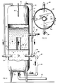
- Such apparatus includes a pressurized treatment tank 12 having a substantial longitudinal dimension as shown in Figs. 1 and 2. Tank 12 may be supported by legs 13 of suitable dimensions, materials and strength.
- a chamber separation plate 14 is disposed within pressurized treatment tank 12 for defining two inter-connected chambers 16,18 within tank 12.
- Chamber separation plate 14 preferably in the form of a transversely disposed metal plate, inlcudes an aperture 20 therein for permitting the flow of water therethrough from first chamber 16 to second chamber 18 (See Arrow A).
- a treatment water input conduit 222 is disposed on tank 12 for input of treatment water into first chamber 16 of the pressurized treatment tank 12 at the bottom 24 thereof (See Arrow B).
- Recirculation water conduit 26 is also disposed on tank 12 also at bottom 24 for receiving a stream of recirculation water from tank 12 (See Arrow C), and preferably from the bottom 24, as shown in Figs. 1 and 2.
- An oxygen input conduit 28 is also connected to tank 12 for providing oxygen-containing gas into the tank and for maintaining such oxygen-containing gas under substantial pressure within tank 12.
- Such oxygen input conduit 28 may be connected to a compressor and to feed into treatment water input conduit 22, or in alternative embodiments may feed directly into tank 12.
- An oxygen output conduit 30 is disposed on tank 12 and at top portion 32 thereof for receiving the pressurized oxygen-containing gas from tank 12 to form a pressurized oxygen-containing stream contained within oxygen output conduit 30 (See Arrow D).
- a venturi generally 34 is disposed on tank 12 for receiving and combining the pressurized oxygen-containing stream (See Arrow D) with the recirculation water stream (See Arrow C), and under substantial pressure, to form a combined injection stream 36 (See Arrow E of Fig. 4) of pressurized water which is super-saturated with oxygen, and which combined injection stream is injected into the treatment water contained within tank 12 for substantially oxidizing any oxidizable material contained within such treatment water.
- Such combined stream 36 is injected in preferred embodiments into the first chamber 16 of tank 12.
- a treated water output conduit 38 is also disposed on tank 12 for output of treated water (See Arrow F), which contains substantially reduced levels of oxidizable contaminants, such treated water output preferably from second chamber 18 of tank 12.
- Pressurized treatment tank 12 is substantially cylindrical in preferred embodiments in external configuration, and may be pressurized to at least approximately 80 to 120 P.S.I.
- First chamber 16 of tank 12 is disposed below second chamber 18 as shown in Fig. 1.
- Aperture 20 is disposed centrally with respect to the longitudinal axis of tank 12. Such aperture 20 may have a standpipe 40 disposed on and extending upwardly therefrom, as shown in Fig. 1.
- treated water output conduit 38 is disposed below the level of water contained within second chamber 18 of tank 12.
- recirculation water conduit 26 may include a recirculation water pump 42.
- Such recirculation water conduit 26 is preferably disposed on first chamber 16 of tank 12 for withdrawing a stream of recirculation water therefrom (See Arrow C).
- venturis 34 are disposed about periphery 44 of tank 12, and preferivelyably in equally disposed array. In some preferred embodiments, as shown in Fig. 2 such venturis 34 may be disposed about periphery 44 of tank 12 and 90° apart.
- Water level control means such as for example in the form of a McDonald valve, are provided for such tank 12.
- Such water level control valve (not shown) func tions to maintain a head space 46 within tank 12 of the oxygen-containing gas.
- head space 46 of preferred embodiments may comprise approximately one-third of the longitudinal dimension of tank 12, as shown in Fig. 1.
- the pressurized oxygen-containing stream from the venturi means in preferred embodiments may include at least approximately 3,000 to 4,000 P.P.M. of dissolved oxygen, or greater amounts in other preferred embodiments.
- biochemical oxygen demand in preferred embodiments of the improved high pressure oxygen-saturated water treatment apparatus 10 of the present invention are reduced by at least approximately 90 per cent.
- venturi 34 further includes a venturi pressure pump 48 for supplying supplemental pressure to the output therefrom.
- the pressure inside tank 12 in preferred embodiments is preferably a lower pressure than the pressure of the pressurized oxygen-containing stream within venturi 34, and thus dissolved oxygen will come out of solution within tank 12 upon injection of such combined injection stream 36 into tank 12.
- dissolved oxygen comes out of solution, it does so preferentially about any suspended sludge particles within the treatment water, thus entraining the suspended sludge particles and providing supplemental floatation thereto.
- Standpipe 40 in such preferred embodiments is disposed about aperture 20 in chamber separation plate 14 extends to a longitudinal dimension which may be approximately one-third of the longitudinal dimension of tank 12.
- Venturis 34 are disposed for injecting the pressurized water which is super-saturated with oxygen at a level of approximately one-third of the distance from bottom 24 of tank 12 to top 46 thereof.
- the treated water output conduits 38 are disposed at approximately the mid-point of the longitudinal dimension of tank 12.
- Such standpipe 40 preferably extends slightly about the horizontal center of tank 12.
- each such venturi 34 is preferably disposed on the discharge side 50 of venturi pressurized pump 48.
- one preferred embodiment of a venturi 34 for use in connection with improved high pressure oxygen-saturated water treatment apparatus 10 of the present invention includes a venturi housing 52 containing a gas-liquid mixing container 54 disposed therewithin.
- gas-liquid mixing container 54 defines an exteriorly disposed gas chamber 56 and an interiorly disposed liquid chamber 58 for receipt of water thereinto.
- gas-liquid mixing container 54 further defines gas openings 59 in walls 60 of said mixing container 54 for flowing of the oxygen-containing gas therethrough under substantial pressure to mix with the water within and flowing through liquid chamber 58.
- the pressure of gas within gas chamber 56 must be sufficiently great to prevent backup of treatment water therein from liquid chamber 58.
- a gas input opening 62 is disposed on venturi housing 52 for providing oxygen-containing gas to gas chamber 56.
- a liquid input opening is provided for providing water to and to flow through liquid chamber 58.
- a mixture injection chamber 64 is connected to venturi housing 52 and is provided for channelling the mixed oxygen- containing pressurized gas and water injection mixture in a direction generally longitudinally of the gas-liquid mixing container 54, as shown generally at Arrow E.
- a substantially smoothly contoured contraction 66 disposed within venturi housing 52 and for conveying the water in a longitudinal path into and through gas-liquid mixing container 54 and for increasing the velocity of the water exiting from the contoured contraction 66.
- Such smoothly contoured contraction 66 preferably comprises a substantially frusto-conical initial chamber 68 and passing into a connected substantially cylindrical second chamber 70 of reduced diameter.
- Smoothly contoured contraction 66 is preferably defined by a fitting generally 72 for disposition within mouth 74 of gas-liquid mixing container 54. At least a portion 76 of the exterior shape of fitting 72 is frusto-conical in shape.
- Such frusto-conical exterior shape 76 of fitting 72 comprising smoothly contoured contraction 66 is disposed within the gas-liquid mixing container 54.
- Venturi 34 may further comprise a gas-liquid mixture reception element generally 78 for receiving the highly oxygenated water from liquid chamber 58.
- gas-liquid reception element 78 is disposed within gas-liquid mixing container 54 and downstream of gas openings 59 therein.
- Such gas-liquid mixture reception element 78 further may include, as shown, a substantially frusto-conical pickup mouth 80 channelling into a connected substantially cylindrical output mouth 82 for directing the stream (See Arrow G) of oxygen-enriched water into mixture injection chamber 64.
- Such substantially cylindrical output mouth 82 may be of reduced diameter as compared with the larger diameter of the frusto-conical pickup mouth 80 for increasing the velocity thereof preparatory to injection of the substantially oxygen-enriched stream of water into mixture injection chamber 64.
- such venturi housing 52 may be substantially cylindrical in shape.
- the gas-liquid mixing container 54 may be substantially cylindrical in shape.
- Such gas-liquid mixing container 54 in preferred embodiments preferably includes a plurality of slots 59 in walls 60 thereof for passage of oxygen-containing gas therethrough. As shown in Fig. 5, such slots 59 in preferred embodiments are elongated in shape and are disposed substantially parallel to the longitudinal axis of gas-liquid mixing container 54. In such preferred embodiments such slots 59 are disposed in substantially equally spaced array about the circumference of the gas-liquid mixing container 54.
- the mixture injection chamber 64 is also cylindrical in shape.
- the transverse cross-sectional area of mixture injection chamber 64 is preferably less than that of gas-liquid mixing container 54.
- the length of mixture injection chamber 64 is in preferred embodiments substantially greater than the length of venturi housing 52.
- mixture injection chamber 64 further comprises relief openings 84 in the walls thereof near distal end 86 thereof, and which distal end 86 includes a discharge portion 88 thereof.
- Tank 12 may preferably include as head-space 46 at least approximately 2 feet of oxygen-containing gas at top thereof.
- the compressor 45 for supplying oxygen-containing gas to such oxygen input conduit may preferably comprise an at least 2 horse power air compressor.
- the water pump 42 for supplying waste water to the treatment water input conduit 22 may in preferred embodiments comprise at least a 3 horsepower high duty pump, and the pump (not shown) connected to the treated water output conduit 38 for removing treated water from second chamber 18 of tank 12 may also comprise at least a 2 to 3 horse power high duty head pump.
- Each of venturi pumps 48 may preferably comprise at least a one-half horse power mixing motor.
- tank 12 itself may be approximately 114 inches in length, with each such venturi 34 disposed for injection at a level of approximately 27 inches above bottom 24 of tank 12 and within first chamber 16 thereof.
- the treatement water input conduit 22 should preferably comprise at least a 2 inch pipe
- the recirculation water conduit 26 may comprise at least a 1-1/4 inch pipe
- oxygen output conduit 30 should comprise at least approximately 1 inch pipe.
- Steel, and preferably stainless steel, elements are preferred although other materials may likewise be satisfactory. Such dimensions are deemed to be merely illustrative of certain preferred embodiments of the apparatus of the present invention and are not in any sense to be critical.
Landscapes
- Chemical & Material Sciences (AREA)
- Chemical Kinetics & Catalysis (AREA)
- Life Sciences & Earth Sciences (AREA)
- Organic Chemistry (AREA)
- Engineering & Computer Science (AREA)
- Environmental & Geological Engineering (AREA)
- Water Supply & Treatment (AREA)
- Hydrology & Water Resources (AREA)
- Microbiology (AREA)
- Biodiversity & Conservation Biology (AREA)
- Treatment Of Water By Oxidation Or Reduction (AREA)
- Physical Water Treatments (AREA)
- Removal Of Specific Substances (AREA)
- Aeration Devices For Treatment Of Activated Polluted Sludge (AREA)
- Biological Treatment Of Waste Water (AREA)
- Activated Sludge Processes (AREA)
- Gas Separation By Absorption (AREA)
Priority Applications (1)
| Application Number | Priority Date | Filing Date | Title |
|---|---|---|---|
| AT88307147T ATE101383T1 (de) | 1987-08-03 | 1988-08-03 | Vorrichtung und verfahren zur behandlung von unter hohem druck mit sauerstoff gesaettigtem wasser. |
Applications Claiming Priority (2)
| Application Number | Priority Date | Filing Date | Title |
|---|---|---|---|
| US07/080,993 US4956080A (en) | 1987-08-03 | 1987-08-03 | High pressure oxygen-saturated water treatment apparatus |
| US80993 | 1987-08-03 |
Publications (3)
| Publication Number | Publication Date |
|---|---|
| EP0302708A2 true EP0302708A2 (fr) | 1989-02-08 |
| EP0302708A3 EP0302708A3 (en) | 1989-07-12 |
| EP0302708B1 EP0302708B1 (fr) | 1994-02-09 |
Family
ID=22160981
Family Applications (1)
| Application Number | Title | Priority Date | Filing Date |
|---|---|---|---|
| EP88307147A Expired - Lifetime EP0302708B1 (fr) | 1987-08-03 | 1988-08-03 | Dispositif et procédé de traitement d eau saturée d oxygène sous haute pression |
Country Status (6)
| Country | Link |
|---|---|
| US (1) | US4956080A (fr) |
| EP (1) | EP0302708B1 (fr) |
| JP (1) | JPH0248098A (fr) |
| AT (1) | ATE101383T1 (fr) |
| CA (1) | CA1327652C (fr) |
| DE (1) | DE3887711T2 (fr) |
Cited By (12)
| Publication number | Priority date | Publication date | Assignee | Title |
|---|---|---|---|---|
| EP0369455A1 (fr) * | 1988-11-17 | 1990-05-23 | OTTO OEKO-TECH GMBH & CO. KG | Procédé et installation pour le traitement biologique des eaux usées |
| AP319A (en) * | 1992-06-01 | 1994-03-01 | James Arthur Mason | Method and apparatus for treating water and/or wastewater. |
| US5364530A (en) * | 1988-11-17 | 1994-11-15 | Otto Oeko-Tech Gmbh & Co. Kg | Process for the biological purification of sewage |
| EP0700873A4 (fr) * | 1993-05-25 | 1998-05-20 | Bifar N Proizv | Procede d'epuration des eaux usees, procede de separation de matieres en suspension et procede de saturation d'un liquide par un gaz |
| WO1998038135A1 (fr) * | 1997-02-25 | 1998-09-03 | Messer Griesheim Gmbh | Procede et dispositif pour introduire de l'oxygene dans de l'eau ou dans des solutions aqueuses |
| EP1120591A3 (fr) * | 2000-01-27 | 2002-11-27 | Zenit S.p.A. | Membrane pour ajuster le passage dans un dispositif immergé pour un réservoir d'oxygène pour collecter des eaux d'égouts et d'orage |
| US6565070B2 (en) | 1991-12-02 | 2003-05-20 | Robin John Batterham | Reactor |
| EP1354622A3 (fr) * | 2002-04-18 | 2004-06-16 | Eco-Oxygen Technologies, LLC | Dispositif et méthode de récupération de l'énergie d'un transfert gazeux et prévention d'effervescence |
| EP2133137A3 (fr) * | 2008-06-11 | 2010-02-24 | Ralf Pohling | Dispositif et procédé de traitement d'une substance liquide, en particulier du vin, étant stockée dans un réservoir |
| US7927488B1 (en) | 2008-02-29 | 2011-04-19 | Wilfong Rudy B | Water purification systems |
| WO2012146241A3 (fr) * | 2011-04-28 | 2012-12-20 | Wuerdig Uwe | Procédé et dispositif d'enrichissement d'un liquide en oxygène |
| US11320335B2 (en) * | 2019-11-06 | 2022-05-03 | Mahmood Ghasemvand | Systems and methods for testing gas leak detectors |
Families Citing this family (46)
| Publication number | Priority date | Publication date | Assignee | Title |
|---|---|---|---|---|
| US5151177A (en) * | 1990-05-10 | 1992-09-29 | Darling-Delaware Company, Inc. | Method and apparatus for dissolved air flotation with aeration |
| FR2662616B1 (fr) * | 1990-05-31 | 1994-07-08 | Anjou Rech | Installation pour le traitement de flux liquides a contacteur monophasique, et dispositif recirculateur-degazeur pour une telle installation. |
| US5066428A (en) * | 1990-08-08 | 1991-11-19 | Rusmar Incorporated | Foam generating apparatus |
| US5139663A (en) * | 1991-03-14 | 1992-08-18 | Microlift Systems Limited Partnership | Discharge valve for dissolved air flotation |
| JP2872829B2 (ja) * | 1991-07-31 | 1999-03-24 | オルガノ株式会社 | 超純水の製造のための曝気装置及び方法 |
| US5340484A (en) * | 1992-01-09 | 1994-08-23 | Prince Jack E | Air scrubbing system for waste water treatment |
| US5178755A (en) * | 1992-02-20 | 1993-01-12 | Estr Inc. | UV-enhanced ozone wastewater treatment system |
| US5310485A (en) * | 1992-09-30 | 1994-05-10 | Darling-Delaware Company, Inc. | Process for dissolved gas flotation in anaerobic wastewater treatment |
| US5443719A (en) * | 1994-02-23 | 1995-08-22 | Aqua-Ion Systems, Inc. | System and reactor for mixing coagulating agents into a contaminated water flow, and for removing contaminants therefrom |
| HU217450B (hu) * | 1994-04-27 | 2000-01-28 | Life International Products, Inc. | Eljárás és berendezés oxigénnel dúsított italok előállítására |
| US5635059A (en) | 1994-10-20 | 1997-06-03 | Aqua-Ion Systems, Inc. | Method and apparatus for water treatment and purification using gas ion plasma source and disinfectant metal ion complexes |
| US5647977A (en) * | 1994-12-05 | 1997-07-15 | Hydrotreat, Inc. | Method and apparatus for removing contaminants from industrial waste water |
| US5597479A (en) * | 1995-01-25 | 1997-01-28 | Aqua-Ion Systems, Inc. | Electro-coalescence/magnetic separation (ECMS) system and components for removal of contaminants from water streams, including desalinization |
| US5622622A (en) * | 1995-01-25 | 1997-04-22 | Aqua-Ion Systems, Inc. | Ultraviolet sterilizer and source of ionized molecules for electrocoalescent/magnetic separation (ECMS) removal of contaminants from water streams |
| US5814222A (en) * | 1995-03-31 | 1998-09-29 | Life International Products, Inc. | Oxygen enriched liquids, method and apparatus for making, and applications thereof |
| KR100267626B1 (ko) * | 1996-01-24 | 2000-10-16 | 듀앙 듀참 | 액체를 산소화시키는 방법과 산소화장치 및 산소화된 액체 |
| US5725759A (en) * | 1996-03-29 | 1998-03-10 | Ecowater Systems, Inc. | Reactor apparatus for treating water in iron removal system |
| US20030201227A1 (en) * | 1996-12-17 | 2003-10-30 | Perriello Felix Anthony | Remediation of odorous media |
| US6835312B2 (en) * | 2001-05-15 | 2004-12-28 | Global Biosciences, Inc. | Method and apparatus for treatment of septic systems with alkane-utilizing bacteria |
| US7182871B2 (en) * | 1996-12-17 | 2007-02-27 | Global Biosciences, Inc. | Wastewater treatment with alkanes |
| US6669846B2 (en) | 1996-12-17 | 2003-12-30 | Global Biosciences, Inc. | Wastewater treatment with alkanes |
| US7192523B2 (en) * | 1996-12-17 | 2007-03-20 | Global Biosciences, Inc. | Methods for treating agricultural waste and producing plant growth-enhancing material |
| US6923914B2 (en) * | 1996-12-17 | 2005-08-02 | Global Biosciences, Inc. | Remediation of metal contaminants with hydrocarbon-utilizing bacteria |
| US5916491A (en) * | 1997-01-16 | 1999-06-29 | Rhone-Poulenc, Inc. | Gas-liquid vortex mixer and method |
| US5925290A (en) * | 1997-08-08 | 1999-07-20 | Rhone-Poulenc Inc. | Gas-liquid venturi mixer |
| US6059270A (en) * | 1997-11-06 | 2000-05-09 | Kkb 02 Fluid Production Gmbh | Liquid enriched with a gas, a method of enriching a liquid with a gas, and an apparatus for enriching a liquid with a gas |
| US5904851A (en) * | 1998-01-19 | 1999-05-18 | Life International Products, Inc. | Oxygenating apparatus, method for oxygenating liquid therewith, and applications thereof |
| US6105942A (en) * | 1998-04-09 | 2000-08-22 | Kkb C2 Fluid Production Gmbh | Method and apparatus for enriching a liquid with a gas |
| US7008535B1 (en) * | 2000-08-04 | 2006-03-07 | Wayne State University | Apparatus for oxygenating wastewater |
| US6322055B1 (en) | 2000-10-02 | 2001-11-27 | Eco-Oxygen Technologies, Llc | Gas dissolving apparatus and method |
| US6875356B2 (en) * | 2001-07-27 | 2005-04-05 | Global Biosciences, Inc. | Method and apparatus for recovery of metals with hydrocarbon-utilizing bacteria |
| US7329532B2 (en) | 2001-07-27 | 2008-02-12 | Global Biosciences, Inc. | Remediation of sulfur-containing pollutants with hydrocarbon-utilizing bacteria |
| US7156377B2 (en) * | 2003-05-01 | 2007-01-02 | Chapman Teddie C | Water aeration device and method |
| US6986506B2 (en) * | 2003-05-01 | 2006-01-17 | Chapman Teddie C | Water aerator and method of using same |
| US7566397B2 (en) | 2004-02-09 | 2009-07-28 | Eco Oxygen Technologies, Llc | Superoxygenation of raw wastewater for odor/corrosion control |
| US7320749B2 (en) | 2004-02-09 | 2008-01-22 | Eco-Oxygen Technologies, Llc | Method and apparatus for control of a gas or chemical |
| US20070131626A1 (en) * | 2005-12-09 | 2007-06-14 | Rasiklal Manikchand Dhariwal | Method and apparatus for producing oxygen enriched water |
| CN201205497Y (zh) * | 2007-03-30 | 2009-03-11 | 国际壳牌研究有限公司 | 气化反应器 |
| US20090206497A1 (en) * | 2008-02-15 | 2009-08-20 | Nelson William R | Liquid waste aeration system and method |
| US8404121B2 (en) | 2009-08-11 | 2013-03-26 | Anaergia Inc. | Method for separating suspended solids from a waste fluid |
| EP2957628A1 (fr) * | 2010-10-05 | 2015-12-23 | Novo Nordisk Health Care AG | Procédé de production de protéine |
| AR082603A1 (es) * | 2011-08-09 | 2012-12-19 | Lavaque Oscar | Un dispositivo solubilizador de dioxido de carbono en una bebida, de presion variable |
| US20140191425A1 (en) * | 2011-12-16 | 2014-07-10 | Panasonic Corporation | System and method for generating nanobubbles |
| JP6334434B2 (ja) * | 2015-02-24 | 2018-05-30 | 株式会社テックコーポレーション | 微細気泡生成装置及び微細気泡生成方法 |
| US11254595B2 (en) * | 2016-11-15 | 2022-02-22 | Todd BALDRIDGE | Microbubble aerator |
| CN114100401B (zh) * | 2020-08-31 | 2025-09-12 | 芜湖美的厨卫电器制造有限公司 | 溶气罐和具有其的溶气组件及热水器 |
Family Cites Families (44)
| Publication number | Priority date | Publication date | Assignee | Title |
|---|---|---|---|---|
| US118472A (en) * | 1871-08-29 | Improvement in apparatus for exhausting and purifying gases | ||
| US1077020A (en) * | 1912-06-20 | 1913-10-28 | Albert E Walden | Sterilizer. |
| CH95365A (de) * | 1921-04-25 | 1922-07-01 | Escher Wyss Maschf Ag | Vorrichtung zum Mischen von Gasen und Flüssigkeiten behufs Erzielung einer Absorption der Gase durch die Flüssigkeit. |
| US1740441A (en) * | 1927-01-28 | 1929-12-24 | Shiro Kubota | Apparatus for mixing liquid and gas |
| US1808956A (en) * | 1930-06-17 | 1931-06-09 | Schutte & Koerting Co | Apparatus for and method of combining liquids and gases |
| US2126164A (en) * | 1935-10-29 | 1938-08-09 | Herman B Anderson | Apparatus for and process of treatment of liquid |
| US2984463A (en) * | 1951-08-31 | 1961-05-16 | Torricelli Alfred | System for disinfecting water |
| US2994432A (en) * | 1957-06-03 | 1961-08-01 | Pfaudler Permutit Inc | Control for flotation separation systems |
| US3063938A (en) * | 1960-01-28 | 1962-11-13 | Chain Belt Co | Method and apparatus for thickening |
| US3175687A (en) * | 1962-09-24 | 1965-03-30 | Komline Sanderson Eng Corp | Flotation unit |
| AT236892B (de) * | 1962-12-19 | 1964-11-10 | Vogelbusch Gmbh | Vorrichtung zum Einbringen von Gasen in gashältige Flüssigkeiten, insbesondere Gärflüssigkeiten |
| US3206032A (en) * | 1963-06-24 | 1965-09-14 | M C Nottingham Co Of Temple Ci | Sewage disposal tank |
| US3371779A (en) * | 1965-06-24 | 1968-03-05 | Borden Co | Concentration of minerals |
| US3477581A (en) * | 1967-09-21 | 1969-11-11 | Donald M Stearns | Sewage disposal system |
| US3731812A (en) * | 1968-10-29 | 1973-05-08 | Sanitary Disposal System | Domestic sewage treatment plant |
| US3530990A (en) * | 1969-05-08 | 1970-09-29 | Environmental Services Inc | Sewage treatment system |
| US3671022A (en) * | 1969-10-06 | 1972-06-20 | Air Reduction | Method and apparatus for the microdispersion of oxygen in water |
| JPS511072B1 (fr) * | 1971-05-24 | 1976-01-13 | ||
| US3772187A (en) * | 1971-07-14 | 1973-11-13 | D Othmer | Sewage treatment process |
| GB1383251A (en) * | 1972-01-11 | 1974-02-12 | Worthington J V | Method and apparatus for treatment of sewage |
| US3725258A (en) * | 1972-02-14 | 1973-04-03 | Air Prod & Chem | Activated sludge sewage treatment process and system |
| US3779913A (en) * | 1972-06-06 | 1973-12-18 | W Martin | Water treatment |
| US3807565A (en) * | 1972-07-03 | 1974-04-30 | Aerobiotic Sciences Inc | Sewage disposal system |
| US3835048A (en) * | 1972-08-02 | 1974-09-10 | F Walter | Method of dissolving gases in liquids |
| US3872003A (en) * | 1972-09-20 | 1975-03-18 | Chicago Bridge & Iron Co | High-oxygen treatment of waste with selective oxygen recirculation |
| CH566806A5 (fr) * | 1973-07-27 | 1975-09-30 | Kolb Eugen Ag | |
| US3969446A (en) * | 1974-06-03 | 1976-07-13 | Franklin Jr Grover C | Apparatus and method for aerating liquids |
| CH600938A5 (fr) * | 1975-12-10 | 1978-06-30 | Sulzer Ag | |
| US4186094A (en) * | 1976-04-12 | 1980-01-29 | Swemac S.A. | Apparatus for eliminating by flotation impurities in the form of solid particles contained in a liquid |
| US4094783A (en) * | 1977-09-29 | 1978-06-13 | Jackson George F | Centrifugal flotation separator |
| JPS5473452A (en) * | 1977-11-22 | 1979-06-12 | Clevepak Corp | Waste water aeration method and apparatus |
| US4226719A (en) * | 1978-07-10 | 1980-10-07 | Woltman Robert B | Treating device for large bodies of water |
| US4275020A (en) * | 1978-09-20 | 1981-06-23 | Envirotech Corporation | Gas-liquid dissolving tank |
| DE2843634A1 (de) * | 1978-10-06 | 1980-04-10 | Daimler Benz Ag | Vorrichtung zur befestigung einer sichtscheibe an einem fuehrungsbacken |
| US4211733A (en) * | 1978-12-26 | 1980-07-08 | Chang Shih Chih | Gas-liquid mixing process and apparatus |
| US4207180A (en) * | 1979-01-11 | 1980-06-10 | Chang Shih Chih | Gas-liquid reaction method and apparatus |
| US4210534A (en) * | 1979-05-11 | 1980-07-01 | Clevepak Corporation | Multiple stage jet nozzle and aeration system |
| CH664822A5 (de) * | 1980-12-05 | 1988-03-31 | Buchs Umwelttech Utb | Verfahren zur biologischen waermeerzeugung und vorrichtung zur durchfuehrung des verfahrens. |
| US4376045A (en) * | 1981-05-11 | 1983-03-08 | Ecodyne Corporation | Liquid treatment apparatus |
| US4564457A (en) * | 1983-11-03 | 1986-01-14 | L'eau Claire Systems, Inc. | Upflow gas eductor induced air floatation separator |
| US4680119A (en) * | 1985-04-10 | 1987-07-14 | Franklin Jr Grover C | Apparatus for introducing a gas into a liquid |
| DE8524206U1 (de) * | 1985-08-23 | 1986-02-13 | Gömmer GmbH, 6305 Buseck | Vorrichtung zur Gasinjektion in Flüssigkeiten |
| IT209447Z2 (it) * | 1985-12-04 | 1988-10-10 | Varisco Pompe Spa | Dispositivo per l'ossigenazione dei liquami. |
| US4683122A (en) * | 1986-04-14 | 1987-07-28 | Herzog-Hart Corporation | Gas-liquid reactor and method for gas-liquid mixing |
-
1987
- 1987-08-03 US US07/080,993 patent/US4956080A/en not_active Expired - Fee Related
-
1988
- 1988-08-02 CA CA000573599A patent/CA1327652C/fr not_active Expired - Fee Related
- 1988-08-03 JP JP63194304A patent/JPH0248098A/ja active Pending
- 1988-08-03 AT AT88307147T patent/ATE101383T1/de not_active IP Right Cessation
- 1988-08-03 DE DE3887711T patent/DE3887711T2/de not_active Expired - Fee Related
- 1988-08-03 EP EP88307147A patent/EP0302708B1/fr not_active Expired - Lifetime
Cited By (13)
| Publication number | Priority date | Publication date | Assignee | Title |
|---|---|---|---|---|
| US5364530A (en) * | 1988-11-17 | 1994-11-15 | Otto Oeko-Tech Gmbh & Co. Kg | Process for the biological purification of sewage |
| EP0369455A1 (fr) * | 1988-11-17 | 1990-05-23 | OTTO OEKO-TECH GMBH & CO. KG | Procédé et installation pour le traitement biologique des eaux usées |
| US6565070B2 (en) | 1991-12-02 | 2003-05-20 | Robin John Batterham | Reactor |
| AP319A (en) * | 1992-06-01 | 1994-03-01 | James Arthur Mason | Method and apparatus for treating water and/or wastewater. |
| EP0700873A4 (fr) * | 1993-05-25 | 1998-05-20 | Bifar N Proizv | Procede d'epuration des eaux usees, procede de separation de matieres en suspension et procede de saturation d'un liquide par un gaz |
| WO1998038135A1 (fr) * | 1997-02-25 | 1998-09-03 | Messer Griesheim Gmbh | Procede et dispositif pour introduire de l'oxygene dans de l'eau ou dans des solutions aqueuses |
| US6200476B1 (en) * | 1997-02-25 | 2001-03-13 | Messer Griesheim Gmbh | Method an device for introducing oxygen into water or aqueous solutions |
| EP1120591A3 (fr) * | 2000-01-27 | 2002-11-27 | Zenit S.p.A. | Membrane pour ajuster le passage dans un dispositif immergé pour un réservoir d'oxygène pour collecter des eaux d'égouts et d'orage |
| EP1354622A3 (fr) * | 2002-04-18 | 2004-06-16 | Eco-Oxygen Technologies, LLC | Dispositif et méthode de récupération de l'énergie d'un transfert gazeux et prévention d'effervescence |
| US7927488B1 (en) | 2008-02-29 | 2011-04-19 | Wilfong Rudy B | Water purification systems |
| EP2133137A3 (fr) * | 2008-06-11 | 2010-02-24 | Ralf Pohling | Dispositif et procédé de traitement d'une substance liquide, en particulier du vin, étant stockée dans un réservoir |
| WO2012146241A3 (fr) * | 2011-04-28 | 2012-12-20 | Wuerdig Uwe | Procédé et dispositif d'enrichissement d'un liquide en oxygène |
| US11320335B2 (en) * | 2019-11-06 | 2022-05-03 | Mahmood Ghasemvand | Systems and methods for testing gas leak detectors |
Also Published As
| Publication number | Publication date |
|---|---|
| CA1327652C (fr) | 1994-03-08 |
| JPH0248098A (ja) | 1990-02-16 |
| DE3887711D1 (de) | 1994-03-24 |
| DE3887711T2 (de) | 1994-08-04 |
| US4956080A (en) | 1990-09-11 |
| ATE101383T1 (de) | 1994-02-15 |
| EP0302708A3 (en) | 1989-07-12 |
| EP0302708B1 (fr) | 1994-02-09 |
Similar Documents
| Publication | Publication Date | Title |
|---|---|---|
| US4956080A (en) | High pressure oxygen-saturated water treatment apparatus | |
| US5087377A (en) | High pressure oxygen-saturated water-treatment | |
| US5049320A (en) | Gas dissolving system and method | |
| US3662890A (en) | Waste treatment system | |
| US3948774A (en) | Water purification process and apparatus | |
| CA1039419A (fr) | Methode et materiel de traitement des dechets biodegradables | |
| US6962654B2 (en) | Methods and apparatus for supplying high concentrations of dissolved oxygen and ozone for chemical and biological processes | |
| US4954257A (en) | Biological purification loop device and method having deflector plate within guide pipe | |
| JPS63194798A (ja) | 固体及び液体有機廃棄物の化学的かつ生物学的除去方法及び該方法を実施するための装置 | |
| CN101506102A (zh) | 生物槽/氧气补充系统 | |
| US6315893B1 (en) | Gas/liquid mixer with degasifier | |
| US5350543A (en) | Method and apparatus for aerating an aqueous solution | |
| US3477947A (en) | Method and apparatus for treating waste materials | |
| JPS61136490A (ja) | 曝気式廃水処理装置 | |
| TW268903B (fr) | ||
| US5489380A (en) | Apparatus for the biological purification of sewage | |
| KR20030072986A (ko) | 초미세 오존기포를 이용한 오폐수처리 방법 및 장치 | |
| US6090277A (en) | Reactor for the depuration of polluted waste waters | |
| US3882017A (en) | Method and apparatus for aeration of biodegradable waste material | |
| JP2007275829A (ja) | 浄化処理装置 | |
| CA2003128C (fr) | Procede et appareil d'epuration biologique des eaux usees | |
| JPS56168883A (en) | Treatment of waste water | |
| JPH0128864Y2 (fr) | ||
| JPH07108283A (ja) | オゾンミキシング装置 | |
| KR200289275Y1 (ko) | 초미세 오존기포를 이용한 오폐수 처리장치 |
Legal Events
| Date | Code | Title | Description |
|---|---|---|---|
| PUAI | Public reference made under article 153(3) epc to a published international application that has entered the european phase |
Free format text: ORIGINAL CODE: 0009012 |
|
| AK | Designated contracting states |
Kind code of ref document: A2 Designated state(s): AT BE CH DE FR GB IT LI LU NL SE |
|
| PUAL | Search report despatched |
Free format text: ORIGINAL CODE: 0009013 |
|
| AK | Designated contracting states |
Kind code of ref document: A3 Designated state(s): AT BE CH DE FR GB IT LI LU NL SE |
|
| 17P | Request for examination filed |
Effective date: 19900314 |
|
| RAP1 | Party data changed (applicant data changed or rights of an application transferred) |
Owner name: MICROLIFT SYSTEMS, INCORPORATED |
|
| 17Q | First examination report despatched |
Effective date: 19910208 |
|
| GRAA | (expected) grant |
Free format text: ORIGINAL CODE: 0009210 |
|
| AK | Designated contracting states |
Kind code of ref document: B1 Designated state(s): AT BE CH DE FR GB IT LI LU NL SE |
|
| REF | Corresponds to: |
Ref document number: 101383 Country of ref document: AT Date of ref document: 19940215 Kind code of ref document: T |
|
| REF | Corresponds to: |
Ref document number: 3887711 Country of ref document: DE Date of ref document: 19940324 |
|
| ITF | It: translation for a ep patent filed | ||
| ET | Fr: translation filed | ||
| PGFP | Annual fee paid to national office [announced via postgrant information from national office to epo] |
Ref country code: GB Payment date: 19940728 Year of fee payment: 7 |
|
| PGFP | Annual fee paid to national office [announced via postgrant information from national office to epo] |
Ref country code: LU Payment date: 19940801 Year of fee payment: 7 |
|
| PGFP | Annual fee paid to national office [announced via postgrant information from national office to epo] |
Ref country code: FR Payment date: 19940809 Year of fee payment: 7 |
|
| PGFP | Annual fee paid to national office [announced via postgrant information from national office to epo] |
Ref country code: AT Payment date: 19940812 Year of fee payment: 7 |
|
| PGFP | Annual fee paid to national office [announced via postgrant information from national office to epo] |
Ref country code: CH Payment date: 19940815 Year of fee payment: 7 |
|
| PGFP | Annual fee paid to national office [announced via postgrant information from national office to epo] |
Ref country code: DE Payment date: 19940816 Year of fee payment: 7 |
|
| PGFP | Annual fee paid to national office [announced via postgrant information from national office to epo] |
Ref country code: SE Payment date: 19940817 Year of fee payment: 7 |
|
| PGFP | Annual fee paid to national office [announced via postgrant information from national office to epo] |
Ref country code: NL Payment date: 19940831 Year of fee payment: 7 |
|
| PGFP | Annual fee paid to national office [announced via postgrant information from national office to epo] |
Ref country code: BE Payment date: 19941012 Year of fee payment: 7 |
|
| PLBE | No opposition filed within time limit |
Free format text: ORIGINAL CODE: 0009261 |
|
| STAA | Information on the status of an ep patent application or granted ep patent |
Free format text: STATUS: NO OPPOSITION FILED WITHIN TIME LIMIT |
|
| EAL | Se: european patent in force in sweden |
Ref document number: 88307147.4 |
|
| 26N | No opposition filed | ||
| PG25 | Lapsed in a contracting state [announced via postgrant information from national office to epo] |
Ref country code: LU Free format text: LAPSE BECAUSE OF NON-PAYMENT OF DUE FEES Effective date: 19950803 Ref country code: GB Effective date: 19950803 Ref country code: AT Effective date: 19950803 |
|
| PG25 | Lapsed in a contracting state [announced via postgrant information from national office to epo] |
Ref country code: SE Effective date: 19950804 |
|
| PG25 | Lapsed in a contracting state [announced via postgrant information from national office to epo] |
Ref country code: LI Effective date: 19950831 Ref country code: CH Effective date: 19950831 Ref country code: BE Effective date: 19950831 |
|
| BERE | Be: lapsed |
Owner name: MICROLIFT SYSTEMS INC. Effective date: 19950831 |
|
| PG25 | Lapsed in a contracting state [announced via postgrant information from national office to epo] |
Ref country code: NL Effective date: 19960301 |
|
| GBPC | Gb: european patent ceased through non-payment of renewal fee |
Effective date: 19950803 |
|
| REG | Reference to a national code |
Ref country code: CH Ref legal event code: PL |
|
| PG25 | Lapsed in a contracting state [announced via postgrant information from national office to epo] |
Ref country code: FR Effective date: 19960430 |
|
| NLV4 | Nl: lapsed or anulled due to non-payment of the annual fee |
Effective date: 19960301 |
|
| PG25 | Lapsed in a contracting state [announced via postgrant information from national office to epo] |
Ref country code: DE Effective date: 19960501 |
|
| EUG | Se: european patent has lapsed |
Ref document number: 88307147.4 |
|
| REG | Reference to a national code |
Ref country code: FR Ref legal event code: ST |
|
| PG25 | Lapsed in a contracting state [announced via postgrant information from national office to epo] |
Ref country code: IT Free format text: LAPSE BECAUSE OF NON-PAYMENT OF DUE FEES;WARNING: LAPSES OF ITALIAN PATENTS WITH EFFECTIVE DATE BEFORE 2007 MAY HAVE OCCURRED AT ANY TIME BEFORE 2007. THE CORRECT EFFECTIVE DATE MAY BE DIFFERENT FROM THE ONE RECORDED. Effective date: 20050803 |