EP0302746A2 - Appareil et méthode pour distinguer des signaux - Google Patents
Appareil et méthode pour distinguer des signaux Download PDFInfo
- Publication number
- EP0302746A2 EP0302746A2 EP88307259A EP88307259A EP0302746A2 EP 0302746 A2 EP0302746 A2 EP 0302746A2 EP 88307259 A EP88307259 A EP 88307259A EP 88307259 A EP88307259 A EP 88307259A EP 0302746 A2 EP0302746 A2 EP 0302746A2
- Authority
- EP
- European Patent Office
- Prior art keywords
- winding
- coil
- signal
- current
- primary
- Prior art date
- Legal status (The legal status is an assumption and is not a legal conclusion. Google has not performed a legal analysis and makes no representation as to the accuracy of the status listed.)
- Granted
Links
Images






Classifications
-
- H—ELECTRICITY
- H03—ELECTRONIC CIRCUITRY
- H03D—DEMODULATION OR TRANSFERENCE OF MODULATION FROM ONE CARRIER TO ANOTHER
- H03D3/00—Demodulation of angle-, frequency- or phase- modulated oscillations
-
- H—ELECTRICITY
- H03—ELECTRONIC CIRCUITRY
- H03H—IMPEDANCE NETWORKS, e.g. RESONANT CIRCUITS; RESONATORS
- H03H7/00—Multiple-port networks comprising only passive electrical elements as network components
- H03H7/46—Networks for connecting several sources or loads, working on different frequencies or frequency bands, to a common load or source
-
- H—ELECTRICITY
- H03—ELECTRONIC CIRCUITRY
- H03H—IMPEDANCE NETWORKS, e.g. RESONANT CIRCUITS; RESONATORS
- H03H7/00—Multiple-port networks comprising only passive electrical elements as network components
- H03H7/01—Frequency selective two-port networks
Definitions
- This invention relates to a device for and a method of discriminating a signal with a specific frequency out of a current composed of two or more superimposed current components having different frequencies.
- a known device used for obtaining the signal of a current component to be detected out of a current which is composed of two or more current components with different frequencies employs a transformer or a shunt as the pickup and, in the after stage, a frequency filter circuit or the like.
- the signals which have passed the transformer or the shunt can contain besides the signal components noise components, so that a satisfactory S/N (signal to noise) ratio is not to be expected. Therefore, it is necessary for the frequency filter provided in the after stage to be highly efficient.
- a signal discriminator comprising: a first coil composed of two primary windings and wound with the same number of turns and in the same direction as well as a secondary winding , said primary windings and secondary winding being provided on a core whose magnetomotive force and magnetic flux density are roughly proportional to each other; a second coil composed of a primary winding and a secondary winding wound on a core whose magnetomotive force and magnetic flux density are roughly proportional to each other; and an impedance circuit the terminals and of the primary winding in the second coil being respectively connected to the winding end terminal of the primary winding and the winding end terminal of the primary winding in the first coil , the impedance circuit being connected to the winding end terminal of the primary winding and the winding start terminal of the primary winding in the first coil detection signals with discriminated frequencies being obtained respectively from the terminals of the secondary winding in the first coil and the termianls of the secondary winding in the second coil when an electric current composed
- a signal discriminator composed of a first winding with short-circuited ends and a second winding for detecting signals, said first and second windings being wound on an annular core having an approximately linear BH characteristic, its magnetomotive force and magnetic flux density being roughly proportional to each other, as well as a high magnetic permeabliity which is approximately constant from the low frequency region to the high frequency region. Further, there is provided a method of obtaining the high frequency component of the signals transmitted through a signal line which is passed through said annular core .
- Fig. 1 illustrates the principle of a signal discriminator in accordance with the first embodiment of the present invention.
- This signal discriminator includes coils 1 and 2 equipped with cores 1A and 2A, respectively.
- These cores 1A and 2A have a high magnetic permeability which is approximately constant from the low frequency region to the high frequency region. Further, their residual magnetism and coercive force are both small, and their magnetic characteristic is such as can be represented by an approximately linear B-H curve.
- the signal discriminator further includes an impedance circuit 3 composed of capacitors, resistors, reactors, semiconductor elements, etc., arranged individually or in combination.
- a principal circuit for passing the current from which signals are to be discriminated is shown at 4.
- the coil 1 includes primary windings 11 and 12 wound on the core 1A, with the same number of turns and in the same direction.
- the coil 1 further includes a secondary winding 13.
- the coil 2 includes a primary winding 21 and a secondary winding 22.
- the primary winding 11 of the coil 1 has a winding start terminal 11-a and a winding end terminal 11-b.
- the primary winding 12 of the coil 1 has a winding start terminal 12-a and a winding end terminal 12-b.
- the primary winding 21 of the coil 2 has terminals 21-a and 21-b.
- the secondary winding 22 of the coil 2 has terminals 22-a and 22-b.
- the terminals 11-b and 12-b are connected to the terminals 21-a and 21-b, respectively, by means of a wiring, and the impedance circuit 3 is provided between the terminals 11-b and 12-a.
- the terminals 11-a and 12-a are connected to the principal circuit 4, allowing the current from which signals are to be discriminated to flow through the pricipal circuit 4.
- the signal discrimination output can be obtained at the terminals 13-a and 13-b of the secondary winding 13 in the coil 1 as well as at the terminals 22-a and 22-b of the secondary winding 22 in the coil 2. Either or both of these terminal groups may be employed according to the purpose.
- the magnetomotive force of the core 1A is then a vector composition of the magnetomotive force generated by the current in the primary winding 11 and that in the primary winding 12.
- the windings 11 and 12 are wound in the same direction and the current directions in the windings 11 and 12 are reverse to each other with respect to the start and end of winding, so that the magnetomotive force of the core 1A is the vector difference between the magnetomotive force generated by the current in the primary winding 11 and that generated by the current in the primary winding 12.
- a voltage is generated by the change in magnetomotive force of the core 1A.
- the megnetomotive force of the core 2A is generated by the current corresponding to the vector difference between the entire current in the principal circuit 4 and the current which passes through the impedance circuit 3, the change in this magnetomotive force generating a voltage in the secondary winding 22 of the coil 2.
- the signal element superimposed on the principal circuit current at the secondary winding 13 of the coil 1 or the secondary winding 22 of the coil 2 as the discriminated voltage signal by appropriately selecting the magnetic circuit in terms of the size and configuration of the cores 1A and 2A, the number of windings in each coil, etc. and the impedance type of the impedance circuit 3, the characteristic constant, etc.
- Fig. 2 shows the construction of a signal discriminator in accordance with the first embodiment of this invention.
- This signal discriminator includes cores 100 and 200 made of a cobalt based amorphous alloy.
- This alloy has a high magnetic permeability which is approximately constant from the low frequency region to the high frequency region as well as a linear hysteresis characteristic.
- the VATROVAC-6025F manufactured by Vacuumschmelze GmbH may be mentioned.
- Primary windings 101 and 102 pass through the core 100 in the same direction and by one turn, and a secondary winding 103 is provided, forming a coil 104.
- a primary winding 201 and a secondary winding 202 are provided on the core 200, forming a coil 203.
- a capacitor element forming an impedance circuit is shown at C.
- a magnetic shield box 300 adapted to prevent intrusion of noise signals from outside is shown at 300.
- the principal circuit current i1 is composed of a low frequency current i L and a high frequency current i H , one superimposed on the other, the principal circuit current i1 flows through the primary winding 101 of the coil 104.
- the primary winding 201 of the coil 203 has a high inductive reactance to a high frequency current and a low inductive reactance to a low frequency current.
- the capacitor C has a low capacitive reactance to a high frequency current and a high capacitive reactance to a low frequency current.
- the high frequency current i H flows through the capacitor C
- the low frequency current i L flows through the primary winding 102 of the coil 104 by way of the first winding 201 of the coil 203.
- the signal voltage e L which is due to the low frequency current i L can be obtained at the secondary winding 202 of the coil 203.
- i H ⁇ L / ( ⁇ H + ⁇ L ) ⁇ I o ⁇ sin (2 ⁇ ft + ⁇ o1 )
- the formula (6) shows that the magnetomotive forces generated by the current component with the frequency f cancel each other in the core 100.
- the formula (5) shows that the magnetomotive force of the f n -component in the core 100 hardly ever decreases.
- Fig. 2-2 shows a relation between the change with time of the principal circuit current i1, that of the detection signal voltage e L due to the low frequency current i L and that of the detection signal voltage e H due to the high frequency current i H .
- Fig. 3 shows the result of signal discrimination by the construction shown in Fig. 2 when the principal circuit current i1 is to be shown as a sine wave with a pulse superimposed thereon.
- Fig. 4 shows the above construction as applied to a signal receiver for detecting signal elements out of a current in which a pulse signal or a high frequency signal is superimposed on the dominant wave.
- a signal discriminator in accordance with this invention is shown at 500, and a signal receiver at 600.
- the primary windings 101 and 102 in Fig. 2 are replaced by a coaxial cable 505.
- the signal receiver 600 includes a signal wave input circuit 601, a dominant wave input circuit 602, amplifiers 603 and 604, a phase comparator 605, and an output circuit 606.
- the terminals 501-502 of the secondary winding 103 in the signal discriminator 500 are connected to the input terminals 511-512 of the signal wave input circuit in the signal receiver 600, and the terminals 503-504 of the secondary winding 202 are connected to the terminals 513-514 of the dominant wave input circuit.
- the terminals 501-502 of the signal discriminator 500 are connected to the terminals 513-514 of the signal receiver 600, and the terminals 503-504 of the signal discriminator 500 are connected to the terminals 511-512 of the signal receiver 600.
- This apparatus can also be used as a receiver for multiplex frequency communication.
- the signal receiver 600 performs the following processing: it picks up the dominant wave and the signal wave generated respectively in the secondary windings 202 and 103, discriminated by the signal discriminator 500, through the dominant wave input circuit 602 and the signal input circuit 601. It then amplifies them by the amplifiers 604 and 603, respectively, and applies them to the phase comparator 605. The phase comparator performs continuous checking as to whether there exists the signal wave or not with respect to the specific phase of the dominant wave, outputting the result to the output circuit 606.
- This arrangement enables noise signals from outside and the signal wave to be detected to be discriminated from each other, thereby making it possible to output exclusively the signal wave with high fidelity through the output circuit 606.
- each core may be provided with a tertiary winding (not shown), with an appropriate impedance being connected thereto. This helps to avoid selecting a large core size.
- a similar effect can be obtained by connecting, instead of a tertiary winding, an appropriate impedance to the secondary winding 103 or 202.
- Said cobalt based amorphous alloy is composed of cobalt (Co), iron (Fe), silicon (Si), boron (B), molybdenum (Mo), and nickel (Ni) and can be formulated as: (Co)a(Fe)b(Si)c(B)d(Mo)e(Ni)f where a to f represent the atomic percentage of the component elements.
- a 50 to 90
- b 1 to 10
- c 5 to 20
- d 0 to 20
- e 0 to 20
- the cores 100 and 200 consist of toroidal cores with, for example, a ring-like configuration, each formed by winding a number of times a ribbon made of a cobalt based amorphous alloy. After being formed as rings, these toroidal cores of an amorphous alloy in the cobalt family are provided with a desired magnetic permeability by a heat treatment under a temperture of 150 to 450 degrees C for 5 to 180 minutes. It is desirable that the heat treatment should be effected in a D.C. or A.C. magnetic field so that a uniform performance may be obtained. A more stable performance will be attained by conducting the heat treatment in a nitrogen atmosphere.
- the first type of signal discriminator of this invention makes it possible, with a simple structure, to obtain a detection signal having a high S/N ratio and electrically insulated from the principal circuit when the principal circuit current is composed of two or more superimposed current components with different frequencies. Furthermore, it can be realized as an economical, compact and lightweight signal discriminator.
- This signal discriminator includes a first winding 32 and a second winding 33 wound on an annular core 31. It further includes a signal line 34 wound on this annular core 31 to form a first coil.
- the first and second windings 32 and 33 act as a second coil with respect to this first coil.
- a low frequency current and a high frequency current flow through the signal line 34, thereby generating a magnetomotive force in the annular core 31.
- the annular core 31 has a high magnetic permeability which is approximately constant from the low frequency region to the high frequency region, the residual magnetism and coercive force thereof both being small. Further, it has an approximately linear BH characteristic with its magnetomotive force and the magnetic density being roughly proportional to each other. Consequently, the value of inductive reactance in the first winding 32 is small for a low frequency and large for a high frequency.
- an amorphous alloy containing cobalt as the main component may be mentioned as an example.
- other types of magnetic material may be employed.
- first and second windings 32 and 33 may be separately wound, they may share a part thereof as shown in Fig. 8.
- the annular core 31 is formed by winding a ribbon of VATROVAC-6025F manufactured by Vacuumschmelze GmbH for example into an annular form. As shown in Fig. 6, the first winding 32 the ends of which are short-circuited and the second winding 33 the ends of which are opened are wound on this annular core 31.
- Said annular core 31 may have a width of 10mm, an inner diameter of 150mm and a height of 3mm.
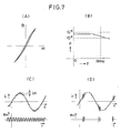
- the number of turns of said first winding 32 may be three and that of said second winding 33 ten, the characteristic curve of the core being approximately linear, as shown in Fig. 7A.
- this core 31 may vary according to the line to which it is applied, the requisite sensitivity, etc. When it is to be attached to a grounding, the inner diameter thereof may be as small as ca. 30mm.
- the signal line 34 is inserted into the annular core 31, and the high frequency component of the principal circuit current i1 flowing through this signal detection line 34 is detected.
- the principal circuit current i1 is composed of a high frequency current i H and a low frequency current i L , one superimposed on the other, the operation of discriminating the signal due to the high frequency current i H out of the principal circuit current i1 may be mathematically described as follows:
- the inductance with respect to f which is the frequency of the low frequency current and the inductance with respect to f n which is the frequency of the high frequency current are approximately equal to each other.
- the value of this inductance will be referred to as L.
- the internal voltage with the frequency f generated in the first winding 32 is roughly proportional to the inductive reactance X L
- the internal voltage with the frequency f n is roughly proportional to the inductive reactance X H
- Fig. 7C shows the relation between the principal circuit current i1 which in this case is a signal composed of a high frequency current i H superimposed on a sine wave and a detection signal voltage e H discriminated, on a time axis basis.
- Fig. 7D shows the detection signal voltage e H when a pulse is superimposed on the principal circuit current i1 which is a sine wave.
- Fig. 9 illustrates the above described signal discrimination method as applied to a supervisory system for checking any deterioration in insulation of a high-tension cable CA.
- the principal circuit current i1 is such as is obtained by combining the dominant wave of a charging and a leakage current of the insulator and a low frequency current i E which is the high frequency component thereof with a corona discharge current which is the deterioration signal for the insulator, a partial discharge current, or a high frequency current i P which is due to a kick-like pulse current
- the secondary winding 33 has a high inductive reactance to a high frequency current and a low inductive reactance to a low frequency current, so that the change in magnetic flux due to the low frequency current in the annular core 31 is cancelled.
- the high-tension cable CA also serves as the signal line 34. This arrangement makes it possible to detect not only deterioration in the insulator of the cable CA but also deterioration in insulation of the apparatuses connected to the cable CA.
- Figs. 11A and 11B show the signal discrimination method in accordance with this invention as applied to an apparatus for conducting insulating strength tests with DC or AC high voltage.
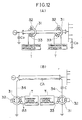
- Figs. 12A and 12B show the discrimination method of this invention as applied to a communication apparatus T using a power line.
- the communiction line is formed by utilizing the electrostatic capacity to ground C o of the system and the shielding wire of the power line.
- the apparatus in accordance with this invention is composed of a first winding 32 and a second winding 33 with a greater turn ratio than that of this first winding 32, both windings provided on an annular core 31 which has an approximately linear BH-characteristic, the magnetomotive force thereof being roughly proportional to the magnetic flux density, and whose magnetic permeability is approximately constant from the low frequency region to the high frequency region. Due to the above construction, this apparatus makes it possible to detect exclusively the high frequency component from the secondary winding 33.
Landscapes
- Engineering & Computer Science (AREA)
- Power Engineering (AREA)
- Measuring Instrument Details And Bridges, And Automatic Balancing Devices (AREA)
- Measurement Of Current Or Voltage (AREA)
- Testing Relating To Insulation (AREA)
- Measuring Magnetic Variables (AREA)
- Coils Or Transformers For Communication (AREA)
Priority Applications (1)
| Application Number | Priority Date | Filing Date | Title |
|---|---|---|---|
| AT88307259T ATE103742T1 (de) | 1987-08-07 | 1988-08-05 | Vorrichtung und verfahren zum diskriminieren von signalen. |
Applications Claiming Priority (6)
| Application Number | Priority Date | Filing Date | Title |
|---|---|---|---|
| JP197811/87 | 1987-08-07 | ||
| JP19781187A JP2521103B2 (ja) | 1987-08-07 | 1987-08-07 | 信号弁別器 |
| JP3049088A JP2514998B2 (ja) | 1988-02-12 | 1988-02-12 | 信号弁別器 |
| JP30490/88 | 1988-02-12 | ||
| JP47212/88 | 1988-02-29 | ||
| JP63047212A JPH01221929A (ja) | 1988-02-29 | 1988-02-29 | 信号弁別方法 |
Publications (3)
| Publication Number | Publication Date |
|---|---|
| EP0302746A2 true EP0302746A2 (fr) | 1989-02-08 |
| EP0302746A3 EP0302746A3 (en) | 1990-03-28 |
| EP0302746B1 EP0302746B1 (fr) | 1994-03-30 |
Family
ID=27286978
Family Applications (1)
| Application Number | Title | Priority Date | Filing Date |
|---|---|---|---|
| EP88307259A Expired - Lifetime EP0302746B1 (fr) | 1987-08-07 | 1988-08-05 | Appareil et méthode pour distinguer des signaux |
Country Status (6)
| Country | Link |
|---|---|
| US (1) | US4897561A (fr) |
| EP (1) | EP0302746B1 (fr) |
| KR (1) | KR910001385B1 (fr) |
| CN (1) | CN1016033B (fr) |
| CA (1) | CA1294014C (fr) |
| DE (1) | DE3888750T2 (fr) |
Cited By (2)
| Publication number | Priority date | Publication date | Assignee | Title |
|---|---|---|---|---|
| EP1003295A3 (fr) * | 1998-11-18 | 2000-09-13 | RegioCom GmbH | Filtre diplex à annulateur de flux, non saturant,pour communication par le réseau électrique |
| WO2003023991A1 (fr) * | 2001-09-13 | 2003-03-20 | Square D Company | Appareil et procede de transmission par courant porteur en ligne |
Families Citing this family (8)
| Publication number | Priority date | Publication date | Assignee | Title |
|---|---|---|---|---|
| CN1057649C (zh) * | 1993-08-19 | 2000-10-18 | 明碁电脑股份有限公司 | 具有磁滞现象的频率鉴别状态装置 |
| NL9400727A (nl) * | 1994-05-03 | 1995-12-01 | Gti Ind Automation Bv | Beveiligingssysteem met magnetische logica-schakelingen. |
| CH692161A5 (fr) * | 1997-07-04 | 2002-02-28 | Lem Liaisons Electron Mec | Capteur de courant. |
| JP4708145B2 (ja) * | 2005-10-05 | 2011-06-22 | パナソニック株式会社 | 電力線通信装置 |
| DE102009052632A1 (de) * | 2009-11-10 | 2011-05-12 | Converteam Technology Ltd., Warwickshire | Elektrische Schaltung zur Erzeugung elektrischer Energie |
| JP6272185B2 (ja) * | 2014-08-25 | 2018-01-31 | 三菱電機株式会社 | 配線用コア構造、半導体評価装置及び半導体装置 |
| CN105845405B (zh) * | 2016-06-02 | 2018-06-12 | 福州大学 | 一种分立磁性元件耦合电路及其控制方法 |
| CN113471704A (zh) * | 2021-07-15 | 2021-10-01 | 贵州电网有限责任公司 | 一种接收故障绝缘子高压放电电磁波的磁天线及调试方法 |
Family Cites Families (9)
| Publication number | Priority date | Publication date | Assignee | Title |
|---|---|---|---|---|
| DE690731C (de) * | 1932-03-25 | 1940-05-06 | Siemens & Halske Akt Ges | Einrichtung fuer den Nachrichtenverkehr mit Traegerwellen laengs Starkstromleitungen |
| US2838688A (en) * | 1956-10-22 | 1958-06-10 | North American Aviation Inc | Saturable phase detector |
| US2966595A (en) * | 1957-12-31 | 1960-12-27 | Ibm | Pulse sensing system |
| US3104373A (en) * | 1959-05-20 | 1963-09-17 | Lenkurt Electric Company Inc | Selective frequency detector |
| US3183498A (en) * | 1961-10-02 | 1965-05-11 | Itt | Line-monitor circuit |
| IT962385B (it) * | 1972-07-04 | 1973-12-20 | Siemens Spa Italiana | Sistema di disaccoppiamento del segnale ad alta frequenza dalla corrente a frequenza industriale in sistemi utilizzanti mezzi tra smissivi comuni |
| GB2091976B (en) * | 1980-12-12 | 1984-12-05 | Ecs Energy Conversation System | Electricity supply signalling |
| JPS58179034A (ja) * | 1982-04-14 | 1983-10-20 | Sharp Corp | デ−タ伝送システム |
| GB2148643B (en) * | 1983-11-07 | 1988-03-16 | Emlux Ltd | Filtering electrical signals |
-
1988
- 1988-08-05 KR KR1019880009996A patent/KR910001385B1/ko not_active Expired
- 1988-08-05 US US07/228,579 patent/US4897561A/en not_active Expired - Fee Related
- 1988-08-05 DE DE3888750T patent/DE3888750T2/de not_active Expired - Fee Related
- 1988-08-05 EP EP88307259A patent/EP0302746B1/fr not_active Expired - Lifetime
- 1988-08-05 CA CA000573969A patent/CA1294014C/fr not_active Expired - Lifetime
- 1988-08-06 CN CN88104897A patent/CN1016033B/zh not_active Expired
Cited By (3)
| Publication number | Priority date | Publication date | Assignee | Title |
|---|---|---|---|---|
| EP1003295A3 (fr) * | 1998-11-18 | 2000-09-13 | RegioCom GmbH | Filtre diplex à annulateur de flux, non saturant,pour communication par le réseau électrique |
| US6177849B1 (en) | 1998-11-18 | 2001-01-23 | Oneline Ag | Non-saturating, flux cancelling diplex filter for power line communications |
| WO2003023991A1 (fr) * | 2001-09-13 | 2003-03-20 | Square D Company | Appareil et procede de transmission par courant porteur en ligne |
Also Published As
| Publication number | Publication date |
|---|---|
| DE3888750T2 (de) | 1994-07-14 |
| KR910001385B1 (ko) | 1991-03-04 |
| CN1016033B (zh) | 1992-03-25 |
| EP0302746A3 (en) | 1990-03-28 |
| KR890004483A (ko) | 1989-04-22 |
| DE3888750D1 (de) | 1994-05-05 |
| US4897561A (en) | 1990-01-30 |
| CN1031165A (zh) | 1989-02-15 |
| EP0302746B1 (fr) | 1994-03-30 |
| CA1294014C (fr) | 1992-01-07 |
Similar Documents
| Publication | Publication Date | Title |
|---|---|---|
| EP0544646B1 (fr) | Dispositif pour évaluer l'état d'isolation | |
| US5933012A (en) | Device for sensing of electric discharges in a test object | |
| US4914382A (en) | High voltage measuring circuit coupled to the capacitive grounding tap bushing of an HV device | |
| Nanyan et al. | The rogowski coil sensor in high current application: A review | |
| Anderson | Wide frequency range current transformers | |
| EP0302746B1 (fr) | Appareil et méthode pour distinguer des signaux | |
| US11650228B1 (en) | Very-wide-bandwidth current sensor | |
| US4280093A (en) | Zero-current detector for high voltage DC transmission line | |
| JP2831355B2 (ja) | 絶縁状態の検知方法 | |
| EP0312050A2 (fr) | Circuit de mesure haute tension couplé au plot de mise à la terre capacitive d'un dispositif haute tension | |
| JPH07119782B2 (ja) | 電気機器およびケ−ブルの絶縁劣化検出装置 | |
| JP2514998B2 (ja) | 信号弁別器 | |
| JP2521103B2 (ja) | 信号弁別器 | |
| JP2869067B2 (ja) | 絶縁状態の検知装置 | |
| Bagheri et al. | On-load tap-changer influence on frequency response analysis of transformer: a case study | |
| RU2292054C1 (ru) | Устройство для измерения переменных магнитных полей | |
| CN1029033C (zh) | 绝缘状态的检测方法及装置 | |
| JP2836743B2 (ja) | 絶縁状態の検知方法、及びその検知装置 | |
| JPH01221929A (ja) | 信号弁別方法 | |
| CA1157095A (fr) | Detecteur de courants nuls pour ligne de transmission a haute tension continue | |
| JP2001242197A (ja) | 電流検出器 | |
| JPWO2020174521A1 (ja) | 電圧変成器 | |
| MXPA97003265A (en) | A device to detect electric shock in one object of pru | |
| JPH0252830B2 (fr) |
Legal Events
| Date | Code | Title | Description |
|---|---|---|---|
| PUAI | Public reference made under article 153(3) epc to a published international application that has entered the european phase |
Free format text: ORIGINAL CODE: 0009012 |
|
| AK | Designated contracting states |
Kind code of ref document: A2 Designated state(s): AT BE CH DE ES FR GB GR IT LI LU NL SE |
|
| PUAL | Search report despatched |
Free format text: ORIGINAL CODE: 0009013 |
|
| RHK1 | Main classification (correction) |
Ipc: H04B 3/56 |
|
| AK | Designated contracting states |
Kind code of ref document: A3 Designated state(s): AT BE CH DE ES FR GB GR IT LI LU NL SE |
|
| 17P | Request for examination filed |
Effective date: 19900703 |
|
| 17Q | First examination report despatched |
Effective date: 19921211 |
|
| GRAA | (expected) grant |
Free format text: ORIGINAL CODE: 0009210 |
|
| AK | Designated contracting states |
Kind code of ref document: B1 Designated state(s): AT BE CH DE ES FR GB GR IT LI LU NL SE |
|
| PG25 | Lapsed in a contracting state [announced via postgrant information from national office to epo] |
Ref country code: SE Free format text: THE PATENT HAS BEEN ANNULLED BY A DECISION OF A NATIONAL AUTHORITY Effective date: 19940330 Ref country code: LI Effective date: 19940330 Ref country code: GR Free format text: LAPSE BECAUSE OF FAILURE TO SUBMIT A TRANSLATION OF THE DESCRIPTION OR TO PAY THE FEE WITHIN THE PRESCRIBED TIME-LIMIT Effective date: 19940330 Ref country code: ES Free format text: THE PATENT HAS BEEN ANNULLED BY A DECISION OF A NATIONAL AUTHORITY Effective date: 19940330 Ref country code: CH Effective date: 19940330 Ref country code: BE Effective date: 19940330 Ref country code: AT Effective date: 19940330 |
|
| REF | Corresponds to: |
Ref document number: 103742 Country of ref document: AT Date of ref document: 19940415 Kind code of ref document: T |
|
| ITF | It: translation for a ep patent filed | ||
| ET | Fr: translation filed | ||
| REF | Corresponds to: |
Ref document number: 3888750 Country of ref document: DE Date of ref document: 19940505 |
|
| REG | Reference to a national code |
Ref country code: CH Ref legal event code: PL |
|
| PG25 | Lapsed in a contracting state [announced via postgrant information from national office to epo] |
Ref country code: LU Free format text: LAPSE BECAUSE OF NON-PAYMENT OF DUE FEES Effective date: 19940831 |
|
| PLBE | No opposition filed within time limit |
Free format text: ORIGINAL CODE: 0009261 |
|
| STAA | Information on the status of an ep patent application or granted ep patent |
Free format text: STATUS: NO OPPOSITION FILED WITHIN TIME LIMIT |
|
| 26N | No opposition filed | ||
| PGFP | Annual fee paid to national office [announced via postgrant information from national office to epo] |
Ref country code: GB Payment date: 19970728 Year of fee payment: 10 |
|
| PGFP | Annual fee paid to national office [announced via postgrant information from national office to epo] |
Ref country code: FR Payment date: 19970811 Year of fee payment: 10 Ref country code: DE Payment date: 19970811 Year of fee payment: 10 |
|
| PGFP | Annual fee paid to national office [announced via postgrant information from national office to epo] |
Ref country code: NL Payment date: 19970826 Year of fee payment: 10 |
|
| PG25 | Lapsed in a contracting state [announced via postgrant information from national office to epo] |
Ref country code: GB Free format text: LAPSE BECAUSE OF NON-PAYMENT OF DUE FEES Effective date: 19980805 |
|
| REG | Reference to a national code |
Ref country code: FR Ref legal event code: CD |
|
| NLT1 | Nl: modifications of names registered in virtue of documents presented to the patent office pursuant to art. 16 a, paragraph 1 |
Owner name: MITSUI CHEMICALS, INC. |
|
| PG25 | Lapsed in a contracting state [announced via postgrant information from national office to epo] |
Ref country code: NL Free format text: LAPSE BECAUSE OF NON-PAYMENT OF DUE FEES Effective date: 19990301 |
|
| GBPC | Gb: european patent ceased through non-payment of renewal fee |
Effective date: 19980805 |
|
| PG25 | Lapsed in a contracting state [announced via postgrant information from national office to epo] |
Ref country code: FR Free format text: LAPSE BECAUSE OF NON-PAYMENT OF DUE FEES Effective date: 19990430 |
|
| NLV4 | Nl: lapsed or anulled due to non-payment of the annual fee |
Effective date: 19990301 |
|
| PG25 | Lapsed in a contracting state [announced via postgrant information from national office to epo] |
Ref country code: DE Free format text: LAPSE BECAUSE OF NON-PAYMENT OF DUE FEES Effective date: 19990601 |
|
| REG | Reference to a national code |
Ref country code: FR Ref legal event code: ST |
|
| PG25 | Lapsed in a contracting state [announced via postgrant information from national office to epo] |
Ref country code: IT Free format text: LAPSE BECAUSE OF NON-PAYMENT OF DUE FEES;WARNING: LAPSES OF ITALIAN PATENTS WITH EFFECTIVE DATE BEFORE 2007 MAY HAVE OCCURRED AT ANY TIME BEFORE 2007. THE CORRECT EFFECTIVE DATE MAY BE DIFFERENT FROM THE ONE RECORDED. Effective date: 20050805 |