EP0302806A1 - Vorrichtung zum Spannen und Halten von Elementen, die durch Kleben, Heften, Nageln oder Nieten zusammengefügt werden sollen - Google Patents
Vorrichtung zum Spannen und Halten von Elementen, die durch Kleben, Heften, Nageln oder Nieten zusammengefügt werden sollen Download PDFInfo
- Publication number
- EP0302806A1 EP0302806A1 EP88440065A EP88440065A EP0302806A1 EP 0302806 A1 EP0302806 A1 EP 0302806A1 EP 88440065 A EP88440065 A EP 88440065A EP 88440065 A EP88440065 A EP 88440065A EP 0302806 A1 EP0302806 A1 EP 0302806A1
- Authority
- EP
- European Patent Office
- Prior art keywords
- axis
- button
- casing
- ribbon
- pinion
- Prior art date
- Legal status (The legal status is an assumption and is not a legal conclusion. Google has not performed a legal analysis and makes no representation as to the accuracy of the status listed.)
- Granted
Links
Images
Classifications
-
- B—PERFORMING OPERATIONS; TRANSPORTING
- B25—HAND TOOLS; PORTABLE POWER-DRIVEN TOOLS; MANIPULATORS
- B25B—TOOLS OR BENCH DEVICES NOT OTHERWISE PROVIDED FOR, FOR FASTENING, CONNECTING, DISENGAGING, OR HOLDING
- B25B1/00—Vices
- B25B1/20—Vices for clamping work of special profile, e.g. pipes
- B25B1/205—Vices of the chain or strip type
-
- B—PERFORMING OPERATIONS; TRANSPORTING
- B25—HAND TOOLS; PORTABLE POWER-DRIVEN TOOLS; MANIPULATORS
- B25B—TOOLS OR BENCH DEVICES NOT OTHERWISE PROVIDED FOR, FOR FASTENING, CONNECTING, DISENGAGING, OR HOLDING
- B25B5/00—Clamps
- B25B5/14—Clamps for work of special profile
- B25B5/147—Clamps for work of special profile for pipes
Definitions
- the present invention relates to the field of assembling and holding frames and other elements to be held by clamping during their final assembly, generally by bonding, and relates to a device for clamping and holding elements to be assembled by gluing, stapling, nailing or riveting.
- the present invention aims to overcome these drawbacks.
- the operating axis is a disengageable axis surmounted by an operating button displaceable on said axis, and which can be locked in various positions of displacement on this axis, this operating button being provided, in addition, with a toothed pinion which can cooperate, in a position of displacement of the button, with a pinion integral with the split axis of the ribbon winding reel, and in another position of displacement of the button, with a pawl loaded by spring, the ribbon wound on the reel crossing the operating axis which is split for this purpose, so as to form a loop leaving the casing.
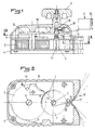
- the device for clamping and holding elements to be assembled which essentially consists of a tape 1 wound at one end on a spool 2 and fixed at its other end to an operating shaft 3, the assembly being mounted in a protective casing 4, and by parts 5 for recovery and positioning at the corners, and characterized in that the operating axis 3 is in the form of a disengageable axis on which is mounted, in a displaceable manner, an operating button 6 which can be locked in various displacement positions on the axis 3.
- the operating button 6 is also provided with a toothed pinion 7 which can cooperate, on the one hand, in a position of displacement of the button, with a pinion 8 integral with the split axis 9 of the coil 2 for winding of the ribbon 1, and, on the other hand, in another position of displacement of the button 6, with a pawl 10 loaded by a spring 11.
- the ribbon 1, wound on the reel 2 crosses the operating axis 3 , which has, for this purpose, a slot 12, so as to form a loop 14 emerging from the casing 4.
- the split axes 3 and 9, for maneuvering and for the spool 2, are guided in rotation between two walls of the casing 4, which simultaneously maintain the spool 2 and guide the ribbon 1.
- the operating shaft 3 is provided at its end facing the operating button 6, on the one hand, with a male clutch means 13 cooperating with a female clutch means 13 ′, of corresponding shape, and , on the other hand, above the means 13, in the direction of the button 6, of a hub 15 for guiding the latter, and the pawl 10 is mounted on the wall of the casing 4 on the side of the means 13 of the axis 3.
- the pinion 8 of the axis 9 of the coil 2 advantageously extends above the pawl 10 with a spacing from the latter at least equal to 1 thickness of the pinion 7 of the button 6, and the latter is either loaded by a spring tending to maintain it in one of its extreme positions on the hub 15 of the axis 3, or provided with a stop means 16 in position on the hub 15, in each intermediate position of displacement on the axis 2, such as a spring loaded ball catch, or the like.
- This embodiment allows, in the case of a button 6 loaded by spring in one of its directions of movement, to know with certainty in which position is the pinion 7 of the button 6, namely, meshing with the pinion 8 of the axis 9 or with the pawl 10, an intermediate position between these two allowing the release of the coil 2 simultaneously with that of the axis 3, and, in the case of a button 6 provided with a stop means 16 in position on the hub 15, ensuring the exact positioning of the button 6 in each extreme and intermediate position.
- the strands of the loop 14 emerging from the casing 4 are guided between a spacer element 17, forming part of the casing 4 and simultaneously forming a recovery and positioning angle for a corner of the elements to be assembled, and two cylinders 18 integral with the casing 4, so that each strand passes between a cylinder 18 and the element 17, and, at the exit of the strands of the loop 14, the casing 4 is provided, in addition, with a multiple imprint 19 consisting of several segments of different inclination with respect to the face of the casing and allowing the support of elements to abut at various angles.
- the multiple imprint 19, as well as the parts 5 for taking up and positioning at the corners are advantageously provided with at least one rim for guiding the ribbon 1, the parts 5 possibly being provided with a vertical elastic segment 20 intended to grip the ribbon 1.
- the device according to the invention operates in the following manner:
- the ribbon 1 can be unwound from the reel 2 through the slot 12 of the operating shaft 3 so as to allow opening of the loop 14 sufficient to ensure mounting around the elements to be assembled, for example to form a frame.
- the parts 5 are then threaded by their vertical segment 20 onto the ribbon 1 and placed at the corners of the frame, or the like, to be produced, and the button 6 is moved to an extreme position in which its toothed pinion 7 is in contact with the pinion 8 of the axis 9 of the coil 2.
- the ribbon 1 is then rewound on the coil 2 until a low tension is obtained, then the button 6 is moved on the hub 15 of the axis 3 in order to bring its female dog clutch 13 ′ in shape cooperation with the male dog clutch 13 of said axis 3.
- the final tightening of the elements to be assembled is carried out, by simultaneous advance of the two strands of the ribbon, this tightening being maintained by locking the axis 3, by cooperation of the pawl 10 with the pinion toothed 7 of the button 6.
- the ribbon 1 one end of which is fixed to the operating shaft 3 and which also crosses the slot 12 of the latter, is wound, simultaneously with the end fixed to the axis 3, on the latter, so that the loop 14 formed outside the casing is tensioned simultaneously compassion and equally, by its two strands penetrating into the casing 4.
- the part of the ribbon 1 extending between the coil 2 and the axis 3 can be wound, then, freely around the axis 3, because that the axis 9 of the coil 2 is no longer loaded in any way.
- the device described above has been used more particularly as a device for clamping elements to be assembled, however, it is also usable to simple and rational way, as a tightening strap.
- this device it is possible to produce a device making it possible to hold and tighten elements to be assembled together, while ensuring, during tightening, a good distribution of the tightening force by simultaneous advance of the two strands of the loop enclosing said elements to be assembled.
- this device is of particularly simple constitution and has a minimum of operating parts, so that its reliability is increased compared to known devices of this type.
Landscapes
- Engineering & Computer Science (AREA)
- Mechanical Engineering (AREA)
- Portable Nailing Machines And Staplers (AREA)
- Winding Of Webs (AREA)
- Insertion Pins And Rivets (AREA)
- Connection Of Plates (AREA)
- Impression-Transfer Materials And Handling Thereof (AREA)
- Dovetailed Work, And Nailing Machines And Stapling Machines For Wood (AREA)
Priority Applications (1)
| Application Number | Priority Date | Filing Date | Title |
|---|---|---|---|
| AT88440065T ATE57490T1 (de) | 1987-08-04 | 1988-08-03 | Vorrichtung zum spannen und halten von elementen, die durch kleben, heften, nageln oder nieten zusammengefuegt werden sollen. |
Applications Claiming Priority (2)
| Application Number | Priority Date | Filing Date | Title |
|---|---|---|---|
| FR8711178A FR2619041B1 (fr) | 1987-08-04 | 1987-08-04 | Dispositif pour le serrage et le maintien d'elements a assembler par collage, agrafage, clouage ou rivetage |
| FR8711178 | 1987-08-04 |
Publications (2)
| Publication Number | Publication Date |
|---|---|
| EP0302806A1 true EP0302806A1 (de) | 1989-02-08 |
| EP0302806B1 EP0302806B1 (de) | 1990-10-17 |
Family
ID=9353953
Family Applications (1)
| Application Number | Title | Priority Date | Filing Date |
|---|---|---|---|
| EP88440065A Expired - Lifetime EP0302806B1 (de) | 1987-08-04 | 1988-08-03 | Vorrichtung zum Spannen und Halten von Elementen, die durch Kleben, Heften, Nageln oder Nieten zusammengefügt werden sollen |
Country Status (4)
| Country | Link |
|---|---|
| EP (1) | EP0302806B1 (de) |
| AT (1) | ATE57490T1 (de) |
| DE (1) | DE3860823D1 (de) |
| FR (1) | FR2619041B1 (de) |
Citations (6)
| Publication number | Priority date | Publication date | Assignee | Title |
|---|---|---|---|---|
| DE181133C (de) * | 1900-01-01 | |||
| DE457013C (de) * | 1928-03-07 | Julius Klement | Rahmenspannvorrichtung | |
| GB1006056A (en) * | 1963-07-17 | 1965-09-29 | John Galpin | Improvements in and relating to clamps or cramps |
| US3661378A (en) * | 1969-09-30 | 1972-05-09 | Crawford Fitting Co | Gripping device |
| DE8511115U1 (de) * | 1985-04-16 | 1985-09-19 | Fa. Friedrich Küpper, 5531 Berlingen | Vorrichtung zum Spannen von Bilderrahmen |
| DE3527986A1 (de) * | 1985-08-03 | 1986-04-24 | Peter 8163 Bayrischzell Santo | Spannvorrichtung zum zusammenleimen von bilderrahmen oder gehrungsschnitten |
-
1987
- 1987-08-04 FR FR8711178A patent/FR2619041B1/fr not_active Expired - Lifetime
-
1988
- 1988-08-03 DE DE8888440065T patent/DE3860823D1/de not_active Expired - Fee Related
- 1988-08-03 EP EP88440065A patent/EP0302806B1/de not_active Expired - Lifetime
- 1988-08-03 AT AT88440065T patent/ATE57490T1/de active
Patent Citations (6)
| Publication number | Priority date | Publication date | Assignee | Title |
|---|---|---|---|---|
| DE181133C (de) * | 1900-01-01 | |||
| DE457013C (de) * | 1928-03-07 | Julius Klement | Rahmenspannvorrichtung | |
| GB1006056A (en) * | 1963-07-17 | 1965-09-29 | John Galpin | Improvements in and relating to clamps or cramps |
| US3661378A (en) * | 1969-09-30 | 1972-05-09 | Crawford Fitting Co | Gripping device |
| DE8511115U1 (de) * | 1985-04-16 | 1985-09-19 | Fa. Friedrich Küpper, 5531 Berlingen | Vorrichtung zum Spannen von Bilderrahmen |
| DE3527986A1 (de) * | 1985-08-03 | 1986-04-24 | Peter 8163 Bayrischzell Santo | Spannvorrichtung zum zusammenleimen von bilderrahmen oder gehrungsschnitten |
Also Published As
| Publication number | Publication date |
|---|---|
| EP0302806B1 (de) | 1990-10-17 |
| DE3860823D1 (de) | 1990-11-22 |
| ATE57490T1 (de) | 1990-11-15 |
| FR2619041B1 (fr) | 1990-01-05 |
| FR2619041A1 (fr) | 1989-02-10 |
Similar Documents
| Publication | Publication Date | Title |
|---|---|---|
| EP0368798A1 (de) | Seilspanner mit Wickeltrommel für Skischuh | |
| FR2561878A1 (fr) | Dispositif de fermeture, en particulier pour des chaussures de ski a ouverture arriere | |
| FR2653549A1 (fr) | Metre a ruban reenroulable a connexion perfectionnee entre ressort et ruban. | |
| FR2653548A1 (fr) | Metre a ruban reenroulable a connexion perfectionnee entre ressort et moyeu. | |
| FR2489155A1 (fr) | Dispositif de blocage du ruban de ceinture pour les ceintures de securite des vehicules automobiles | |
| CH447628A (fr) | Instrument de mesures linéares à ruban souple enroulé à l'intérieur d'un boîtier et à réenroulement automatique | |
| FR2560922A1 (fr) | Dispositif pour empecher l'application d'une tension excessive au moteur a ressort d'un store de fenetre | |
| FR2477420A1 (fr) | Enrouleur automatique pour une ceinture de securite | |
| EP0427932A1 (de) | Rollende lineare Messung mit Multiplikator | |
| EP0255788A1 (de) | Sicherheitsgurtaufroller | |
| FR2776612A1 (fr) | Perfectionnement au dispositif de montage d'un moyeu de roue d'un deux roues | |
| EP0302806B1 (de) | Vorrichtung zum Spannen und Halten von Elementen, die durch Kleben, Heften, Nageln oder Nieten zusammengefügt werden sollen | |
| CH668763A5 (fr) | Appareil portatif pour l'application d'adhesif-transfert. | |
| FR2482542A1 (fr) | Mecanisme de commande de frein a main | |
| FR2775158A1 (fr) | Taille-haie equipe d'un moteur thermique a demarrer manuellement et d'un frein a ruban de securite | |
| FR2525084A1 (fr) | Casque de protection avec dispositif de reglage de jugulaire | |
| CH629360A5 (fr) | Moulinet de peche. | |
| EP0094905A1 (de) | Farbbandkassette für Schreibmaschinen | |
| FR2466258A1 (fr) | Enrouleur de ceinture de securite a blocage d'enroulement selectif | |
| FR2569991A1 (fr) | Dispositif antivol de poche pour une paire de skis | |
| FR2564395A1 (fr) | Enrouleur de ceinture de securite | |
| CH650752A5 (en) | Manual clamping device | |
| EP0096137A1 (de) | Aufwickelvorrichtung in Gehäuse | |
| FR2635096A1 (fr) | Dispositif d'enroulement pour tirant a cable, en particulier pour chaussures de ski | |
| FR2617819A1 (fr) | Dispositif derouleur de bobines de films en matiere plastique etirable et auto-adhesive pour fardelage de produits divers |
Legal Events
| Date | Code | Title | Description |
|---|---|---|---|
| PUAI | Public reference made under article 153(3) epc to a published international application that has entered the european phase |
Free format text: ORIGINAL CODE: 0009012 |
|
| AK | Designated contracting states |
Kind code of ref document: A1 Designated state(s): AT BE CH DE ES GB GR IT LI LU NL SE |
|
| 17P | Request for examination filed |
Effective date: 19890221 |
|
| 17Q | First examination report despatched |
Effective date: 19900209 |
|
| GRAA | (expected) grant |
Free format text: ORIGINAL CODE: 0009210 |
|
| AK | Designated contracting states |
Kind code of ref document: B1 Designated state(s): AT BE CH DE ES GB GR IT LI LU NL SE |
|
| PG25 | Lapsed in a contracting state [announced via postgrant information from national office to epo] |
Ref country code: IT Free format text: LAPSE BECAUSE OF FAILURE TO SUBMIT A TRANSLATION OF THE DESCRIPTION OR TO PAY THE FEE WITHIN THE PRESCRIBED TIME-LIMIT;WARNING: LAPSES OF ITALIAN PATENTS WITH EFFECTIVE DATE BEFORE 2007 MAY HAVE OCCURRED AT ANY TIME BEFORE 2007. THE CORRECT EFFECTIVE DATE MAY BE DIFFERENT FROM THE ONE RECORDED. Effective date: 19901017 Ref country code: ES Free format text: THE PATENT HAS BEEN ANNULLED BY A DECISION OF A NATIONAL AUTHORITY Effective date: 19901017 Ref country code: GR Free format text: LAPSE BECAUSE OF FAILURE TO SUBMIT A TRANSLATION OF THE DESCRIPTION OR TO PAY THE FEE WITHIN THE PRESCRIBED TIME-LIMIT Effective date: 19901017 Ref country code: NL Effective date: 19901017 Ref country code: AT Effective date: 19901017 Ref country code: SE Effective date: 19901017 |
|
| REF | Corresponds to: |
Ref document number: 57490 Country of ref document: AT Date of ref document: 19901115 Kind code of ref document: T |
|
| REF | Corresponds to: |
Ref document number: 3860823 Country of ref document: DE Date of ref document: 19901122 |
|
| GBT | Gb: translation of ep patent filed (gb section 77(6)(a)/1977) | ||
| NLV1 | Nl: lapsed or annulled due to failure to fulfill the requirements of art. 29p and 29m of the patents act | ||
| PLBE | No opposition filed within time limit |
Free format text: ORIGINAL CODE: 0009261 |
|
| STAA | Information on the status of an ep patent application or granted ep patent |
Free format text: STATUS: NO OPPOSITION FILED WITHIN TIME LIMIT |
|
| 26N | No opposition filed | ||
| PGFP | Annual fee paid to national office [announced via postgrant information from national office to epo] |
Ref country code: GB Payment date: 19920805 Year of fee payment: 5 |
|
| PGFP | Annual fee paid to national office [announced via postgrant information from national office to epo] |
Ref country code: LU Payment date: 19920820 Year of fee payment: 5 |
|
| PGFP | Annual fee paid to national office [announced via postgrant information from national office to epo] |
Ref country code: BE Payment date: 19920902 Year of fee payment: 5 |
|
| PGFP | Annual fee paid to national office [announced via postgrant information from national office to epo] |
Ref country code: CH Payment date: 19921130 Year of fee payment: 5 |
|
| EPTA | Lu: last paid annual fee | ||
| PG25 | Lapsed in a contracting state [announced via postgrant information from national office to epo] |
Ref country code: LU Free format text: LAPSE BECAUSE OF NON-PAYMENT OF DUE FEES Effective date: 19930803 Ref country code: GB Effective date: 19930803 |
|
| PG25 | Lapsed in a contracting state [announced via postgrant information from national office to epo] |
Ref country code: BE Effective date: 19930831 Ref country code: CH Effective date: 19930831 Ref country code: LI Effective date: 19930831 |
|
| BERE | Be: lapsed |
Owner name: SOFRA-SER SOC. FRANCAISE DE SERRAGE S.A.R.L. Effective date: 19930831 |
|
| GBPC | Gb: european patent ceased through non-payment of renewal fee |
Effective date: 19930803 |
|
| REG | Reference to a national code |
Ref country code: CH Ref legal event code: PL |
|
| PGFP | Annual fee paid to national office [announced via postgrant information from national office to epo] |
Ref country code: DE Payment date: 20010828 Year of fee payment: 14 |
|
| PG25 | Lapsed in a contracting state [announced via postgrant information from national office to epo] |
Ref country code: DE Free format text: LAPSE BECAUSE OF NON-PAYMENT OF DUE FEES Effective date: 20030301 |