EP0302942A1 - Vorderrahmen für radlader - Google Patents
Vorderrahmen für radlader Download PDFInfo
- Publication number
- EP0302942A1 EP0302942A1 EP88901325A EP88901325A EP0302942A1 EP 0302942 A1 EP0302942 A1 EP 0302942A1 EP 88901325 A EP88901325 A EP 88901325A EP 88901325 A EP88901325 A EP 88901325A EP 0302942 A1 EP0302942 A1 EP 0302942A1
- Authority
- EP
- European Patent Office
- Prior art keywords
- frame
- pivot
- front frame
- boom
- upper frame
- Prior art date
- Legal status (The legal status is an assumption and is not a legal conclusion. Google has not performed a legal analysis and makes no representation as to the accuracy of the status listed.)
- Granted
Links
- 238000003466 welding Methods 0.000 description 9
- 238000005266 casting Methods 0.000 description 3
- 238000010276 construction Methods 0.000 description 3
- 230000003014 reinforcing effect Effects 0.000 description 3
- 230000008602 contraction Effects 0.000 description 1
- 230000003247 decreasing effect Effects 0.000 description 1
- 230000007547 defect Effects 0.000 description 1
- 238000003754 machining Methods 0.000 description 1
- 238000004519 manufacturing process Methods 0.000 description 1
- 239000002184 metal Substances 0.000 description 1
- 238000007711 solidification Methods 0.000 description 1
- 230000008023 solidification Effects 0.000 description 1
Images
Classifications
-
- E—FIXED CONSTRUCTIONS
- E02—HYDRAULIC ENGINEERING; FOUNDATIONS; SOIL SHIFTING
- E02F—DREDGING; SOIL-SHIFTING
- E02F9/00—Component parts of dredgers or soil-shifting machines, not restricted to one of the kinds covered by groups E02F3/00 - E02F7/00
- E02F9/08—Superstructures; Supports for superstructures
- E02F9/0841—Articulated frame, i.e. having at least one pivot point between two travelling gear units
Definitions
- This invention relates to a so-called articulate type wheel mounted loader in which the front and rear sides are separated and interconnected, and more particularly an improvement of a front frame that constitutes the front part of the wheel mounted type loader.
- Fig. 3 is a diagrammatic side view showing a conventional wheel mounted loader.
- This wheel mounted loader 1 is a so-called articulated type wheel mounted loader and is constituted by a front frame 2 which constitutes the essential portion of the front portion of the wheel and a rear frame 3 separate from the front frame 2 and constitutes the essential portion of the rear portion of the frame. These front frame 2 and the rear frame 3 are interconnected by a center hinge pin 4 as shown in Fig. 4 taken along a line A-A in Fig. 3.
- Reference numerals 4 and 5 shown in Fig. 3 respectively show the front wheel and the rear wheel of the wheel mounted type loader 1, while reference numerals 6, 7, 8 and 9 respectively show a bucket, a boom, a bucket cylinder and a boom cylinder.
- Reference numeral 10 shown in Fig. 4 represents steering cylinders, while 11 represents pivot pins of the steering cylinders.
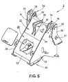
- Fig. 5 is a diagrammatic perspective view showing a prior art front frame 2.
- the front frame 2 is constituted by a lower frame 20 constituting the lower portion of the front frame 2, and a upper frame 21 mounted on the upper portion of the lower frame 20 and formed with various bearing openings.
- the lower frame 20 is constituted by a front face plate 22 covering the front surface of the front frame 2, and a pair of side plates 23 covering the side surfaces
- the upper frame 21 is constituted by a upper plate 24 covering the upper portion of the front frame 2, and a pair of side plates 25 which are separate from the side plates 23 and arranged on both sides of the upper portions of the side plates 23.
- the pair of side plates 25 are welded to the side surfaces of the side plates 23 through reinforcing ribs 26, whereby the side plates 25 are securely fastened to the side surfaces of the side plate 23.
- reference numeral 30 designates-a pair of boom pivots formed through the side plates 23 and 25 respectively
- 31 designates a pair of boom cylinder pivot pins provided for the side plates 25
- 32 designates bucket cylinder pivots formed at the center of the upper plate 24.
- the upper portion of the front frame is constituted by at least one rigid plate thicker than other parts constituting the front frame and formed with a bucket cylinder pivot and a boom pivot, and a pair of plate shaped boom cylinder pivot members connected to the opposite ends of the single plate and formed with boom cylinder pivots, thereby integrating the upper frame as a unit constituting the upper portion of the front frame.
- the front frame can be assembled by merely mounting the integrated upper frame of the front frame on the lower frame constituting the lower portion of the front frame and then welding the upper frame and the lower frame together. Consequently, the number of parts of the upper frame constituting the upper portion of the frame can be reduced so that the number of welds applied at the time of assembling the entire front frame can also be reduced.
- the upper plate is integrated by using the single plate of the upper plate as the base, it becomes possible to integrally provide the pivot openings thereby enabling to obtain a low cost wheel mounted type loader having improved center accuracy of respective pivots as well as high reliability and durability.
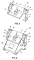
- Fig. 1 is a diagrammatic perspective view of the upper frame 40 constituting the upper portion of the front frame according to this invention in which parts identical to those shown in Fig. 5 are designated by the same reference numerals.
- the upper frame 40 is constituted by a rigid single plate 41 thicker than other component parts of the front frame to be described later, and a pair of boom cylinder pivot members 42 disposed beneath the opposite ends of the single plate 41.
- the upper frame 40 is constituted by extremely smaller number of parts than the prior art upper frame.
- the boom cylinder pivot member 42 is made of a member having an L shaped cross-section.
- the boom cylinder pivot member 42 is formed integral with the single plate 41 by welding or integral casting.
- a pair of brackets 43 respectively formed with a bucket cylinder pivot 32 are secured to the upper surface 41a of the single plate 41 by welding or integral casting.
- a pair of brackets 44 each formed with a beam pivot 30 are secured to the opposite ends 41b and 41c of the upper surface 41a of the single plate 41 by welding or integral casting.
- pivot openings can be formed for the brackets 43, 44 and boom cylinder pivot members 42 from their sides by a boring tool such as a boring machine, not shown. For this reason, it is possible to provide the pair of brackets 43 with bucket cylinder pivots 32 having a high center accuracy. Furthermore, beam pivots 30 each having a high center accuracy can be formed for the pair of brackets 44 and boom cylinder pivots 31 each having a high center accuracy can be provided for the pair of boom cylinder pivot members 42. As a result, by inserting pivot pins of booms or cylinders, not shown, into respective pivots, since the center accuracies of respective pivots are high, one side wear of the pivot pins of respective pivots and booms or cylinders, etc. will not occur. This greatly improves the accuracy and durability of the wheel mounted type loader.
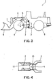
- Reference numeral 23a shown in Fig. 2 represents a shoulders formed at the upper portion of the side plate 23 constituting the lower plate 20. These shoulders 23a engage end portions 41b and 41c of the single plate 41 constituting the upper frame 40 so as to position the single plate 41 on the lower frame 20.
- the front frame embodying this invention is suitable for use in a wheel mounted type loader requiring reliability and durability.
Landscapes
- Engineering & Computer Science (AREA)
- Mining & Mineral Resources (AREA)
- Civil Engineering (AREA)
- General Engineering & Computer Science (AREA)
- Structural Engineering (AREA)
- Shovels (AREA)
Applications Claiming Priority (2)
| Application Number | Priority Date | Filing Date | Title |
|---|---|---|---|
| JP1429387 | 1987-02-04 | ||
| JP14293/87U | 1987-02-04 |
Publications (3)
| Publication Number | Publication Date |
|---|---|
| EP0302942A1 true EP0302942A1 (de) | 1989-02-15 |
| EP0302942A4 EP0302942A4 (de) | 1989-05-16 |
| EP0302942B1 EP0302942B1 (de) | 1992-06-17 |
Family
ID=11857045
Family Applications (1)
| Application Number | Title | Priority Date | Filing Date |
|---|---|---|---|
| EP88901325A Expired EP0302942B1 (de) | 1987-02-04 | 1988-02-02 | Vorderrahmen für radlader |
Country Status (4)
| Country | Link |
|---|---|
| US (1) | US4858345A (de) |
| EP (1) | EP0302942B1 (de) |
| AU (1) | AU593719B2 (de) |
| WO (1) | WO1988005845A1 (de) |
Cited By (4)
| Publication number | Priority date | Publication date | Assignee | Title |
|---|---|---|---|---|
| WO1998002619A1 (en) * | 1996-07-12 | 1998-01-22 | Caterpillar Inc. | Frame assembly for an articulated construction machine |
| WO1998002621A1 (en) * | 1996-07-12 | 1998-01-22 | Caterpillar Inc. | Frame assembly for a construction machine |
| WO1999001622A1 (en) * | 1997-06-30 | 1999-01-14 | Caterpillar Commercial S.A.R.L | Frame assembly for a construction machine and an associated method of manufacturing the frame assembly |
| CN101446095B (zh) * | 2007-11-30 | 2012-11-07 | 卡特彼勒公司 | 举升缸托架组件及制造方法 |
Families Citing this family (11)
| Publication number | Priority date | Publication date | Assignee | Title |
|---|---|---|---|---|
| US5088882A (en) * | 1988-05-31 | 1992-02-18 | Lovitt Jr Estel L | Universal coupling |
| US5310275A (en) * | 1989-11-30 | 1994-05-10 | Lovitt Estel L | Universal coupler |
| US5107610A (en) * | 1991-01-22 | 1992-04-28 | Nicholas Fusco | Quick-coupling connector for backhoes and the like |
| US6609587B1 (en) * | 1998-01-30 | 2003-08-26 | Caterpillar Inc | Frame assembly for a work machine |
| US20050047898A1 (en) * | 2003-08-26 | 2005-03-03 | Deere & Company, A Delaware Corporation | Linkage support system for a work vehicle |
| KR100979429B1 (ko) * | 2008-02-27 | 2010-09-02 | 볼보 컨스트럭션 이키프먼트 홀딩 스웨덴 에이비 | 건설기계의 상부프레임 |
| US8770908B2 (en) | 2011-03-10 | 2014-07-08 | Caterpillar Inc. | Tilt cylinder support structure |
| DE102012002041A1 (de) * | 2011-12-01 | 2013-06-06 | Liebherr-Hydraulikbagger Gmbh | Arbeitsgerät mit einem Ausleger |
| US9303383B2 (en) | 2012-07-06 | 2016-04-05 | Caterpillar Inc. | Lift arm cross member |
| CN110984280B (zh) * | 2019-11-28 | 2022-04-05 | 广西柳工机械股份有限公司 | 装载机前车架 |
| CN112554252A (zh) * | 2021-01-07 | 2021-03-26 | 徐工集团工程机械股份有限公司科技分公司 | 一种地下室工况低矮型装载机 |
Family Cites Families (11)
| Publication number | Priority date | Publication date | Assignee | Title |
|---|---|---|---|---|
| US2972424A (en) * | 1957-02-05 | 1961-02-21 | Vyrl E Cadwell | Quick attachable and detachable loader |
| US3059792A (en) * | 1960-05-25 | 1962-10-23 | Gen Motors Corp | Cradle loader |
| GB930192A (en) * | 1961-03-06 | 1963-07-03 | Penn Inv S Ltd | Improvements in or relating to machines for moving earth or other material |
| NL278191A (de) * | 1961-05-08 | |||
| US3677427A (en) * | 1971-04-23 | 1972-07-18 | Caterpillar Tractor Co | Stabilizing strut for tracked loader |
| US3732996A (en) * | 1971-08-30 | 1973-05-15 | Clark Equipment Co | Apparatus and method for mounting an attachment on a vehicle |
| JPS49134603U (de) * | 1973-03-13 | 1974-11-19 | ||
| FR2250908B3 (de) * | 1973-11-14 | 1977-08-12 | Massey Ferguson Services Nv | |
| JPS52125304U (de) * | 1976-03-19 | 1977-09-22 | ||
| US4222186A (en) * | 1978-06-26 | 1980-09-16 | Molby Lloyd A | Adaptable combination of vehicle and attachments |
| US4208162A (en) * | 1978-09-11 | 1980-06-17 | International Harvester Company | Backhoe wedge locking mechanism |
-
1988
- 1988-02-02 EP EP88901325A patent/EP0302942B1/de not_active Expired
- 1988-02-02 WO PCT/JP1988/000095 patent/WO1988005845A1/ja not_active Ceased
- 1988-02-02 AU AU12284/88A patent/AU593719B2/en not_active Ceased
- 1988-02-02 US US07/251,960 patent/US4858345A/en not_active Expired - Fee Related
Cited By (7)
| Publication number | Priority date | Publication date | Assignee | Title |
|---|---|---|---|---|
| WO1998002619A1 (en) * | 1996-07-12 | 1998-01-22 | Caterpillar Inc. | Frame assembly for an articulated construction machine |
| WO1998002621A1 (en) * | 1996-07-12 | 1998-01-22 | Caterpillar Inc. | Frame assembly for a construction machine |
| US5988309A (en) * | 1996-07-12 | 1999-11-23 | Caterpillar Inc. | Frame assembly for an articulated construction machine |
| AU726297B2 (en) * | 1996-07-12 | 2000-11-02 | Caterpillar Inc. | Frame assembly for a construction machine |
| US6168368B1 (en) | 1996-07-12 | 2001-01-02 | Caterpillar Inc. | Frame assembly for a construction machine |
| WO1999001622A1 (en) * | 1997-06-30 | 1999-01-14 | Caterpillar Commercial S.A.R.L | Frame assembly for a construction machine and an associated method of manufacturing the frame assembly |
| CN101446095B (zh) * | 2007-11-30 | 2012-11-07 | 卡特彼勒公司 | 举升缸托架组件及制造方法 |
Also Published As
| Publication number | Publication date |
|---|---|
| AU593719B2 (en) | 1990-02-15 |
| WO1988005845A1 (fr) | 1988-08-11 |
| US4858345A (en) | 1989-08-22 |
| EP0302942B1 (de) | 1992-06-17 |
| EP0302942A4 (de) | 1989-05-16 |
| AU1228488A (en) | 1988-08-24 |
Similar Documents
| Publication | Publication Date | Title |
|---|---|---|
| EP0302942A1 (de) | Vorderrahmen für radlader | |
| US7866700B2 (en) | Machine frame | |
| US6106217A (en) | Lift arm arrangement of a construction machine | |
| KR100690563B1 (ko) | 건설 기계의 선회대 | |
| EP0000281A1 (de) | Stützrahmen für Arbeitsgeräte auf einem Fahrzeug und Methode zur Herstellung solcher Rahmen | |
| EP0993529B1 (de) | Kastenförmige hebearmanordnung | |
| EP0993530B1 (de) | Rahmenanordnung für eine arbeitsmaschine und damit verbundenes verfahren zur ihrer herstellung | |
| US4208162A (en) | Backhoe wedge locking mechanism | |
| JP2001342646A (ja) | 建設機械の旋回フレーム | |
| JP3836683B2 (ja) | 作業機械の作業腕構造 | |
| US3767254A (en) | Tractor body with integral upright a-frame | |
| US3725996A (en) | Process of manufacturing first and second tractor vehicles for different work in the field | |
| JPH0638922Y2 (ja) | 装輪式ローダのフロントフレーム | |
| JP4283761B2 (ja) | ブラケット構造体 | |
| US20100232918A1 (en) | Lift Arm of Skid Steer Loader | |
| CN110173011B (zh) | 一种挖掘机等强度正铲动臂及使用该正铲动臂的挖掘机 | |
| CN112095690B (zh) | 挖掘机臂 | |
| CN210263190U (zh) | 挖掘机等强度正铲动臂及使用该正铲动臂的挖掘机 | |
| JP3056716B2 (ja) | 建設機械のメインフレーム | |
| JP4220807B2 (ja) | 建設機械のクローラフレーム | |
| JP4520663B2 (ja) | 建設機械の作業機のボス構造の製造方法 | |
| EP0005907A1 (de) | Schlepperuntersatz aus U-Profil-Längsbalken | |
| JPH0626070A (ja) | バケット | |
| CN222435399U (zh) | 工程机械的摆动架组件和工程机械 | |
| JP2001032328A (ja) | 建設機械のカウンタウエイト支持構造 |
Legal Events
| Date | Code | Title | Description |
|---|---|---|---|
| PUAI | Public reference made under article 153(3) epc to a published international application that has entered the european phase |
Free format text: ORIGINAL CODE: 0009012 |
|
| AK | Designated contracting states |
Kind code of ref document: A1 Designated state(s): DE GB SE |
|
| 17P | Request for examination filed |
Effective date: 19890124 |
|
| A4 | Supplementary search report drawn up and despatched |
Effective date: 19890516 |
|
| 17Q | First examination report despatched |
Effective date: 19900823 |
|
| GRAA | (expected) grant |
Free format text: ORIGINAL CODE: 0009210 |
|
| AK | Designated contracting states |
Kind code of ref document: B1 Designated state(s): DE GB SE |
|
| REF | Corresponds to: |
Ref document number: 3872094 Country of ref document: DE Date of ref document: 19920723 |
|
| PGFP | Annual fee paid to national office [announced via postgrant information from national office to epo] |
Ref country code: GB Payment date: 19930125 Year of fee payment: 6 |
|
| PLBE | No opposition filed within time limit |
Free format text: ORIGINAL CODE: 0009261 |
|
| STAA | Information on the status of an ep patent application or granted ep patent |
Free format text: STATUS: NO OPPOSITION FILED WITHIN TIME LIMIT |
|
| 26N | No opposition filed | ||
| PG25 | Lapsed in a contracting state [announced via postgrant information from national office to epo] |
Ref country code: GB Effective date: 19940202 |
|
| GBPC | Gb: european patent ceased through non-payment of renewal fee |
Effective date: 19940202 |
|
| EAL | Se: european patent in force in sweden |
Ref document number: 88901325.6 |
|
| PGFP | Annual fee paid to national office [announced via postgrant information from national office to epo] |
Ref country code: DE Payment date: 19980206 Year of fee payment: 11 |
|
| PGFP | Annual fee paid to national office [announced via postgrant information from national office to epo] |
Ref country code: SE Payment date: 19980218 Year of fee payment: 11 |
|
| PG25 | Lapsed in a contracting state [announced via postgrant information from national office to epo] |
Ref country code: SE Free format text: LAPSE BECAUSE OF NON-PAYMENT OF DUE FEES Effective date: 19990203 |
|
| EUG | Se: european patent has lapsed |
Ref document number: 88901325.6 |
|
| PG25 | Lapsed in a contracting state [announced via postgrant information from national office to epo] |
Ref country code: DE Free format text: LAPSE BECAUSE OF NON-PAYMENT OF DUE FEES Effective date: 19991201 |