EP0302963A1 - Mécanisme de fermeture de compartiment passagers pour un cabriolet - Google Patents
Mécanisme de fermeture de compartiment passagers pour un cabriolet Download PDFInfo
- Publication number
- EP0302963A1 EP0302963A1 EP87111827A EP87111827A EP0302963A1 EP 0302963 A1 EP0302963 A1 EP 0302963A1 EP 87111827 A EP87111827 A EP 87111827A EP 87111827 A EP87111827 A EP 87111827A EP 0302963 A1 EP0302963 A1 EP 0302963A1
- Authority
- EP
- European Patent Office
- Prior art keywords
- panel
- tonneau
- storage space
- body panel
- interior body
- Prior art date
- Legal status (The legal status is an assumption and is not a legal conclusion. Google has not performed a legal analysis and makes no representation as to the accuracy of the status listed.)
- Granted
Links
- 230000007246 mechanism Effects 0.000 title claims abstract description 30
- 239000004744 fabric Substances 0.000 description 4
- 239000002184 metal Substances 0.000 description 3
- 239000003638 chemical reducing agent Substances 0.000 description 2
- 238000010276 construction Methods 0.000 description 2
- 239000000463 material Substances 0.000 description 2
- 238000000034 method Methods 0.000 description 2
- 230000002093 peripheral effect Effects 0.000 description 2
- 230000013011 mating Effects 0.000 description 1
- 239000002991 molded plastic Substances 0.000 description 1
- 239000011347 resin Substances 0.000 description 1
- 229920005989 resin Polymers 0.000 description 1
- 125000000391 vinyl group Chemical group [H]C([*])=C([H])[H] 0.000 description 1
- 229920002554 vinyl polymer Polymers 0.000 description 1
Images


Classifications
-
- B—PERFORMING OPERATIONS; TRANSPORTING
- B60—VEHICLES IN GENERAL
- B60J—WINDOWS, WINDSCREENS, NON-FIXED ROOFS, DOORS, OR SIMILAR DEVICES FOR VEHICLES; REMOVABLE EXTERNAL PROTECTIVE COVERINGS SPECIALLY ADAPTED FOR VEHICLES
- B60J7/00—Non-fixed roofs; Roofs with movable panels, e.g. rotary sunroofs
- B60J7/20—Vehicle storage compartments for roof parts or for collapsible flexible tops
- B60J7/202—Vehicle storage compartments for roof parts or for collapsible flexible tops being characterised by moveable cover parts for closing the gap between boot lid and rearmost seats
- B60J7/203—Vehicle storage compartments for roof parts or for collapsible flexible tops being characterised by moveable cover parts for closing the gap between boot lid and rearmost seats the cover part comprising cover side flaps
-
- B—PERFORMING OPERATIONS; TRANSPORTING
- B60—VEHICLES IN GENERAL
- B60J—WINDOWS, WINDSCREENS, NON-FIXED ROOFS, DOORS, OR SIMILAR DEVICES FOR VEHICLES; REMOVABLE EXTERNAL PROTECTIVE COVERINGS SPECIALLY ADAPTED FOR VEHICLES
- B60J7/00—Non-fixed roofs; Roofs with movable panels, e.g. rotary sunroofs
- B60J7/20—Vehicle storage compartments for roof parts or for collapsible flexible tops
- B60J7/202—Vehicle storage compartments for roof parts or for collapsible flexible tops being characterised by moveable cover parts for closing the gap between boot lid and rearmost seats
Definitions
- This invention concerns convertible automobiles and more particularly tonneau cover arrangements for convertible tops.
- Convertible automobile bodies include a storage space to the rear and sides of the passenger compartment, usually immediately to the rear of a side-by-side passenger seat mounted within the passenger compartment of the automobile into which the convertible top is collapsed for storage.
- the storage space is usually configured having a first region extending immediately to the rear of the seat receiving the fabric top and the bow frame members, and side regions alongside the seat to accommodate the frame rail members.
- the storage space area is covered with a tonneau cover, usually consisting of the fabric cover manually fastened over the storage space with the convertible top in the stored position.
- a rigid panel is adapted to be mounted in a position overlying the storage area flush with the surrounding body surfaces.
- a tonneau cover be adapted to overlie the storage space with the convertible top in either the stored or up position to provide a finished interior appearance to the. passenger compartment. It is also highly desirable that a simplified actuation of the tonneau cover be allowed in order to enhance the convenience of raising and lowering the convertible top.
- one arrangement heretofore known involves a rear hinged tonneau panel which is raised in order to allow movement of the top frame into and out of the storage space with the tonneau cover thereafter lowered into position.
- the rear of the top frame must be subsequently secured to the tonneau panel after raising the top and lowering of the tonneau panel in order to close the tonneau panel with the top in the "up" position.
- the top is first raised, the tonneau panel lowered past a partially elevated rear section of the top frame, with the rear section of the top frame then subsequently secured to the tonneau panel to complete the top raising operation.
- This obviously is a relatively complicated top raising procedure, lessening the convenience of raising the convertible top.
- U. S. Patent No. 2,599,277 to Orr discloses a tonneau panel alternatively hinged or removable from a manually operated rear body panel, with separate removable side well covers.
- a tonneau panel assembly including a tonneau panel attached to a hinged body panel located just forwardly of the rear storage area and between side regions thereof.
- the tonneau panel is cantilevered at a fixed angle to the upper edge of the body panel to overlie the storage space with the body panel in an upright position.
- Forward tilting motion of the interior body panel carries the cantilevered panel forwardly to completely expose the storage space and enable the convertible top to be raised or lowered past the now forward positioned tonneau panel.
- the tonneau cover arrangement also includes a pair of side panels configured to extend over the storage areas alongside the seat and the adjacent rear areas of the storage space.
- the side panels are mounted for powered inward movement prior to powered forward tilting of the interior body panel in order to uncover the side storage areas.
- the side panels include a pair of lap panels, each mounted atop one of the side panels adjacent the inboard edge to overlie the tonneau panel, such that the in-and-out movement of the side panels is accommodated without exposing a gap.
- the in-and-out movement of the side panels as well as the tilting motion of the panel is accomplished by a rack and gear drive arrangement powered by a rotary drive unit and a series of rotary drive cables driving respective pinion gear drive units.
- the drive mechanism includes an elongated track having a gear rack attached thereto and a guide member receiving the elongated track member, carrying the rotary pinion gear drive unit, with the track and guide members mounted to the body panel and vehicle body respectively so that powered motion of the body panel occurs upon rotation of the pinion gear.
- the panel drive includes a pair of panel flange members slidably received in either end of an elongated guide member mounted along the upper edge of the seat, with gear racks mounted to each flange member and a respective pinion gear drive unit mounted to the guide member located to engage each rack gear and cause in-and-out movement of the side panels upon rotation of the respective pinion gears by respective flexible drive cables.
- the second version of the present invention involves a completely manual operation, in which covering and uncovering movement of the entire panel assembly is accomplished. by tilting of the interior body panel, which alternatively may move the main tonneau panel away from or above the storage space. Simultaneously, a pair of side covers are pivoted to be moved over or off side well regions of the storage space. In the uncovering pivoting motion, the side covers are moved beneath the main tonneau panel. The pivoting movement of each side cover is accomplished by linkage means interengaging the interior body panel-main tonneau panel structure and each side cover.
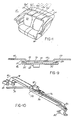
- the power tonneau cover arrangement is adapted for use with convertible automobiles of the type having a vehicle body 10 defining a passenger compartment 12 in which is mounted a rear seat 14.
- vehicle body 10 has portions defining a storage space 16 having areas thereof immediately to the rear of the back panel 40 and also regions along either side thereof to accommodate the convertible top frame members and covering (not shown).
- the tonneau cover arrangement 18 includes a tonneau panel assembly 20 configured to cover the storage space 16 in the region immediately to the rear of the back panel 40 and also alongside the seat 14 as indicated.
- the tonneau panel assembly 20 is mounted to the upper edge 22 of the back panel 40 so as to extend at a fixed angle, be cantilevered, normally extending to the rear over the storage space 16.
- the tonneau panel assembly 20 in this version includes a pair of rigid movable side panels 24 mounted to be movable laterally in and out, towards and away from a fixed main tonneau panel 26 with each of the side panels 24 carrying a lap panel 28 to accommodate the in and out movement without exposing a gap throughout the range of in and out motion of the side panels 24.
- Each of the side panels 24, main panel 26, and the lap panels 28 include lip portions as shown in Figure 1 extending downwardly over the adjacent portions of the body and seat 14 to provide a smooth aesthetically pleasing finished appearance.
- the convertible top (not shown) is adapted to be moved in and out of the storage space in which it is stored in being moved to the raised or stowed positions, upon movement of the tonneau panel assembly 20 out of position overlying the storage space 16.
- tonneau panel assembly 20 is shown in position entirely overlying the storage space 16, with the rear edge tight against weather stripping seal 32 mounted on the body 34 extending around the rear of the storage space 16.
- the side panels 24 have begun inward motion, partially exposing the storage space 16 with the lapping panels 28 narrowing the exposed section of main tonneau panel 26.
- the tonneau panel assembly 20 is rigidly fixed be cantilevered from the upper edge of the body panel 40 extending to the rear to normally overlie the storage space 16.
- the passenger seat 22 is hinge mounted such as to be able to be tilted forward as by an actuating mechanism 30 shown in Figures 5-7.
- the actuating device 30 is operated to move the passenger seat 22 body panel 40 from the generally vertical position shown in Figure 5, with the tonneau panel assembly 20 overlying the storage space 16 and the seat 22 held against fixed stops 36 mounted in the interior of storage space 16.
- This movement is shown as partially completed in Figure 6, beginning to open up the storage space 16.
- the opening movement is sufficient to fully open the storage space 16 as shown in Figure 7, so as to allow the convertible top to be moved into or out of the storage space 16 past the cantilevered tonneau panel assembly.
- the actuating device 30 thereafter returns the passenger seat 22 against the fixed stop 36.
- each of the side panels 24, the lap panels 28 and the main panel 26 are preferably formed of a light weight yet rigid construction such a a molded resin covered with a decorative surfacing material such as textured vinyl.
- the side panels 24 are shaped with an "arm" portion shaped to cover the side region of the storage space 16 alongside the passenger seat 22, with the remaining portion shaped to cover the portion of the region of the storage space 16 adjacent the side regions immediately to the rear of the passenger seat 22.
- Each of the side panels 24 is fastened to a respective lap panel 28, as by means of threaded fasteners (not shown), with the lap panel 28 positioned on the inboard side of a respective attached side panel 24.
- the passenger seat 22 includes the interior body panel 40 of formed metal, previously noted having an upper central region thereof shaped to define an enclosure 42, with mounting flanges 44 extending along the upper edge and flanges 54 on either side of the enclosure 42 as shown.
- Elongated guide member 46 is fastened to the flange 44 as by threaded fasteners (not shown) such as to be securely mounted thereto extending transversely across the passenger compartment.
- the elongated guide member 46 in turn slidably receives a pair of flange members 48 each secured to a respective side panel 24 as by threaded fasteners.
- the flange member 48 and guide track 46 are interfit as shown in Figure 9 to allow the guided in and out movement of the side panels 24 which are attached to flanges 49 of the flange member 48 as by threaded fasteners (not shown).
- the guide member 46 is formed with a lip on either lengthwise edge thereof into which is interfit lips 52 formed on either side of the respective flange member 48.
- the main panel 26 is fit over the elongated guide member 46 and mounted as by means of threaded fasteners (not shown) to the flange 56 formed on the center panel and flanges 54 adjacent the enclosure 42.
- a sheet metal member 57 is provided having ends each underlying a respective side panel 24 to support the free end of the side panel during its in and out motion.
- Drive means is provided in order to provide powered actuation of the in-and-out movement of the flange members 48 and the attached side panels 24.
- This includes a rotary drive assembly 58 mounted within the enclosure 42 and adapted to provide a rotary output, including an electric motor 60 driving a geared reducer 62 as are commercially available to provide a rotary output 64 on either end driving rotary flexible drive cables 66.
- the drive cables 66 are connected to in turn drive right angle drive units 68 each of a type commercially available, mounted on the under side of a respective guide track 46 as shown in Figure 9.
- the right angle drive 68 includes an output pinion gear 70 disposed in a space 72 created between the flange member 48 and the elongated guide member 46.
- Fastened to the under surface of the flange member 48 is an elongated rack gear 74 engaged with the pinion gear 70 such that upon rotation of the pinion gear, the flange member 48 is caused to traverse in the elongated guide member 46 to carry the side panels 24 in their in and out movement.
- the rotary drive assembly 58 also provides rotary power to allow powered actuation of the passenger seat 22 and body panel 40 through their tilting motion.
- the actuator 30 as best seen in Figure 10, includes an elongated track member 76 received within a guide member 78 each connected respectively to plate 81 affixed to interior body panel 40 and the body portion adjacent to storage space 16 by means of mounting brackets 80 and 82 respectivelyand pivoted at 84 and 86 to accommodate the tilting movement of the passenger seat 22.
- the gear reducer 62 is also provided with a rotary output 88 driving a flexible drive element 90 which in turn drives a right angle drive 92 mounted to the guide member 78 as shown in Figure 10.
- the right angle drive unit 92 includes an output pinion gear 94 in driving engagement with a rack gear 96 mounted to the elongated track member 76. Rotation of flexible drive element 90 and pinion gear 94 accordingly produces relative movement of the elongated member 76 and the guide member 78 towards or away from each other to thereby produce powered tilting movement of the interior body panel 40 and passenger seat 22 towards or away from the vertical position against the fixed stops 36 in storage space 16. Fixed stops may be spring mounted to accommodate a slight lost motion during seating.
- the interior body panel 40 has mounted thereto a spaced pair of hinge members 95 and mating hinge members 98 are mounted to the body portions adjacent the lower end of the passenger seat 22 as indicated in Figure 8, to enable the tilting motion described.
- Each of the right angle drives 68 and 92 are preferably of a self locking nature such as a worm gear drive so as to fix the position of the side panels 24 and the passenger seat 22 whenever the rotary drive is not actuated.
- a convertible top automobile is depicted incorporating the manually operated version of the present invention, in fragmentary form, including body structure 112 defining a passenger compartment 114.
- Body structure 112 defining a passenger compartment 114.
- Side by side seats 116 are provided, with a space 118 to the rear thereof where luggage or other items to be stowed may be placed.
- the passenger compartment 114 is optionally covered with a convertible top 120, which may be of conventional design, including a collapsible frame 121 including rear pillar members 123 and transverse bow members 122 having a fabric covering 124 stretched thereover.
- a convertible top 120 which may be of conventional design, including a collapsible frame 121 including rear pillar members 123 and transverse bow members 122 having a fabric covering 124 stretched thereover.
- Such convertible tops 120 are typically lowered into a U-shaped storage space 126 defined by the body structure 112 to the rear of the passenger compartment 114.
- the tonneau cover mechanism 128 in this version also includes a panel assembly including a main tonneau panel 130 configured to cover the storage space region 126c to the rear of an interior body panel 132 separating the space 118 and storage space 126.
- right and left side covers 134a and 134b each configured to cover the major portions of right and left side wells 126a and 126b respectively which form a part of the storage space 126.
- Cutouts 127 provide an opening for the rear pillars 123 of the convertible top 120 in the raised position. Cutouts 125 may also be provided to enable mounting of seat belt anchors within the side wells 126a, 126b as indicated.
- Each of the main tonneau cover 130, side covers 134a and 134b, and fixed corner covers 136a and 136b are configured to be lapped to be interfit together along the contiguous edges to provide a trim exterior appearance.
- a peripheral weather seal 144 is mounted to adjacent body structure 112 extending about the storage space 126, also acting to secure the edge of the fabric of the convertible top 120 to the body structure 112.
- Weather seal 144 is engaged by the peripheral outer edges of each of the main tonneau panel 130, side covers 134a and 134b, and fixed corner covers 136a and 136b.
- Each of the main tonneau panel 130, right side cover 134a, left side cover 134b, fixed corner covers 136a, 136b as well as interior body panel 132 are preferabley fabricated of lightweight rigid material, such as molded plastic or formed sheet metal.
- the main tonneau panel 130 and interior body panel 132 are connected together, as by being formed in one piece, or by being fixedly joined together, to create an integral angled panel structure.
- the main tonneau panel 130 is cantileveraged relative the interior body panel 132 to extend therefrom at a fixed angle, so that with the interior body panel 132 in a generally upright, vertical position, the main tonneau panel 130 extends generally horizontally to overlie storage space region 126c.
- the interior body panel 132 is hinged and either side at 146 to enable tilting forward of the integral structure formed by interior body panel 132 and main tonneau panel 131 from the vertical upright position so as to move the main tonneau panel 130 to uncover the storage space region 126c.
- Each of the side covers 134a, 134b are drivingly interconnected with the integral structure of the main tonneau panel 130 and interior body panel 132 with linkage means 148a and 148b respectively, to also produce an uncovering movement thereby upon tilting forward of the interior body panel 132.
- the side covers 134a and 134b are each mounted for pivoting motion at the forward inside corners thereof on a respective pivot pin 150a or 150b fixed to the interior side well body structure 152a, 152b, by means of support strats 154a, 154b, each pivoted on a respective pivot pin 150a, 150b, and affixed to the underface of a respective side cover 134a, 134b seen in Figure 3.
- the side covers 134a and 134b are pivoted inboard as the main tonneau cover 130 moves off the storage space 126 by operation of the respective linkage means 148a and 148b.
- a tether cable 158 is provided to limit the forward extent of such tilting motion, tether cable 158 anchored at either end to the body structure 112 and the inside of interior body panel 132.
- the cable 150 is drawn taut at the forwardmost extent of tilt of interior body panel 132.
- the linkage means 148a and 148b comprise an angled rigid arm 160 having a pivot joint connection 162 and 164 at either end with the respective side cover 134a, 134b and the interior body panel 132.
- the pivot joint 162 and 164 each allow pivoting with a limited degree of swiveling to accommodate the relative motion of the arm 160 required. This may be provided by an arm formed of a rod having bent ends 166 and 168 received in chambered bores formed in brackets 170 and 172 affixed to the side covers 134a, 134b and the interior body panel 172 respectively.
- the chamfered seats allow the slight swiveling required.
- arm 164 can be provided by a blade shaped angled member 164b carrying sockets 174, 176 at either end receiving ball pins 178, 180 respectively attached to brackets 170, 172 to enable the rotation and swiveling required.
- the sockets 174, 176 can be affixed to the brackets 170, 172, and the ball pins attached to the ends of arm 164.
- the covers 134a and 134b pivot inboard and move beneath the main tonneau panel 130 in uncovering the side wells. In so doing, a lateral interference could occur as seen in Figure 110.
- pivot pins 150a and 150b are skewed inwardly at slightly different angles a and b, ( Figure 19) so that each side cover 134a and 134b clear each other as they swing inward.
- the pivot pins 150a and 150b are also skewed front-to-rear to allow a sloping covering position (Figure 8), and an upward angle beneath the main tonneau panel 30 to afford additional clearance for movement of the top 20, past these components in being raised or lowered.
- the above recited objects of the present invention have been achieved in that highly aesthetic treatment of the tonneau cover has been afforded which allows a simplified operation in raising and lowering the convertible top between the stored and raised portions and which also provides a covering of the storage space 16 with the top in the raised and stored positions.
- the tilting motion of the passenger seat 22 and body panel 40 forward carrying the tonneau cover assembly eliminates the need to separately place the tonneau cover in position.
Landscapes
- Engineering & Computer Science (AREA)
- Mechanical Engineering (AREA)
- Vehicle Step Arrangements And Article Storage (AREA)
Priority Applications (1)
| Application Number | Priority Date | Filing Date | Title |
|---|---|---|---|
| DE8787111827T DE3774434D1 (de) | 1985-05-13 | 1987-08-14 | Fahrgastraumabdeckeinrichtung fuer ein kabriolett. |
Applications Claiming Priority (1)
| Application Number | Priority Date | Filing Date | Title |
|---|---|---|---|
| US06/720,349 US4687247A (en) | 1985-05-13 | 1985-05-13 | Powered tonneau cover for convertible automobiles |
Publications (2)
| Publication Number | Publication Date |
|---|---|
| EP0302963A1 true EP0302963A1 (fr) | 1989-02-15 |
| EP0302963B1 EP0302963B1 (fr) | 1991-11-06 |
Family
ID=24893678
Family Applications (1)
| Application Number | Title | Priority Date | Filing Date |
|---|---|---|---|
| EP87111827A Expired - Lifetime EP0302963B1 (fr) | 1985-05-13 | 1987-08-14 | Mécanisme de fermeture de compartiment passagers pour un cabriolet |
Country Status (3)
| Country | Link |
|---|---|
| US (2) | US4687247A (fr) |
| EP (1) | EP0302963B1 (fr) |
| DE (1) | DE3774434D1 (fr) |
Cited By (3)
| Publication number | Priority date | Publication date | Assignee | Title |
|---|---|---|---|---|
| DE19712967A1 (de) * | 1997-03-27 | 1998-10-01 | Bayerische Motoren Werke Ag | Deckelanordnung für den Verdeckkasten eines Cabriolets |
| DE10064362C1 (de) * | 2000-12-21 | 2002-07-04 | Cts Fahrzeug Dachsysteme Gmbh | Mehrteilige Verdeckkastenabdeckung für Personenkraftwagen |
| DE10131892A1 (de) * | 2001-07-04 | 2003-01-23 | Cts Fahrzeug Dachsysteme Gmbh | Abdeckung für einen Verdeckkasten zur Aufnahme eines verstellbaren Fahrzeugdaches |
Families Citing this family (52)
| Publication number | Priority date | Publication date | Assignee | Title |
|---|---|---|---|---|
| US4687247A (en) * | 1985-05-13 | 1987-08-18 | Muscat Peter P | Powered tonneau cover for convertible automobiles |
| DE3623468A1 (de) * | 1985-07-13 | 1987-01-22 | Nissan Motor | Kraftfahrzeug mit einer hardtop-karosserie und entfernbarem verdeck und ein verfahren zum entfernen und wiederanbringen eines hardtop-verdeckes an einem kraftfahrzeug |
| US4783113A (en) * | 1987-11-03 | 1988-11-08 | Cars & Concepts, Inc. | Vehicle convertible top boot assembly having storage compartment |
| IT215025Z2 (it) * | 1988-07-25 | 1990-07-30 | Pininfarina Ind Spa | Copertura flessibile per autoveicoli a tetto apribile provvista di elementi di copertura delle rientranze del coperchio del vano in cui la copertura viene ripiegata |
| US4890876A (en) * | 1989-01-04 | 1990-01-02 | Gaines Van G | Portable roadster cover |
| US4998766A (en) * | 1989-12-22 | 1991-03-12 | Chrysler Corporation | Convertible top boot attaching arrangement |
| US5225747A (en) * | 1992-01-06 | 1993-07-06 | Asc Incorporated | Single-button actuated self-correcting automatic convertible top |
| DE4201874C2 (de) * | 1992-01-24 | 1994-04-14 | Joerg Lienenkamp | Faltdachabdeckung |
| US5625981A (en) * | 1995-06-07 | 1997-05-06 | Asc Incorporated | Composite window assembly for an automotive vehicle |
| DE19535593A1 (de) * | 1995-09-25 | 1997-03-27 | Bayerische Motoren Werke Ag | Cabriolet mit einem Windschott |
| DE19538738C1 (de) * | 1995-10-18 | 1997-01-23 | Porsche Ag | Abdeckklappe für eine oberhalb eines Verdecklagers befindliche Durchlaßöffnung in einer Bordwand eines Fahrzeuges |
| US5921605A (en) * | 1995-11-27 | 1999-07-13 | Lear Corporation | Interlocking rear seat and package tray assembly |
| US5681069A (en) * | 1996-01-17 | 1997-10-28 | Gaylord; Mark Timothy | Device for supporting a rear bow of an automotive convertible top |
| US5860691A (en) * | 1996-03-22 | 1999-01-19 | Lund Industries, Incorporated | Apparatus for covering a vehicle cargo area |
| DE19618209B4 (de) * | 1996-05-07 | 2005-04-07 | Edscha Cabrio-Dachsysteme Gmbh | Verdeckkasten für Cabriolet-Fahrzeuge |
| US5988728A (en) * | 1996-05-07 | 1999-11-23 | Lund Industries, Incorporated | Tonneau cover; methods of installation and use of tonneau cover; and truck including a tonneau cover |
| USD391547S (en) | 1996-08-29 | 1998-03-03 | Dr. Ing. H.C.F. Porsche | Rear cap for a motor vehicle |
| USD399817S (en) | 1996-11-01 | 1998-10-20 | Lund Industries, Incorporated | Pickup truck cab extending tonneau cover |
| US5971469A (en) * | 1996-11-01 | 1999-10-26 | Lund Industries, Incorporated | Pickup truck cab extending tonneau cover |
| US5984400A (en) * | 1997-10-28 | 1999-11-16 | Lund Industries, Inc. | System for covering the bed and box of a pick-up truck, wagon or trailer |
| DE29802871U1 (de) * | 1998-02-19 | 1999-06-17 | Edscha Cabrio-Verdecksysteme GmbH & Co., 94491 Hengersberg | Abdeckung für Verdeckkästen von Cabriofahrzeugen |
| DE29812165U1 (de) * | 1998-07-08 | 1999-05-06 | Wilhelm Karmann GmbH, 49084 Osnabrück | Cabriolet-Fahrzeug mit einem Verdeckkasten |
| EP1038710B1 (fr) | 1999-03-26 | 2003-05-21 | CTS Fahrzeug-Dachsysteme GmbH | Capote articulée pour véhicule |
| US6217104B1 (en) | 1999-06-16 | 2001-04-17 | Cts Fahrzeug Dachsysteme Gmbh | Retractable hard top module |
| JP4292354B2 (ja) * | 1999-10-19 | 2009-07-08 | アイシン精機株式会社 | 車両用パッケージトレイ |
| DE19956882B4 (de) * | 1999-11-26 | 2004-08-19 | Cts Fahrzeug-Dachsysteme Gmbh | Verstellbare Klappe in der Verkleidung eines Fahrzeugs |
| DE10036223B4 (de) | 2000-07-26 | 2004-07-29 | Cts Fahrzeug-Dachsysteme Gmbh | Mehrteilige Abdeckung für den Aufnahmeraum eines Verdeckes |
| US6254165B1 (en) | 2000-08-16 | 2001-07-03 | Cts Fahrzeug Dachsysteme Gmbh | Tonneau cover and decklid linkage and drive system |
| DE10050286B4 (de) * | 2000-10-10 | 2004-08-05 | Cts Fahrzeug-Dachsysteme Gmbh | Mehrteilige Abdeckung für Fahrzeuge |
| DE10064364C1 (de) * | 2000-12-21 | 2002-06-20 | Cts Fahrzeug Dachsysteme Gmbh | Mehrteilige Abdeckung für Fahrzeuge |
| DE10064363C2 (de) * | 2000-12-21 | 2003-02-06 | Cts Fahrzeug Dachsysteme Gmbh | Mehrteilige Abdeckung für Fahrzeuge |
| US6508502B2 (en) * | 2001-02-08 | 2003-01-21 | Asc Incorporated | Convertible roof and tonneau cover system |
| US6595522B2 (en) * | 2001-10-11 | 2003-07-22 | Asc Incorporated | Vehicle seat covering system |
| DE10153137B4 (de) * | 2001-10-27 | 2005-03-10 | Karmann Gmbh W | Cabriolet-Fahrzeug mit einem unterhalb einer Ebene eines Deckelteils ablegbaren Dach |
| DE10157818C1 (de) * | 2001-11-27 | 2003-04-17 | Cts Fahrzeug Dachsysteme Gmbh | Abdeckanordnung für Fahrzeuge mit öffnungsfähigem Fahrzeugdach |
| DE10158058B4 (de) * | 2001-11-27 | 2013-11-28 | Volkswagen Ag | Cabriolet-Fahrzeug mit Durchtrittsöffnungen für Gestängeteile |
| DE10158400B4 (de) * | 2001-11-28 | 2016-09-08 | Valmet Automotive Oy | Cabriolet-Fahrzeug mit Durchtrittsöffnungen für Gestängeteile |
| FR2834951B1 (fr) * | 2002-01-21 | 2004-06-04 | France Design | Tablette arriere pour vehicule automobile dote d'un toit repliable |
| FR2834949B1 (fr) * | 2002-01-21 | 2004-03-12 | France Design | Tablette arriere pour vehicule automobile dote d'un toit repliable |
| FR2839282B1 (fr) * | 2002-05-03 | 2005-04-22 | France Design | Systeme de plage arriere escamotable pour vehicule decouvrable a toit repliable |
| FR2839474B1 (fr) * | 2002-05-13 | 2005-01-14 | France Design | Plage arriere de vehicule |
| US6767047B2 (en) * | 2002-08-15 | 2004-07-27 | Asc Incorporated | Convertible roof latch |
| US6837535B2 (en) * | 2002-08-15 | 2005-01-04 | Asc Incorporated | Convertible roof system |
| US6866327B2 (en) * | 2003-02-06 | 2005-03-15 | Asc Incorporated | Tonneau panel mechanism |
| FR2851509A1 (fr) * | 2003-02-21 | 2004-08-27 | Renault Sa | Dispositif de toit escamotable et vehicule equipe d'un tel dispositif |
| US7198318B2 (en) * | 2003-03-24 | 2007-04-03 | Asc Incorporated | Retractable roof structural system |
| FR2853868B1 (fr) * | 2003-04-15 | 2005-06-24 | France Design | Systeme de plage arriere escamotable pour vehicule decouvrable a toit repliable |
| DE102004027935A1 (de) * | 2004-06-08 | 2005-12-29 | Wilhelm Karmann Gmbh | Abdeckvorrichtung für eine in einem oberen Seitenwandbereich eines Cabrioletfahrzeuges angeordnete Durchtrittsöffnung |
| DE202004009799U1 (de) * | 2004-06-22 | 2004-09-09 | Wilhelm Karmann Gmbh | Abdeckvorrichtung für eine in einem oberen, hinteren Seitenwandbereich eines Cabrioletfahrzeuges angeordnete Durchgangsöffnung |
| US7347482B2 (en) * | 2004-08-31 | 2008-03-25 | Specialty Vehicle Acquisition Corp. | Tonneau cover system |
| DE102005057651B4 (de) * | 2005-12-01 | 2008-02-14 | Magna Car Top Systems Gmbh | Fahrzeug mit Abdeckanordnung |
| JP5157396B2 (ja) * | 2007-11-30 | 2013-03-06 | アイシン精機株式会社 | ルーフ収納装置 |
Citations (5)
| Publication number | Priority date | Publication date | Assignee | Title |
|---|---|---|---|---|
| US2599277A (en) * | 1948-10-25 | 1952-06-03 | Carbodies Ltd | Cover for a hood compartment of drophead motorcar bodies |
| DE931152C (de) * | 1953-07-31 | 1955-08-01 | Carbodies Ltd | Raum zur Aufnahme eines abklappbaren Kraftfahrzeugverdecks |
| US2959447A (en) * | 1958-06-30 | 1960-11-08 | Gen Motors Corp | Rear compartment cover for convertible |
| US2992042A (en) * | 1957-10-17 | 1961-07-11 | Gen Motors Corp | Vehicle closure |
| US4573732A (en) * | 1984-04-30 | 1986-03-04 | Muscat Peter P | Convertible top frame |
Family Cites Families (12)
| Publication number | Priority date | Publication date | Assignee | Title |
|---|---|---|---|---|
| DE296201C (fr) * | ||||
| DE306849C (fr) * | ||||
| DE332315C (de) * | 1918-07-11 | 1921-01-27 | Kuehlstein Wagenbau | Deckeleinrichtung fuer die Aufnahmebehaelter von an einem heb- und senkbaren Rahmen angeordneten Klappverdecken von Wagenkasten |
| DE331553C (de) * | 1919-07-05 | 1921-01-08 | Auto Verdeck Werke G M B H | Abdeckvorrichtung fuer Klappverdecke |
| US1437351A (en) * | 1921-10-27 | 1922-11-28 | Richard Emil Golde | Device for opening and closing the hoods of motor cars |
| FR816245A (fr) * | 1936-01-13 | 1937-08-03 | Daimler Benz Ag | Capote à rabattement pour voitures automobiles |
| US2117409A (en) * | 1937-03-11 | 1938-05-17 | John S Dorsey | Automobile seat |
| US3154341A (en) * | 1962-04-27 | 1964-10-27 | Wilmer T Booth | Tonneau cover |
| US3172695A (en) * | 1962-09-17 | 1965-03-09 | Ford Motor Co | Tonneau cover |
| US4687247A (en) * | 1985-05-13 | 1987-08-18 | Muscat Peter P | Powered tonneau cover for convertible automobiles |
| US4845772A (en) * | 1988-06-13 | 1989-07-04 | Motorola, Inc. | Portable radiotelephone with control switch disabling |
| JPH0773980B2 (ja) * | 1987-01-12 | 1995-08-09 | マツダ株式会社 | 車両のオ−プンル−フ構造 |
-
1985
- 1985-05-13 US US06/720,349 patent/US4687247A/en not_active Expired - Fee Related
-
1987
- 1987-08-14 US US07/085,407 patent/US4799729A/en not_active Expired - Fee Related
- 1987-08-14 DE DE8787111827T patent/DE3774434D1/de not_active Expired - Lifetime
- 1987-08-14 EP EP87111827A patent/EP0302963B1/fr not_active Expired - Lifetime
Patent Citations (5)
| Publication number | Priority date | Publication date | Assignee | Title |
|---|---|---|---|---|
| US2599277A (en) * | 1948-10-25 | 1952-06-03 | Carbodies Ltd | Cover for a hood compartment of drophead motorcar bodies |
| DE931152C (de) * | 1953-07-31 | 1955-08-01 | Carbodies Ltd | Raum zur Aufnahme eines abklappbaren Kraftfahrzeugverdecks |
| US2992042A (en) * | 1957-10-17 | 1961-07-11 | Gen Motors Corp | Vehicle closure |
| US2959447A (en) * | 1958-06-30 | 1960-11-08 | Gen Motors Corp | Rear compartment cover for convertible |
| US4573732A (en) * | 1984-04-30 | 1986-03-04 | Muscat Peter P | Convertible top frame |
Cited By (4)
| Publication number | Priority date | Publication date | Assignee | Title |
|---|---|---|---|---|
| DE19712967A1 (de) * | 1997-03-27 | 1998-10-01 | Bayerische Motoren Werke Ag | Deckelanordnung für den Verdeckkasten eines Cabriolets |
| DE10064362C1 (de) * | 2000-12-21 | 2002-07-04 | Cts Fahrzeug Dachsysteme Gmbh | Mehrteilige Verdeckkastenabdeckung für Personenkraftwagen |
| DE10131892A1 (de) * | 2001-07-04 | 2003-01-23 | Cts Fahrzeug Dachsysteme Gmbh | Abdeckung für einen Verdeckkasten zur Aufnahme eines verstellbaren Fahrzeugdaches |
| DE10131892C2 (de) * | 2001-07-04 | 2003-06-18 | Cts Fahrzeug Dachsysteme Gmbh | Abdeckung für einen Verdeckkasten zur Aufnahme eines verstellbaren Fahrzeugdaches |
Also Published As
| Publication number | Publication date |
|---|---|
| US4799729A (en) | 1989-01-24 |
| EP0302963B1 (fr) | 1991-11-06 |
| US4687247A (en) | 1987-08-18 |
| DE3774434D1 (de) | 1991-12-12 |
Similar Documents
| Publication | Publication Date | Title |
|---|---|---|
| US4799729A (en) | Tonneau cover mechanism for convertible automobiles | |
| US5785375A (en) | Retractable hard-top for an automotive vehicle | |
| US6767045B2 (en) | Lowerable motor vehicle roof for a cabriolet | |
| JP3638348B2 (ja) | コンバーチブル車輛ルーフ | |
| US4557502A (en) | Roll bar retracting mechanism for convertibles | |
| US4729592A (en) | Convertible vehicle body structure | |
| US6742829B2 (en) | Lowerable motor vehicle roof | |
| EP1038710B1 (fr) | Capote articulée pour véhicule | |
| US4830428A (en) | Sun-roof structure of a vehicle body | |
| US6629719B2 (en) | Top stack mechanism for a convertible roof | |
| JP2002103981A (ja) | コンバーチブル車の格納式ルーフ | |
| US5967591A (en) | Roof structure of an open automobile | |
| US4852935A (en) | Retractable backlight | |
| US20030080579A1 (en) | Lowerable motor vehicle roof for a cabriolet | |
| GB2311756A (en) | Convertible vehicle roof storage compartment covering arrangement | |
| WO2008014928A1 (fr) | Carrosserie de véhicule décapotable | |
| US3377099A (en) | Compartment closure for vehicle body | |
| US7354095B2 (en) | Mechanism for folding hardtop | |
| US20030052508A1 (en) | Top for a convertible vehicle | |
| JP2003507244A (ja) | 自動車の居住空間の取外し可能な被覆用モジュール及びかかるモジュールを備えた自動車 | |
| US6840564B2 (en) | Cover device for the removable roof of a convertible and a convertible with such a cover device | |
| EP1912815B1 (fr) | Voiture equipee d'un toit ouvrant | |
| US5470126A (en) | Retractable hardtop vehicle roof | |
| JPH0120087B2 (fr) | ||
| JPH0554447B2 (fr) |
Legal Events
| Date | Code | Title | Description |
|---|---|---|---|
| PUAI | Public reference made under article 153(3) epc to a published international application that has entered the european phase |
Free format text: ORIGINAL CODE: 0009012 |
|
| AK | Designated contracting states |
Kind code of ref document: A1 Designated state(s): AT BE CH DE ES FR GB GR IT LI LU NL SE |
|
| 17P | Request for examination filed |
Effective date: 19890801 |
|
| RBV | Designated contracting states (corrected) |
Designated state(s): DE FR GB IT |
|
| 17Q | First examination report despatched |
Effective date: 19900521 |
|
| GRAA | (expected) grant |
Free format text: ORIGINAL CODE: 0009210 |
|
| AK | Designated contracting states |
Kind code of ref document: B1 Designated state(s): DE FR GB IT |
|
| REF | Corresponds to: |
Ref document number: 3774434 Country of ref document: DE Date of ref document: 19911212 |
|
| ITF | It: translation for a ep patent filed | ||
| ET | Fr: translation filed | ||
| PG25 | Lapsed in a contracting state [announced via postgrant information from national office to epo] |
Ref country code: GB Effective date: 19920814 |
|
| PLBE | No opposition filed within time limit |
Free format text: ORIGINAL CODE: 0009261 |
|
| STAA | Information on the status of an ep patent application or granted ep patent |
Free format text: STATUS: NO OPPOSITION FILED WITHIN TIME LIMIT |
|
| 26N | No opposition filed | ||
| GBPC | Gb: european patent ceased through non-payment of renewal fee |
Effective date: 19920814 |
|
| PG25 | Lapsed in a contracting state [announced via postgrant information from national office to epo] |
Ref country code: FR Effective date: 19930430 |
|
| PG25 | Lapsed in a contracting state [announced via postgrant information from national office to epo] |
Ref country code: DE Effective date: 19930501 |
|
| REG | Reference to a national code |
Ref country code: FR Ref legal event code: ST |
|
| PG25 | Lapsed in a contracting state [announced via postgrant information from national office to epo] |
Ref country code: IT Free format text: LAPSE BECAUSE OF NON-PAYMENT OF DUE FEES;WARNING: LAPSES OF ITALIAN PATENTS WITH EFFECTIVE DATE BEFORE 2007 MAY HAVE OCCURRED AT ANY TIME BEFORE 2007. THE CORRECT EFFECTIVE DATE MAY BE DIFFERENT FROM THE ONE RECORDED. Effective date: 20050814 |