EP0302998A2 - Tourelle pour machine-outil - Google Patents
Tourelle pour machine-outil Download PDFInfo
- Publication number
- EP0302998A2 EP0302998A2 EP88106128A EP88106128A EP0302998A2 EP 0302998 A2 EP0302998 A2 EP 0302998A2 EP 88106128 A EP88106128 A EP 88106128A EP 88106128 A EP88106128 A EP 88106128A EP 0302998 A2 EP0302998 A2 EP 0302998A2
- Authority
- EP
- European Patent Office
- Prior art keywords
- tool
- turret
- sleeve
- axis
- rotation
- Prior art date
- Legal status (The legal status is an assumption and is not a legal conclusion. Google has not performed a legal analysis and makes no representation as to the accuracy of the status listed.)
- Granted
Links
- 230000008878 coupling Effects 0.000 claims abstract description 17
- 238000010168 coupling process Methods 0.000 claims abstract description 17
- 238000005859 coupling reaction Methods 0.000 claims abstract description 17
- 238000006073 displacement reaction Methods 0.000 claims description 6
- 230000000694 effects Effects 0.000 claims description 5
- 230000003993 interaction Effects 0.000 claims 1
- 230000002093 peripheral effect Effects 0.000 abstract description 2
- 238000003754 machining Methods 0.000 description 7
- 230000009471 action Effects 0.000 description 3
- 230000004913 activation Effects 0.000 description 1
- 230000004323 axial length Effects 0.000 description 1
- 230000008901 benefit Effects 0.000 description 1
- 238000010276 construction Methods 0.000 description 1
- 230000007812 deficiency Effects 0.000 description 1
- 230000005284 excitation Effects 0.000 description 1
- 238000000034 method Methods 0.000 description 1
- 230000008569 process Effects 0.000 description 1
- 238000005096 rolling process Methods 0.000 description 1
- 238000007789 sealing Methods 0.000 description 1
- 238000000926 separation method Methods 0.000 description 1
- 125000006850 spacer group Chemical group 0.000 description 1
Images


Classifications
-
- B—PERFORMING OPERATIONS; TRANSPORTING
- B23—MACHINE TOOLS; METAL-WORKING NOT OTHERWISE PROVIDED FOR
- B23Q—DETAILS, COMPONENTS, OR ACCESSORIES FOR MACHINE TOOLS, e.g. ARRANGEMENTS FOR COPYING OR CONTROLLING; MACHINE TOOLS IN GENERAL CHARACTERISED BY THE CONSTRUCTION OF PARTICULAR DETAILS OR COMPONENTS; COMBINATIONS OR ASSOCIATIONS OF METAL-WORKING MACHINES, NOT DIRECTED TO A PARTICULAR RESULT
- B23Q5/00—Driving or feeding mechanisms; Control arrangements therefor
- B23Q5/02—Driving main working members
- B23Q5/04—Driving main working members rotary shafts, e.g. working-spindles
-
- B—PERFORMING OPERATIONS; TRANSPORTING
- B23—MACHINE TOOLS; METAL-WORKING NOT OTHERWISE PROVIDED FOR
- B23B—TURNING; BORING
- B23B29/00—Holders for non-rotary cutting tools; Boring bars or boring heads; Accessories for tool holders
- B23B29/24—Tool holders for a plurality of cutting tools, e.g. turrets
- B23B29/32—Turrets adjustable by power drive, i.e. turret heads
- B23B29/323—Turrets with power operated angular positioning devices
-
- B—PERFORMING OPERATIONS; TRANSPORTING
- B23—MACHINE TOOLS; METAL-WORKING NOT OTHERWISE PROVIDED FOR
- B23Q—DETAILS, COMPONENTS, OR ACCESSORIES FOR MACHINE TOOLS, e.g. ARRANGEMENTS FOR COPYING OR CONTROLLING; MACHINE TOOLS IN GENERAL CHARACTERISED BY THE CONSTRUCTION OF PARTICULAR DETAILS OR COMPONENTS; COMBINATIONS OR ASSOCIATIONS OF METAL-WORKING MACHINES, NOT DIRECTED TO A PARTICULAR RESULT
- B23Q39/00—Metal-working machines incorporating a plurality of sub-assemblies, each capable of performing a metal-working operation
- B23Q39/02—Metal-working machines incorporating a plurality of sub-assemblies, each capable of performing a metal-working operation the sub-assemblies being capable of being brought to act at a single operating station
-
- B—PERFORMING OPERATIONS; TRANSPORTING
- B23—MACHINE TOOLS; METAL-WORKING NOT OTHERWISE PROVIDED FOR
- B23Q—DETAILS, COMPONENTS, OR ACCESSORIES FOR MACHINE TOOLS, e.g. ARRANGEMENTS FOR COPYING OR CONTROLLING; MACHINE TOOLS IN GENERAL CHARACTERISED BY THE CONSTRUCTION OF PARTICULAR DETAILS OR COMPONENTS; COMBINATIONS OR ASSOCIATIONS OF METAL-WORKING MACHINES, NOT DIRECTED TO A PARTICULAR RESULT
- B23Q2220/00—Machine tool components
- B23Q2220/002—Tool turrets
Definitions
- the invention relates to a tool turret for machine tools, in particular lathes or NC machining units, with a turret head which defines a turret axis and forms a rotary bearing for a tool disk which can be rotated about the turret axis and which can be indexed in rotating steps and, according to a number of tool stations, along it Has circumferentially distributed tool receptacles, in each of which tool holders provided with a holding shank can be received, of which the rotating tools provided have a drive shaft coaxial with the holding shank and rotatably mounted axially parallel to the turret axis, which can be driven by means of a drive device which can be rotated coaxially with the turret axis has mounted toothed ring with external spur toothing, which can be driven by a toothed pinion meshing with it and driven by a motor.
- a tool turret of this type is already known, cf. DE-PS 32 02 042. If there are several tool holders with rotary tools in the tool holders of the tool disk of the known turret, then the known solution all rotary tools driven in operation at the operating speed and not only the rotary tool that is located in the station, which is effective as a work station for the respective machining process.
- the idle running of the other rotary tools that are not in the work station in question means unnecessary wear of the associated bearing and gear devices and unnecessary loss of drive power.
- the running of rotary tools that are not involved in the machining process and are located outside the work station constitutes a significant safety deficiency.
- the invention is based on the object of designing a tool turret of the type mentioned in such a way that a desired rotary tool can be individually driven by a plurality of tool holders located in the tool holders of the tool disk with rotary tools.
- this object is achieved according to the invention in that the toothed ring is mounted in the turret head and is in drive connection with a sliding wheel which can be rotated in the turret head about an axis of rotation parallel to the turret axis, the position of which is selected such that the receiving shaft is one the desired tool holder can be aligned to the axis of rotation by means of a turning step of the tool disk, so that the sliding wheel can be displaced axially along its axis of rotation between a coupling position advanced against the tool disk, in which the drive shaft of the tool shaft and the sliding wheel are in clutch engagement with each other, and a retracted uncoupling position , and that a control device is provided for selectively moving the sliding wheel between the coupling position and the uncoupling position.
- the arrangement of the toothed ring in the turret itself ie the spatial separation of the toothed ring from the tool disc, it contains no gear element that is continuously driven during operation.
- the control device can be designed in such a way that the sliding wheel is automatically retracted into the uncoupling position by one turning step, depending on the process of advancing the tool disc, and is automatically pushed back into the coupling position at the end of a turning step.
- FIG. 1 shows a front view of a turret 1 of a tool turret for use in a lathe or an NC machining unit in the form of a generally cylindrical housing which can be attached, for example, to a cross support of a lathe in question or a stand or slide of a machining unit .
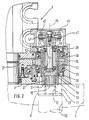
- the turret 1 has a circular front flat surface 3, on which a tool disk, not shown in FIG. 1, which is only indicated in FIG. 2 and is designated by 5, can be rotatably attached in the usual manner, the tool disk 5 being supported by a centering pin 7 is centered, which protrudes somewhat from the flat surface 3 and defines a central turret axis 8.
- the tool disk 5 is in a known manner on the turret 1 switchable in rotation steps, the number and angle of rotation are selected according to the number and position of tool stations of the tool disk 5.
- the tool stations of the tool disk 5 are tool receptacles 11 (see FIG. 2), in which tool holders with their receptacle shaft 12 can be received in such a way that the longitudinal axis of the receptacle shaft 12 in question runs axially parallel to the turret axis 8.
- the holding shank 12 shown in FIG. 2 belongs to a tool holder which is equipped with a rotary tool. This can be driven by means of a drive shaft 13 which is coaxially rotatably mounted in the receiving shaft 12, the end section 15 of which is freely accessible in the end region 17 of the tool holder 11 which faces the flat surface 3, so that the end section 15 of the drive shaft 13 in a manner to be described below with a rotary drive device is connectable.
- This drive device has, as can be seen from Fig. 1, a laterally attached to the turret 1 gear motor 19, the driven gear 20 (Fig. 1) meshes with the outer end teeth of a toothed ring 21 which is in the turret 1 at a short distance from the front Flat surface 3 is rotatably mounted about the turret axis 8.
- a toothed pinion 23 meshing with the toothed ring 21 and driven by the latter is rotatably and axially immovable in the shown embodiment in the turret head 1 at a point approximately diametrically opposite the wheel 20 in such a way that its axis of rotation 25 runs axially parallel to the turret axis 8 and to the turret axis 8 has the same radial distance as the longitudinal axes of the tool holders 11 of the tool disk 5.
- the pinion 23 has on both sides next to his
- the sliding wheel In order to transmit the rotational movement of the pinion 23, which is continuously driven during operation via the toothed ring 21, to the end section 15 of the drive shaft 13 of a tool in a tool holder 11 aligned with the axis of rotation 25, there is a sliding wheel which can be moved along the axis of rotation 25 and which can be moved with the Pinion 23 is connected to rotation.
- the sliding wheel is designed in the form of a circular cylindrical sleeve 31, the outside of which is provided with straight spline teeth 33.
- the sleeve 31 is axially displaceably mounted in the hub bore of the pinion 23, the outer spline 33 being guided in the sleeve 31 in splines 35 of the hub bore of the pinion 23, so that the sleeve 31 and pinion 23 are positively connected to rotate.
- the sleeve 31 In its front end section facing the flat surface 3, the sleeve 31 has keyways 37 on its inner wall.
- an external spline 39 on the end section 15 of the drive shaft 13 of a rotary tool arranged in the tool holder 11 comes into coupling engagement with the splines 37 in the sleeve 31.
- a control device For the optional displacement of the Sleeve 31 between the retracted decoupling position shown in FIG. 2 and the advanced coupling position in which the Spline grooves 37 of the sleeve 31 with the spline 39 on the end portion 15 of the drive shaft 13 are engaged, a control device is provided.
- this control device has an actuator designated 41 as a whole in FIG. 1, which is arranged on the outside of the turret head 1, approximately opposite the geared motor 19.
- the actuator 41 has a hydraulically actuated working cylinder 42, by means of which a shift lever 43 can be pivoted about a pivot pin 44.
- the shift lever 43 of which only the forked end 45 can be seen in FIG. 2, which serves as a shift fork, cooperates with lateral pins 47 of a control pin 49 projecting into the bore of the sleeve 31.
- the control pin 49 extends coaxially to the axis of rotation 25, but is not rotatable about the axis 25 because of the engagement between its lateral pins 47 and the ends 45 of the shift lever 43 serving as a shift fork.
- the sleeve 31 has an enlarged bore section 51 in the connection to the bore section having the keyways 37, in which two roller bearings 53 are arranged on the control mandrel 49.
- cup-shaped driver body 54 which, in cooperation with the outer ring of the associated roller bearing 53 and the inner shoulder of the sleeve 31, axially displaces the control mandrel 49 in the direction can take the tool disk 5 with it and shift it into the coupling position.
- a spacer sleeve 55 is inserted between the two roller bearings 53.
- the outer ring of the roller bearing 53 adjacent to the lateral pin 47 is in the axial direction by a retaining ring 57 fixed.
- a displacement movement of the control mandrel 49 in FIG. 2 is transmitted to the right on the sleeve 31 in order to move it into the end coupling position shown in FIG. 2.
- the actuator 41 of the control device which moves the switching lever 43 could have a different power drive instead of a hydraulic working cylinder 42, for example a control magnet or a pneumatic drive.
- the geared motor 19 with the wheel 20 driving the toothed ring 21 is arranged on one side next to the turret 1 and the toothed pinion 23, which is driven by the toothed ring 21, is located in the diametrically opposite one to the wheel 20 Side area of the turret head 1.
- the positions of the drive motor (gear motor 19) and the driven pinion 23, the axis 25 of which determines the working position of the rotary tool to be driven can be freely selected.
- the motor on the top of the turret 1 and the pinion 23 defining the working position could be arranged on the underside of the turret 1. It is also possible to provide more than one working position, for example by arranging the motor on the top or bottom of the turret 1 and by providing a pinion 23 with associated switching and control devices on each side of the motor.
- FIG. 3 which serves to explain a second exemplary embodiment of a tool turret, parts that correspond to those of the first described exemplary embodiment are denoted by reference numerals enlarged by 100 in comparison.
- This second exemplary embodiment differs from the first described exemplary embodiment mainly in that the control device for the axial displacement movements of the sleeve 131 has a different construction along the axis of rotation 125.
- the sleeve 131 is normally separated by a release spring 161 in the position shown in FIG. 3 shown uncoupled.
- the release spring 161 is supported on the one hand on the inner end of a control drum 162 and presses with its other end on a slide 163 which is displaceable on a shaft 164 which is concentric with the axis of rotation 125.
- the slider 163 has a circumferential groove 165, in which a control pin 166 engages in the wall of the sleeve 131, a limiting shoulder of the circumferential groove 165 being held in contact with the control pin 166 by the force of the release spring 161.
- the force of the release spring 161 thus acts on the control pin 166 via the slider 163 and seeks to shift it to the right (viewing direction according to FIG. 3).
- the control drum 162 is also capable of absorbing axial forces
- Rolling bearing 167 is rotatably mounted about the axis of rotation 125, but axially immovable, and is frictionally coupled to the sleeve 131, which is connected to the pinion 123 for rotation via its external spline 133.
- a sealing ring 168 which is disposed between the enlarged inner bore portion 151 of the sleeve 131 and the peripheral portion therein of the control drum 162, forms a frictional engagement which normally rotates the control drum 162 with the sleeve 131.
- the control drum 162 interacts with a magnetic brake 170, which can be activated selectively via an excitation cable 171.
- the magnetic brake 170 is able to generate a braking torque that exceeds the drag effect of the frictional engagement between the sleeve 131 and the control drum 162.
- the control pin 166 When the magnetic brake 170 is not activated, ie when the control drum 162 can be freely rotated with the sleeve 131, the control pin 166 bears against the end of the recess 172 on the right in FIG. 3 under the action of the release spring 161. If the magnetic brake 170 is now activated, the control drum 162 remains behind with respect to the rotary movement of the sleeve 131, which causes the control pin 166 in the recess 172 designed as a spiral slot or screw slot to migrate to its end 173 on the left in the drawing. This movement of the control pin 166 results in a corresponding axial displacement movement of the sleeve 131 into the advanced coupling position. If the magnetic brake 170 is deactivated again, the control pin 166 in the recess 172 moves again under the action of the spring 161 into the end position shown in FIG. 3, the sleeve 131 being moved into the uncoupling position.
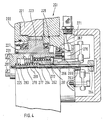
- a control drum 262 which is rotatably and axially immovably mounted with respect to the wire axis 225 by means of a roller bearing 267 and whose inner end 269 interacts with a magnetic brake 270.
- the control drum 262 also has a recess 272 in the form of a spiral or screw slot.
- the recess 272 is penetrated by a control pin 266, which is normally held in the end part of the recess 272 on the right in FIG. 4 by the force of a release spring 261.
- control pin 266 is not, however, mounted in the wall of the sleeve 231, but rather on the slider 263 slidably mounted on the shaft 264.
- the axial position of the slider 263 therefore depends on the position of the control pin 266 in the recess 272 onwards.
- Activation of the magnetic brake 270 causes the rotary movement of the control drum 262 to remain behind the sleeve 231 and the slider 263, which is connected to the sleeve 231 by means of a driving pin 277 for rotation, which is in a straight, engages axially parallel driving slot 278 of the sleeve 231.
- a driving pin 277 for rotation which is in a straight, engages axially parallel driving slot 278 of the sleeve 231.
- the driving pin 277 is located on the inner end 281 of the driving slot 278 on the right in the drawing and thereby blocks a displacement movement of the Sleeve 231 to the left in the advanced clutch position, although the sleeve 231 is biased by an engagement spring 283 for this movement in the clutch position.
- the engagement spring 283 is seated on the shaft 264 and is supported on the one hand on the slide 263 and on the other hand on the front closed end of the inner bore of the sleeve 231.
- the control pin 266 moves within the recess 272, the slide 263 being displaced to the left against the force of the release spring 261 in the drawing.
- the corresponding movement of the driving pin 277 to the left releases the sleeve 231, so that it can also move to the left into the coupling position under the action of the engagement spring 283, with outer driving lugs 287 of the sleeve 231 with associated driving members on the drive shaft of a corresponding rotary tool come into clutch engagement.
- the embodiment according to FIG. 4 is therefore the principle of a clutch for tool drives sprung by means of the engagement spring 283 in accordance with the VDMA guidelines.
Landscapes
- Engineering & Computer Science (AREA)
- Mechanical Engineering (AREA)
- Cutting Tools, Boring Holders, And Turrets (AREA)
- Automatic Tool Replacement In Machine Tools (AREA)
- Harvester Elements (AREA)
Applications Claiming Priority (2)
| Application Number | Priority Date | Filing Date | Title |
|---|---|---|---|
| DE8710865U | 1987-08-08 | ||
| DE8710865U DE8710865U1 (de) | 1987-08-08 | 1987-08-08 | Werkzeugrevolver für Werkzeugmaschinen |
Publications (3)
| Publication Number | Publication Date |
|---|---|
| EP0302998A2 true EP0302998A2 (fr) | 1989-02-15 |
| EP0302998A3 EP0302998A3 (en) | 1989-12-20 |
| EP0302998B1 EP0302998B1 (fr) | 1992-07-01 |
Family
ID=6810925
Family Applications (1)
| Application Number | Title | Priority Date | Filing Date |
|---|---|---|---|
| EP88106128A Expired - Lifetime EP0302998B1 (fr) | 1987-08-08 | 1988-04-18 | Tourelle pour machine-outil |
Country Status (3)
| Country | Link |
|---|---|
| EP (1) | EP0302998B1 (fr) |
| DE (2) | DE8710865U1 (fr) |
| ES (1) | ES2032893T3 (fr) |
Cited By (6)
| Publication number | Priority date | Publication date | Assignee | Title |
|---|---|---|---|---|
| EP0455286A3 (en) * | 1990-04-30 | 1992-06-10 | Baruffaldi S.P.A. | Coupling device for the transmission of the movement to toolholder units of automatic turrets |
| US5332344A (en) * | 1992-08-31 | 1994-07-26 | Sauter Feinmechanik Gmbh | Spindle head for tool turret |
| DE10125722A1 (de) * | 2001-05-18 | 2002-12-05 | Sauter Kg Feinmechanik | Werkzeugrevolver |
| WO2003084714A1 (fr) * | 2002-04-08 | 2003-10-16 | Duplomatic Automazione S.P.A. | Systeme d'entrainement pour outils rotatifs dans une tourelle revolver porte-outil |
| CN101829792A (zh) * | 2010-04-15 | 2010-09-15 | 沈阳机床(集团)设计研究院有限公司 | Y轴双伺服动力刀架 |
| CN117381504A (zh) * | 2023-11-16 | 2024-01-12 | 江苏美事科电机制造有限公司 | 一种数控车床非圆和偏心圆车削的进给刀架 |
Families Citing this family (1)
| Publication number | Priority date | Publication date | Assignee | Title |
|---|---|---|---|---|
| DE8710865U1 (de) * | 1987-08-08 | 1987-09-24 | Sauter Feinmechanik GmbH, 7430 Metzingen | Werkzeugrevolver für Werkzeugmaschinen |
Family Cites Families (10)
| Publication number | Priority date | Publication date | Assignee | Title |
|---|---|---|---|---|
| US2677169A (en) * | 1951-02-05 | 1954-05-04 | Stephen F Cybulski | Indexing device |
| DE1253995B (de) * | 1964-07-21 | 1967-11-09 | Magdeburg Werkzeugmasch | Elektro-hydraulische Schwenk- und Spanneinrichtung fuer einen Revolverkopf |
| JPS51126586A (en) * | 1975-04-28 | 1976-11-04 | Toyoda Mach Works Ltd | Device for stopping the spindle of turret type machining center in fix ed phase |
| DE2656608A1 (de) * | 1975-12-22 | 1977-06-30 | Smt Machine Co Ab | Werkzeugrevolver |
| DE3202042C2 (de) * | 1982-01-23 | 1987-01-22 | G. Boley GmbH & Co, Werkzeugmaschinenfabrik, 7300 Esslingen | Werkzeugrevolver für Werkzeugmaschinen, insbesondere Drehmaschinen |
| GB2126134B (en) * | 1982-09-03 | 1986-01-08 | 600 Group P L C The | Common turret indexing and tool holder drive mechanism |
| FR2539830B1 (fr) * | 1983-01-26 | 1989-03-17 | Vinel Bernard | Dispositif d'embrayage-debrayage applicable aux moyeux de roues de vehicules automobiles, en particulier les vehicules du type a quatre roues motrices ou plus |
| DE3668565D1 (de) * | 1985-08-12 | 1990-03-08 | Schaeublin Sa | Vorrichtung zum antreiben von werkzeugtraegern in einer werkzeugmaschine. |
| IT206882Z2 (it) * | 1985-09-11 | 1987-10-12 | Baruffaldi Frizioni Spa | Dispotivo per la rotazione di utensili radiali in posizioni prefissate in torrette girevoli di torni automatici. |
| DE8710865U1 (de) * | 1987-08-08 | 1987-09-24 | Sauter Feinmechanik GmbH, 7430 Metzingen | Werkzeugrevolver für Werkzeugmaschinen |
-
1987
- 1987-08-08 DE DE8710865U patent/DE8710865U1/de not_active Expired
-
1988
- 1988-04-18 ES ES198888106128T patent/ES2032893T3/es not_active Expired - Lifetime
- 1988-04-18 DE DE8888106128T patent/DE3872466D1/de not_active Expired - Lifetime
- 1988-04-18 EP EP88106128A patent/EP0302998B1/fr not_active Expired - Lifetime
Cited By (7)
| Publication number | Priority date | Publication date | Assignee | Title |
|---|---|---|---|---|
| EP0455286A3 (en) * | 1990-04-30 | 1992-06-10 | Baruffaldi S.P.A. | Coupling device for the transmission of the movement to toolholder units of automatic turrets |
| US5332344A (en) * | 1992-08-31 | 1994-07-26 | Sauter Feinmechanik Gmbh | Spindle head for tool turret |
| DE10125722A1 (de) * | 2001-05-18 | 2002-12-05 | Sauter Kg Feinmechanik | Werkzeugrevolver |
| US6722005B2 (en) | 2001-05-18 | 2004-04-20 | Sauter Feinmechanik Gmbh | Turret |
| WO2003084714A1 (fr) * | 2002-04-08 | 2003-10-16 | Duplomatic Automazione S.P.A. | Systeme d'entrainement pour outils rotatifs dans une tourelle revolver porte-outil |
| CN101829792A (zh) * | 2010-04-15 | 2010-09-15 | 沈阳机床(集团)设计研究院有限公司 | Y轴双伺服动力刀架 |
| CN117381504A (zh) * | 2023-11-16 | 2024-01-12 | 江苏美事科电机制造有限公司 | 一种数控车床非圆和偏心圆车削的进给刀架 |
Also Published As
| Publication number | Publication date |
|---|---|
| DE3872466D1 (de) | 1992-08-06 |
| ES2032893T3 (es) | 1993-03-01 |
| DE8710865U1 (de) | 1987-09-24 |
| EP0302998A3 (en) | 1989-12-20 |
| EP0302998B1 (fr) | 1992-07-01 |
Similar Documents
| Publication | Publication Date | Title |
|---|---|---|
| DE1752832C3 (de) | Vorrichtung zur lösbaren Verbindung eines Werkzeugs mit der Spindel einer Werkzeugmaschine | |
| DE3216891C2 (fr) | ||
| DE4201849C1 (fr) | ||
| DE1552227C3 (de) | Werkzeugmaschine mit einem Arbeitsmotor für Spindel- und Schlittenantrieb und einem Eilgangmotor für den Schlittenantrieb | |
| EP0415271B1 (fr) | Revolver porte-outil pour machine-outil | |
| DE7522786U (de) | Hilfsstock mit drehantreibbar umlaufender klemmeinrichtung | |
| EP0302998B1 (fr) | Tourelle pour machine-outil | |
| DE2225476A1 (de) | Manipulator | |
| DE3244019A1 (de) | Automatische handhabungsvorrichtung fuer industrielle arbeiten | |
| EP0145703B1 (fr) | Chariot transversal pour tour | |
| DE2156153B2 (fr) | ||
| DE3231782A1 (de) | Nc-gesteuerte revolver-drehmaschine | |
| DE3524879C1 (de) | Stoßfräsmaschine zum Bearbeiten der Stirnflächen der Zähne von Zahnrädern oder dgl. verzahnten Werkstücken | |
| EP0411387A1 (fr) | Engrenage à axe C | |
| DE872717C (de) | Antriebsvorrichtung fuer den Vorschub und Ruecklauf des Schlittens eines Bohr- und Fraeskopfes | |
| DE4308419A1 (de) | Werkzeugrevolver | |
| DE1294143B (de) | Durch Kraftantrieb schaltbarer Revolverkopf fuer Drehmaschinen u. dgl. | |
| DE1300417B (de) | Bohrwerk od. dgl. mit einer in der Hauptspindel verschiebbar gelagerten hohlen Bohrspindel | |
| DE3304980A1 (de) | Vorrichtung und verfahren zum herstellen und bearbeiten von zahnraedern | |
| DE685111C (de) | Revolverdrehbank | |
| DE4341142C2 (de) | Gewindeschneidapparat | |
| DE1302431B (fr) | ||
| DE2332173A1 (de) | Transfer-werkzeugmaschine mit mehreren drehbaren spannfuttern fuer die werkstuecke | |
| DE692668C (de) | Getriebe zum selbsttaetigen Umschalten von Werkzeugschlitten, insbesondere auf Drehbaenken zum Ab- und Einstecken von Eisenbahnradachsen | |
| DE731784C (de) | Vorschubgetriebe an Werkzeugmaschinen, insbesondere Senkrecht-Fraesmaschinen |
Legal Events
| Date | Code | Title | Description |
|---|---|---|---|
| PUAI | Public reference made under article 153(3) epc to a published international application that has entered the european phase |
Free format text: ORIGINAL CODE: 0009012 |
|
| AK | Designated contracting states |
Kind code of ref document: A2 Designated state(s): DE ES FR GB IT |
|
| PUAL | Search report despatched |
Free format text: ORIGINAL CODE: 0009013 |
|
| AK | Designated contracting states |
Kind code of ref document: A3 Designated state(s): DE ES FR GB IT |
|
| 17P | Request for examination filed |
Effective date: 19900309 |
|
| 17Q | First examination report despatched |
Effective date: 19910617 |
|
| ITF | It: translation for a ep patent filed | ||
| GRAA | (expected) grant |
Free format text: ORIGINAL CODE: 0009210 |
|
| STAA | Information on the status of an ep patent application or granted ep patent |
Free format text: STATUS: THE PATENT HAS BEEN GRANTED |
|
| AK | Designated contracting states |
Kind code of ref document: B1 Designated state(s): DE ES FR GB IT |
|
| ET | Fr: translation filed | ||
| GBT | Gb: translation of ep patent filed (gb section 77(6)(a)/1977) | ||
| REF | Corresponds to: |
Ref document number: 3872466 Country of ref document: DE Date of ref document: 19920806 |
|
| REG | Reference to a national code |
Ref country code: ES Ref legal event code: FG2A Ref document number: 2032893 Country of ref document: ES Kind code of ref document: T3 |
|
| PLBI | Opposition filed |
Free format text: ORIGINAL CODE: 0009260 |
|
| 26 | Opposition filed |
Opponent name: BARUFFALDI S.P.A. Effective date: 19930331 |
|
| PLBG | Opposition deemed not to have been filed |
Free format text: ORIGINAL CODE: 0009274 |
|
| 26D | Opposition deemed not to have been filed | ||
| REG | Reference to a national code |
Ref country code: GB Ref legal event code: IF02 |
|
| PGFP | Annual fee paid to national office [announced via postgrant information from national office to epo] |
Ref country code: GB Payment date: 20050316 Year of fee payment: 18 |
|
| PGFP | Annual fee paid to national office [announced via postgrant information from national office to epo] |
Ref country code: ES Payment date: 20050404 Year of fee payment: 18 |
|
| PGFP | Annual fee paid to national office [announced via postgrant information from national office to epo] |
Ref country code: FR Payment date: 20050429 Year of fee payment: 18 |
|
| PG25 | Lapsed in a contracting state [announced via postgrant information from national office to epo] |
Ref country code: GB Free format text: LAPSE BECAUSE OF NON-PAYMENT OF DUE FEES Effective date: 20060418 |
|
| PG25 | Lapsed in a contracting state [announced via postgrant information from national office to epo] |
Ref country code: ES Free format text: LAPSE BECAUSE OF NON-PAYMENT OF DUE FEES Effective date: 20060419 |
|
| GBPC | Gb: european patent ceased through non-payment of renewal fee |
Effective date: 20060418 |
|
| REG | Reference to a national code |
Ref country code: FR Ref legal event code: ST Effective date: 20061230 |
|
| PGFP | Annual fee paid to national office [announced via postgrant information from national office to epo] |
Ref country code: DE Payment date: 20070404 Year of fee payment: 20 |
|
| REG | Reference to a national code |
Ref country code: ES Ref legal event code: FD2A Effective date: 20060419 |
|
| PGFP | Annual fee paid to national office [announced via postgrant information from national office to epo] |
Ref country code: IT Payment date: 20070626 Year of fee payment: 20 |
|
| PG25 | Lapsed in a contracting state [announced via postgrant information from national office to epo] |
Ref country code: FR Free format text: LAPSE BECAUSE OF NON-PAYMENT OF DUE FEES Effective date: 20060502 |