EP0303010A1 - Etagenturm - Google Patents
Etagenturm Download PDFInfo
- Publication number
- EP0303010A1 EP0303010A1 EP88108705A EP88108705A EP0303010A1 EP 0303010 A1 EP0303010 A1 EP 0303010A1 EP 88108705 A EP88108705 A EP 88108705A EP 88108705 A EP88108705 A EP 88108705A EP 0303010 A1 EP0303010 A1 EP 0303010A1
- Authority
- EP
- European Patent Office
- Prior art keywords
- floor
- tower according
- wall
- floor tower
- double
- Prior art date
- Legal status (The legal status is an assumption and is not a legal conclusion. Google has not performed a legal analysis and makes no representation as to the accuracy of the status listed.)
- Granted
Links
- 125000006850 spacer group Chemical group 0.000 claims abstract description 18
- 238000009434 installation Methods 0.000 claims description 3
- 230000037431 insertion Effects 0.000 claims description 2
- 238000003780 insertion Methods 0.000 claims description 2
- 230000002093 peripheral effect Effects 0.000 claims 1
- 238000005516 engineering process Methods 0.000 description 2
- 239000012815 thermoplastic material Substances 0.000 description 2
- 238000004140 cleaning Methods 0.000 description 1
- 238000006073 displacement reaction Methods 0.000 description 1
- 230000002349 favourable effect Effects 0.000 description 1
- 230000005484 gravity Effects 0.000 description 1
- 238000001746 injection moulding Methods 0.000 description 1
- 238000004519 manufacturing process Methods 0.000 description 1
- 230000003287 optical effect Effects 0.000 description 1
Images


Classifications
-
- A—HUMAN NECESSITIES
- A47—FURNITURE; DOMESTIC ARTICLES OR APPLIANCES; COFFEE MILLS; SPICE MILLS; SUCTION CLEANERS IN GENERAL
- A47B—TABLES; DESKS; OFFICE FURNITURE; CABINETS; DRAWERS; GENERAL DETAILS OF FURNITURE
- A47B87/00—Sectional furniture, i.e. combinations of complete furniture units, e.g. assemblies of furniture units of the same kind such as linkable cabinets, tables, racks or shelf units
- A47B87/02—Sectional furniture, i.e. combinations of complete furniture units, e.g. assemblies of furniture units of the same kind such as linkable cabinets, tables, racks or shelf units stackable ; stackable and linkable
- A47B87/0207—Stackable racks, trays or shelf units
- A47B87/0223—Shelves stackable by means of poles or tubular members as distance-holders therebetween
Definitions
- the invention relates to a storey tower for displaying goods comprising at least two stacked shelves arranged one above the other, which are detachably connected to one another by a plurality of spacing supports, and a standing surface for installation on an essentially horizontal shelf, wherein a shelf is formed by a base plate and is surrounded by a surrounding wall arrangement .
- Such a floor tower is known for example from DE-GM 84 03 538.
- a floor is formed by a substantially horizontal plate, which is enclosed all around by the surrounding wall arrangement.
- the surrounding wall arrangement protrudes along all edges equally far above and above the horizontal of the base plate of the floor.
- the invention has for its object to develop a floor tower of the generic type in such a way that the view of the foremost exhibited goods is improved and nevertheless a safe storage of the goods on the respective storey floor is guaranteed even when the stability of the goods, for example at high Packs with a small footprint that is inherently small.
- the surrounding wall arrangement comprises a front wall of the base plate which is essentially downward along a front edge of the base plate and a rear wall which is essentially upwards directed along this area and that the base plate is supported when the standing surface is supported the stand base is inclined downwards from the front edge to the rear edge.
- the goods standing on the respective storey floor are fully visible down to their stand area.
- the inclination of the floor backwards and downwards ensures that the goods tend to tilt backwards and find a stable system on the rear wall.
- the storey floors can be stacked in a space-saving manner, since two storey floors which are placed one above the other each result in an essentially cuboid structure.
- Allowing the bottom edges of the wedge-shaped side walls to run horizontally is particularly recommended for optical reasons, but also has the technical advantage that it is possible to check that the shelves are properly constructed.
- the upper edge of a side wall when the standing surface rests on the base, runs essentially in a straight line from the level of the base plate in the area of its front edge to the upper edge of the rear wall. This ensures optimal visibility in the front area and optimal stability of the goods on display in the rear area, the latter being transferred frictionally to the front objects again.
- the standing surface be formed by the lower edges of the side walls and, if appropriate, by the lower edge of the front wall and / or the rear edge of the base plate of the lowest floor.
- the front edge can have fastening means for an advertising medium, wherein these fastening means can be designed as an upwardly open interchangeable frame for the insertion of the advertising medium.
- the shelves can have an essentially rectangular outline. In general, it is recommended - and this applies in particular to floors with a rectangular outline - that the floors are connected to each other by a total of four spacers, two of which are located near the front wall and two more near the rear wall.
- two double sockets for receiving the lower end of an upper spacer and the upper end of a lower spacer are attached to the outside of the side walls.
- the double frames each extend over the height of the side wall at the respective location of the side walls.
- the double sockets are designed as socket tubes, each of which has a central wall in the upper and lower socket bags are divided.
- the middle walls of the front and rear mounting tubes are each in a common horizontal plane when the standing surface rests on the stand floor.
- the spacer supports and the double frames are each polygonal in cross section and that a boundary wall of a double frame near the side wall lies in the associated side wall plane.
- Particularly favorable cleaning options are obtained if the spacer supports and the double frames each have an isosceles trapezoidal cross section and if two of the boundary walls of the double frames are parallel to the respective side wall, while two more diverge towards the outside of the respective side wall. Blind spots that are difficult to clean are then completely avoided.
- the double frames on one side wall and the double frames on the other side wall are offset in pairs in the longitudinal direction of the side walls are.
- Fig. 1 three floors 10 can be seen, which are connected to each other by four spacers 12 at a distance.
- the bottom floor 10 serves as a base.
- Each floor 10 comprises a base plate 14 which, as can be seen in FIG. 3, is inclined from the front and top to the back and back.
- a front wall 18 adjoins at the bottom, which is made in one piece with an interchangeable frame 20 for inserting an advertising medium.
- a rear wall 22 adjoins the rear edge 21 of the base plate 14 at the top.
- the side walls 24, 24 ' are - as can be seen from Fig. 1 - wedge-shaped with a lower edge 26 and an upper edge 28.
- the lower edge 26 lies horizontally in the erected state of the office tower and forms part of the standing area.
- the upper edge 28 runs from the front edge 16 of the base plate 14 to the upper edge 30 of the rear wall 22.
- double-socket versions 32, 34 are integrally attached, the have different heights corresponding to the height of the side walls 24 at the respective attachment point.
- the mounting tubes 32 and 34 are trapezoidal in cross-section with boundary walls 32a, 34a, 32b, 34b that are parallel to one another and boundary walls 32c, 34c, 32d, 34d that diverge from the side wall 24.
- the boundary walls 32b, 34b are parts of the side walls 24.
- the spacer supports 12 are corresponding trapezoidal hollow profiles.
- the socket tubes are divided into upper and lower socket pockets 32 I, 34 I or 32 II and 34 II by middle walls 32e, 34e.
- Each of these holder pockets receives one end of an upper or lower spacer 12. It can be seen that the middle walls 32e and 34e are at the same height. This results in different heights of the holder pockets. On the other hand, all spacer supports 12 can be of the same length, which considerably simplifies assembly.
- Fig. 5 shows that the socket tubes 32, 34 on one side wall 24 relative to the socket tubes 32 ', 34' on the other side wall 24 'are offset in pairs in the longitudinal direction of the respective side wall, so that a position of two adjacent floor towers according to Fig 5 is possible, in which their adjacent side walls 24, 24 'have a minimum distance and the front edges 16 are aligned.
- FIG. 2 shows a stiffening rib 36 on the underside 80 of the base plate 14.
- the position of this stiffening rib 36 is such that it engages both ends of one of the socket tubes 32 and 32 'despite the displacement of the socket tubes 32 and 32'.
- FIG. 2 shows node elements 38 which stiffen the front wall 18 in relation to the base plate 14.
- the rear wall 22 is stiffened by a flange 40.
- the shelves 10 can be cast or injection-molded in one piece from thermoplastic material.
- the thermoplastic material can be opaque or preferably transparent.
- stiffening ribs 36 which stiffen the base plate 14 and the front wall 18, can be provided, as shown in FIGS. 2 and 3, extending in the depth direction of the shelf.
Landscapes
- Display Racks (AREA)
- Assembled Shelves (AREA)
- Floor Finish (AREA)
Abstract
Description
- Die Erfindung betrifft einen Etagenturm zur Warenausstellung umfassend mindestens zwei übereinander angeordnete Etagenböden, welche durch eine Mehrzahl von Abstandsstützen lösbar miteinander verbunden sind, und eine Standfläche zum Aufstellen auf einen im wesentlichen horizontalen Standboden, wobei ein Etagenboden von einer Grundplatte gebildet und von einer Umfassungswandanordnung umgeben ist.
- Ein solcher Etagenturm ist beispielsweise aus dem DE-GM 84 03 538 bekannt. Dabei ist ein Etagenboden von einer im wesentlichen horizontalen Platte gebildet, welche ringsum von der Umfassungswandanordnung umschlossen ist. Die Umfassungswandanordnung steht dabei längs aller Kanten jeweils gleich weit nach oben und unten über die Horizontale der Grundplatte des Etagenbodens über.
- Der Erfindung liegt die Aufgabe zugrunde, einen Etagenturm gattungsgemäßer Art dahin weiterzubilden, daß die Sicht auf die jeweils vordersten ausgestellten Waren verbessert wird und gleichwohl eine sichere Auflagerung der Waren auf dem jeweiligen Etagenboden auch dann gewährleistet ist, wenn die Standstabilität der Waren, etwa bei hohen Packungen mit kleiner Standfläche, von Haus aus gering ist.
- Zur Lösung dieser Aufgabe wird erfindungsgemäß vorgeschlagen, daß die Umfassungswandanordnung längs einer Vorderkante der Grundplatte eine von dieser aus im wesentlichen abwärts gerichtete Vorderwand und längs einer Hinterkante der Grundplatte eine von dieser aus im wesentlichen aufwärts gerichtete Hinterwand umfaßt und daß die Grundplatte bei Auflage der Standfläche auf dem Standboden von der Vorderkante zur Hinterkante nach unter geneigt ist.
- Bei der erfindungsgemäßen Ausführungsform sind die auf dem jeweiligen Etagenboden stehenden Waren bis herab zu ihrer Standfläche voll sichtbar. Durch die Neigung des Etagenbodens nach rückwärts und unten ist sichergestellt, daß die Waren zum Kippen nach rückwärts neigen und an der Hinterwand eine stabile Anlage finden.
- Durch im wesentlichen keilförmige Seitenwände läßt sich erreichen, daß die Etagenböden raumsparend gestapelt werden können, da zwei übereinander gelegte Etagenböden zusammen jeweils ein im wesentlichen quaderförmiges Gebilde ergeben. Überdies ergibt sich eine ausreichende Seitenstabilität der ausgestellten Gegenstände zumindest im rückwärtigen Bereich, die sich durch Reibschluß unter Schwerkrafteinwirkung auch auf die jeweils vorderen Gegenstände überträgt, die dann auch von der Seite guter Einsichtmöglichkeit unterliegen.
- Die Unterkanten der keiligen Seitenwände horizontal verlaufen zu lassen, empfiehlt sich insbesondere aus optischen Gründen, hat aber auch den technischen Vorteil, daß eine Kontrolle des ordnungsgemäßen Regalaufbaus möglich ist.
- Weiter empfiehlt es sich, daß die Oberkante einer Seitenwand bei auf dem Standboden aufliegender Standfläche im wesentlichen geradlinig von dem Niveau der Grundplatte im Bereich ihrer Vorderkante zur Oberkante der 80 Hinterwand verläuft. Dadurch wird im Vorderbereich optimale Einsichtmöglichkeit und im Hinterbereich optimale Standfestigkeit der ausgestellten Ware gewährleistet, wobei sich letztere wieder reibschlüssig auf die vorderen Gegenstände überträgt.
- Um einen besonderen Standfuß einzusparen und als Stand fuß einen Etagenboden verwenden zu können, wird vorgeschlagen, daß die Standfläche von den Unterkanten der Seitenwände und gegebenenfalls von der Unterkante der Vorderwand und/oder der Hinterkante der Grundplatte des untersten Etagenbodens gebildet ist.
- Die Vorderkante kann Befestigungsmittel für einen Werbeträger aufweisen, wobei diese Befestigungsmittel als ein nach oben offener Wechselrahmen für das Einschieben des Werbeträgers ausgebildet sein können.
- Wie schon aus dem DE-GM 84 03 538 bekannt, können die Etagenböden im wesentlichen rechteckigen Umriß besitzen. Generell empfiehlt es sich - und dies gilt insbesondere für Etagenböden mit rechteckigem Umriß -, daß die Etagenböden durch insgesamt vier Abstandsstützen miteinander verbunden sind, von denen zwei in der Nähe der Vorderwand und zwei weitere in der Nähe der Hinterwand jeweils seitenwandnah angebracht sind.
- Um eine optimale Sicht von vorne zu gewährleisten, ist vorgesehen, daß an den Seitenwänden außenseitig jeweils zwei Doppelfassungen zur Aufnahme des unteren Endes einer oberen Abstandsstütze und des oberen Endes einer unteren Abstandsstütze angebracht sind.
- Im Hinblick auf ein glattes Erscheinungsbild von außen und auf gute und übersichtliche Reinigungsfähigkeit empfiehlt es sich, daß die Doppelfassungen sich jeweils über die Höhe der Seitenwand an der jeweiligen Stelle der Seitenwände erstrecken.
- Herstellungstechnisch im Hinblick auf Spritzgußtechnik ist es besonders vorteilhaft, wenn die Doppelfassungen als Fassungsröhren ausgebildet sind, welche jeweils durch eine Mittelwand in obere und untere Fassungs taschen unterteilt sind.
- Um vorne und hinten mit identischen Abstandsstützen auszukommen, wird vorgeschlagen, daß sich die Mittelwände vorderer und hinterer Fassungsröhren jeweils in einer gemeinsamen Horizontalebene befinden, wenn die Standfläche auf dem Standboden aufliegt.
- Um die Abstandsstützen bei vorgegebenem Widerstandsmoment mit möglichst geringer Ausladung gegenüber den Seitenwänden ausführen zu können, empfiehlt es sich, daß die Abstandsstützen und die Doppelfassungen im Querschnitt jeweils polygonal sind und daß jeweils eine seitenwandnahe Begrenzungswand einer Doppelfassung in der zugehörigen Seitenwandebene liegt. Besonders günstige Reinigungsmöglichkeiten ergeben sich dann, wenn die Abstandsstützen und die Doppelfassungen jeweils gleichschenklig trapezförmigen Querschnitt besitzen und wenn von den Begrenzungswänden der Doppelfassungen jeweils zwei parallel zu der jeweiligen Seitenwand sind, während zwei weitere zur Außenseite der jeweiligen Seitenwand hin divergieren. Es sind dann tote Winkel, die schwer zu reinigen sind, vollständig vermieden.
- Um aus gleichen Teilen zusammengesetzte Etagentürme mit möglichst geringem Zwischenraum nebeneinandersetzen zu können und gleichwohl eine Fluchtung der vorderkanten der Etagenböden benachbarter Etagenregale zu erhalten, ist vorgesehen, daß die Doppelfassungen an der einen Seitenwand und die Doppelfassungen an der anderen Seitenwand paarweise in Längsrichtung der Seitenwände gegeneinander versetzt sind.
- Die beiliegenden Figuren erläutern die Erfindung anhand von Ausführungsbeispielen. Es stellen dar:
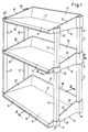
- Fig. 1 in Perspektive einen erfindungsgemäßen Etagenturm;
- Fig. 2 eine Unteransicht eines Etagenbodens in Pfeilrichtung II der Fig. 3;
- Fig. 3 einen Schnitt nach Linie III-III der Fig. 1;
- Fig. 4 einen Schnitt nach Linie IV-IV der Fig. 1 und
- Fig. 5 eine Draufsicht auf zwei benachbarte Etagenböden zweier benachbart aufgestellter Etagentürme.
- In Fig. 1 erkennt man drei Etagenböden 10, die durch jeweils vier Abstandsstützen 12 in Abstand miteinander verbunden sind. Der unterste Etagenboden 10 dient dabei als Standfuß.
- Jeder Etagenboden 10 umfaßt eine Grundplatte 14, die -wie aus Fig. 3 ersichtlich - von vorne und oben nach hinten und rückwärts geneigt ist. An der Vorderkante 16 der Grundplatte 14 schließt unten ein Vorderwand 18 an, die einstückig mit einem Wechselrahmen 20 zum Einstecken eines Werbeträgers ausgeführt ist. An die Hinterkante 21 der Grundplatte 14 schließt sich nach oben eine Hinterwand 22 an. Die Seitenwände 24, 24′ sind - wie aus Fig. 1 ersichtlich - keilig mit einer Unterkante 26 und einer Oberkante 28. Die Unterkante 26 liegt im aufgestellten Zustand des Etagenturms horizontal und bildet einen Teil der Standfläche. Die Oberkante 28 läuft von der Vorderkante 16 der Grundplatte 14 zur Oberkante 30 der Hinterwand 22.
- An den Seitenwänden 24 sind als Doppelfassungen ausgebildete Fassungsröhren 32, 34 einstückig angebracht, die unterschiedliche Höhen besitzen entsprechend der Höhe der Seitenwände 24 an der jeweiligen Anbringungsstelle. Die Fassungsröhren 32 und 34 sind - wie aus Fig. 2 ersichtlich - im Querschnitt trapezförmig mit zueinander parallelen Begrenzungswänden 32a, 34a, 32b, 34b und zur Seitenwand 24 divergierenden Begrenzungswänden 32c, 34c, 32d, 34d. Die Begrenzungswände 32b, 34b sind Teile der Seitenwände 24. Die Abstandsstützen 12 sind entsprechende trapezförmige Hohlprofile. Die Fassungsröhren sind - wie aus Fig. 4 ersichtlich - durch Mittelwände 32e, 34e in obere und untere Fassungstaschen 32 I, 34 I bzw. 32 II und 34 II unterteilt. Jede dieser Fassungstaschen nimmt ein Ende einer oberen bzw. unteren Abstandsstütze 12 auf. Man erkennt, daß die Mittelwände 32e und 34e auf gleicher Höhe liegen. Damit ergeben sich unterschiedliche Höhen der Fassungstaschen. Andererseits können sämtliche Abstandsstützen 12 gleich lang sein, was die Montage erheblich erleichtert.
- Fig. 5 läßt erkennen, daß die Fassungsröhren 32, 34 an der einen Seitenwand 24 gegenüber den Fassungsröhren 32′, 34′ an der anderen Seitenwand 24′ paarweise in Längsrichtung der jeweiligen Seitenwand zueinander versetzt sind, so daß eine Stellung zweier benachbarter Etagentürme gemäß Fig. 5 möglich ist, in der deren benachbarte Seitenwände 24, 24′ minimalen Abstand haben und die Vorderkanten 16 miteinander fluchten.
- Fig. 2 läßt eine Versteifungsrippe 36 an der Unterseite 80 der Grundplatte 14 erkennen. Die Lage dieser Versteifungsrippe 36 ist so, daß sie trotz Versetzung der Fassungsröhren 32 und 32′ mit beiden Enden jeweils an einer der Fassungsröhren 32 und 32′ angreift. Weiterhin läßt Fig. 2 Knotenelemente 38 erkennen, welche die Vorderwand 18 gegenüber der Grundplatte 14 versteifen. Die Hinterwand 22 ist durch einen Flansch 40 versteift.
- Die Etagenböden 10 können einstückig aus thermoplastischem Material gegossen oder gespritzt sein. Das thermoplastische Material kann dabei undurchsichtig oder bevorzugt transparent sein.
- Neben den bereits erwähnten Versteifungsrippen 36 können, wie in den Fig. 2 und 3 kenntlich gemacht, noch weitere in Tiefenrichtung des Regalbodens verlaufende Versteifungsrippen 80 vorgesehen sein, welche die Grundplatte 14 und die Vorderwand 18 versteifen.
Claims (20)
dadurch gekennzeichnet,
daß die Umfassungswandanordnung (18, 22, 24, 24′) längs einer Vorderkante (16) der Grundplatte (14) eine von dieser aus im wesentlichen abwärts gerichtete Vorderwand (18) und längs einer Hinterkante (21) der Grundplatte (14) eine von dieser aus im wesentlichen aufwärts gerichtete Hinterwand (22) umfaßt und daß die Grundplatte (14) bei Auflage der Standfläche auf dem Standboden von der Vorderkante (16) zur Hinterkante (21) nach unten geneigt ist.
Priority Applications (1)
| Application Number | Priority Date | Filing Date | Title |
|---|---|---|---|
| AT88108705T ATE89467T1 (de) | 1987-08-10 | 1988-05-31 | Etagenturm. |
Applications Claiming Priority (2)
| Application Number | Priority Date | Filing Date | Title |
|---|---|---|---|
| DE3726590A DE3726590C3 (de) | 1987-08-10 | 1987-08-10 | Etagenturm |
| DE3726590 | 1987-08-10 |
Publications (2)
| Publication Number | Publication Date |
|---|---|
| EP0303010A1 true EP0303010A1 (de) | 1989-02-15 |
| EP0303010B1 EP0303010B1 (de) | 1993-05-19 |
Family
ID=6333456
Family Applications (1)
| Application Number | Title | Priority Date | Filing Date |
|---|---|---|---|
| EP88108705A Expired - Lifetime EP0303010B1 (de) | 1987-08-10 | 1988-05-31 | Etagenturm |
Country Status (4)
| Country | Link |
|---|---|
| US (1) | US4901872A (de) |
| EP (1) | EP0303010B1 (de) |
| AT (1) | ATE89467T1 (de) |
| DE (3) | DE8717550U1 (de) |
Families Citing this family (58)
| Publication number | Priority date | Publication date | Assignee | Title |
|---|---|---|---|---|
| DE8905336U1 (de) * | 1989-04-27 | 1989-06-15 | Lohmann Gmbh & Co Kg, 56567 Neuwied | Vorrichtung zur Präsentation von Gegenständen |
| US4981224A (en) * | 1989-11-15 | 1991-01-01 | The Howard Marlboro Marketing, Inc. | Stacking tray display |
| US5022539A (en) * | 1990-01-05 | 1991-06-11 | Marlboro Marketing, Inc. | Two-way tray display |
| US4976360A (en) * | 1990-01-12 | 1990-12-11 | Rtc Industries, Inc. | Merchandise display stand |
| US5040690A (en) * | 1990-04-10 | 1991-08-20 | Staalkat B. V. | Rolling container |
| DE4137239A1 (de) * | 1991-11-13 | 1993-05-19 | Vkf Spork Heinz Renzel Gmbh | Faltbarer verkaufsstaender |
| US5240264A (en) * | 1992-01-27 | 1993-08-31 | Williams Thomas L | Containers on folding wheels and method |
| US5417333A (en) * | 1993-06-24 | 1995-05-23 | Paul Flum Ideas, Inc. | Gravity feed display unit with modular capability |
| US5626246A (en) * | 1995-04-13 | 1997-05-06 | Mckee Foods Corporation | Modular display rack |
| USD380324S (en) * | 1995-06-30 | 1997-07-01 | Nysco Products, Inc. | Modular display shelf |
| US6032965A (en) * | 1997-01-10 | 2000-03-07 | Pro-Mart Industries, Inc. | Stacking modular storage units with flexible containers |
| US5718343A (en) * | 1997-01-13 | 1998-02-17 | Belokin; Paul | Suspended displays |
| US6170678B1 (en) | 1997-08-15 | 2001-01-09 | Recot, Inc. | Modular display for consumer products |
| USD413745S (en) * | 1997-09-25 | 1999-09-14 | Paul Flum Ideas, Inc. | Product merchandising display unit |
| USD413217S (en) | 1997-09-25 | 1999-08-31 | Paul Flum Ideas, Inc. | Product merchandising unit |
| USD406712S (en) * | 1997-10-01 | 1999-03-16 | Paul Flum Ideas, Inc. | Product merchandising unit |
| USD407928S (en) * | 1997-10-01 | 1999-04-13 | Paul Flum Ideas, Inc. | Product merchandising unit |
| US20030080078A1 (en) * | 1998-08-13 | 2003-05-01 | Paul Belokin | Vertical display of elongated products |
| USD412078S (en) | 1998-11-06 | 1999-07-20 | Paul Flum Ideas, Inc. | Product merchandising unit |
| GB0027272D0 (en) * | 2000-11-08 | 2000-12-27 | Advanced Biotech Ltd | Storage unit |
| US20020158031A1 (en) * | 2001-04-27 | 2002-10-31 | Powers Norman C. | Kitchen lid and utensil organizer |
| USD468773S1 (en) | 2001-07-30 | 2003-01-14 | Pi-Design Ag | Paper tray |
| US20030209505A1 (en) * | 2002-05-13 | 2003-11-13 | Paul Belokin | Display shelf for stackable products |
| US20040195192A1 (en) * | 2003-04-07 | 2004-10-07 | Paul Belokin | Display assembly |
| US7051885B2 (en) * | 2003-04-07 | 2006-05-30 | Displays By Martin Paul, Inc. - Creative Center | Cross-merchandising display shelf |
| USD516359S1 (en) | 2004-03-26 | 2006-03-07 | Display By Martin Paul, Inc. - Creative Center | Display shelf with curvature |
| CN1984584B (zh) * | 2004-04-16 | 2010-04-07 | 苏珊·乔伊·拉姆齐 | 货架结构 |
| US20050274762A1 (en) * | 2004-06-14 | 2005-12-15 | Paul Belokin | Vehicle container |
| US9232864B2 (en) | 2005-09-12 | 2016-01-12 | RTC Industries, Incorporated | Product management display system with trackless pusher mechanism |
| US9138075B2 (en) | 2005-09-12 | 2015-09-22 | Rtc Industries, Inc. | Product management display system |
| US9060624B2 (en) | 2005-09-12 | 2015-06-23 | Rtc Industries, Inc. | Product management display system with rail mounting clip |
| US9173504B2 (en) | 2005-09-12 | 2015-11-03 | Rtc Industries, Inc. | Product management display system |
| US8863963B2 (en) | 2005-09-12 | 2014-10-21 | Rtc Industries, Inc. | Product management display system with trackless pusher mechanism |
| US10952546B2 (en) | 2005-09-12 | 2021-03-23 | Rtc Industries, Inc. | Product management display system with trackless pusher mechanism |
| US9265362B2 (en) | 2005-09-12 | 2016-02-23 | RTC Industries, Incorporated | Product management display system |
| US9259102B2 (en) | 2005-09-12 | 2016-02-16 | RTC Industries, Incorporated | Product management display system with trackless pusher mechanism |
| US9265358B2 (en) | 2005-09-12 | 2016-02-23 | RTC Industries, Incorporated | Product management display system |
| US8978904B2 (en) | 2005-09-12 | 2015-03-17 | Rtc Industries, Inc. | Product management display system with trackless pusher mechanism |
| US8739984B2 (en) | 2005-09-12 | 2014-06-03 | Rtc Industries, Inc. | Product management display system with trackless pusher mechanism |
| US8967394B2 (en) | 2005-09-12 | 2015-03-03 | Rtc Industries, Inc. | Product management display system with trackless pusher mechanism |
| US11583109B2 (en) | 2005-09-12 | 2023-02-21 | Rtc Industries, Inc. | Product management display system with trackless pusher mechanism |
| US10285510B2 (en) | 2005-09-12 | 2019-05-14 | Rtc Industries, Inc. | Product management display system |
| US9750354B2 (en) | 2005-09-12 | 2017-09-05 | Rtc Industries, Inc. | Product management display system |
| US11344138B2 (en) | 2005-09-12 | 2022-05-31 | Rtc Industries, Inc. | Product management display system |
| US11259652B2 (en) | 2005-09-12 | 2022-03-01 | Rtc Industries, Inc. | Product management display system |
| US9486088B2 (en) | 2005-09-12 | 2016-11-08 | Rtc Industries, Inc. | Product management display system |
| US20080000858A1 (en) * | 2006-06-30 | 2008-01-03 | Fenerty Bryan M | Modular display apparatus |
| US7762410B2 (en) * | 2006-11-30 | 2010-07-27 | Sabritas, S. De R.L. De C.V. | Modular display rack |
| US20080135698A1 (en) * | 2006-12-11 | 2008-06-12 | Tootsie Roll Industries, Inc. | Rack system |
| US20100320109A1 (en) * | 2009-06-22 | 2010-12-23 | Anthony Trumbauer | Method Of Shipping and Displaying Products For Sale To Consumers And Associated Product Display |
| US8833573B2 (en) * | 2012-01-16 | 2014-09-16 | Sonoco Development, Inc | Dividerless packaging system for shipping and displaying palletized products |
| KR101502158B1 (ko) * | 2014-10-07 | 2015-03-12 | (주) 네이처닉 | 식기건조대 |
| US9955802B2 (en) | 2015-04-08 | 2018-05-01 | Fasteners For Retail, Inc. | Divider with selectively securable track assembly |
| US11666159B2 (en) * | 2015-06-24 | 2023-06-06 | Mbm Spa | Configurable and dismantlable display case system and method of assembly |
| EP3402371B1 (de) | 2016-01-13 | 2020-03-04 | RTC Industries, Inc. | Warenauslagesystem mit einer spreizschutzvorrichtung |
| US9586803B1 (en) * | 2016-08-17 | 2017-03-07 | Tailor Made Products, Inc. | Bottle rack dispenser apparatus |
| WO2018232271A1 (en) | 2017-06-16 | 2018-12-20 | Rtc Industries, Inc. | Product management display system with trackless pusher mechanism |
| EP4228479A4 (de) * | 2020-11-18 | 2024-11-06 | Bruegmann USA, Inc. | Vertikal stapelbares, seitlich ausziehbares warenauslagesystem |
Citations (5)
| Publication number | Priority date | Publication date | Assignee | Title |
|---|---|---|---|---|
| FR2037057A1 (fr) * | 1969-01-28 | 1970-12-31 | Ferrero Gmbh | Supports pour emballages plats,en particulier boites de bonbons |
| US3704792A (en) * | 1971-06-21 | 1972-12-05 | Henschel Steinau Inc | Knock-down display |
| FR2169489A5 (de) * | 1972-01-27 | 1973-09-07 | Perfecta Maquettes | |
| EP0101647A2 (de) * | 1982-08-12 | 1984-02-29 | Walter Nathan | Geformtes Auslagetablett |
| DE8403538U1 (de) * | 1984-02-07 | 1984-07-12 | Display-Design GmbH für moderne Verkaufsförderungsmittel und Raumaussstattung, 6233 Kelkheim | Etagenturm zur warenausstellung |
Family Cites Families (15)
| Publication number | Priority date | Publication date | Assignee | Title |
|---|---|---|---|---|
| US1893755A (en) * | 1932-06-21 | 1933-01-10 | Wentworth Charles Melvin | Handy service tray assembly |
| US3346137A (en) * | 1965-04-09 | 1967-10-10 | Fausto M Ricci | Receptacle |
| US3347186A (en) * | 1966-03-24 | 1967-10-17 | Khattar Nasri | Nestable supports |
| US3970199A (en) * | 1975-01-27 | 1976-07-20 | Marschak Howard J | Display rack |
| US3964810A (en) * | 1975-05-15 | 1976-06-22 | Murphy Thomas V | Modular shelf and cabinet system |
| US3999662A (en) * | 1975-08-21 | 1976-12-28 | Barnhardt John M | Merchandise display case |
| DE2750663A1 (de) * | 1977-11-12 | 1979-06-21 | Storck August Kg | Verkaufsstaender fuer waren |
| US4711356A (en) * | 1980-10-29 | 1987-12-08 | Chef Francisco, Inc. | Container for freezing and storage of foodstuffs |
| EP0055549B1 (de) * | 1980-12-23 | 1986-03-05 | Cbm Display Group Limited | Warenschaustand |
| US4428487A (en) * | 1982-04-15 | 1984-01-31 | James Hepp | Dual side wall locking attachment for trays to vertical legs in sectional display rack |
| US4480756A (en) * | 1983-02-24 | 1984-11-06 | Belokin Jr Paul | Display rack for lightweight merchandise |
| US4706824A (en) * | 1986-03-25 | 1987-11-17 | Marlboro Marketing, Inc. | Variable sized free standing promotional display |
| US4703702A (en) * | 1986-10-16 | 1987-11-03 | Ready Metal Manufacturing Company | Multi-level pallet assembly |
| DE8628094U1 (de) * | 1986-10-22 | 1987-01-15 | ORI-PRIMAT Handelsgesellschaft mbH & Co KG, 5650 Solingen | Schauständer |
| US4763796A (en) * | 1987-03-20 | 1988-08-16 | Paul Flum Ideas, Inc. | Gravity feed display systems and conversion means for obtaining same |
-
1987
- 1987-08-10 DE DE8717550U patent/DE8717550U1/de not_active Expired
- 1987-08-10 DE DE3726590A patent/DE3726590C3/de not_active Expired - Fee Related
-
1988
- 1988-05-31 AT AT88108705T patent/ATE89467T1/de not_active IP Right Cessation
- 1988-05-31 EP EP88108705A patent/EP0303010B1/de not_active Expired - Lifetime
- 1988-05-31 DE DE8888108705T patent/DE3881117D1/de not_active Expired - Fee Related
- 1988-07-15 US US07/220,023 patent/US4901872A/en not_active Expired - Fee Related
Patent Citations (5)
| Publication number | Priority date | Publication date | Assignee | Title |
|---|---|---|---|---|
| FR2037057A1 (fr) * | 1969-01-28 | 1970-12-31 | Ferrero Gmbh | Supports pour emballages plats,en particulier boites de bonbons |
| US3704792A (en) * | 1971-06-21 | 1972-12-05 | Henschel Steinau Inc | Knock-down display |
| FR2169489A5 (de) * | 1972-01-27 | 1973-09-07 | Perfecta Maquettes | |
| EP0101647A2 (de) * | 1982-08-12 | 1984-02-29 | Walter Nathan | Geformtes Auslagetablett |
| DE8403538U1 (de) * | 1984-02-07 | 1984-07-12 | Display-Design GmbH für moderne Verkaufsförderungsmittel und Raumaussstattung, 6233 Kelkheim | Etagenturm zur warenausstellung |
Also Published As
| Publication number | Publication date |
|---|---|
| DE8717550U1 (de) | 1989-02-02 |
| US4901872A (en) | 1990-02-20 |
| DE3881117D1 (de) | 1993-06-24 |
| ATE89467T1 (de) | 1993-06-15 |
| DE3726590C2 (de) | 1990-01-25 |
| EP0303010B1 (de) | 1993-05-19 |
| DE3726590C3 (de) | 1994-07-28 |
| DE3726590A1 (de) | 1989-02-23 |
Similar Documents
| Publication | Publication Date | Title |
|---|---|---|
| EP0303010B1 (de) | Etagenturm | |
| EP0268557B1 (de) | Tablar für die Präsentierung von Waren | |
| DE2911046A1 (de) | Lagerregal mit musterwand fuer tapetenrollen o.dgl. | |
| EP1404198A1 (de) | Regalkastenartige modulelemente und display | |
| DE3436250A1 (de) | Stapelbarer lager- und transportbehaelter aus kunststoff | |
| CH677029A5 (de) | ||
| DE2620131A1 (de) | Stapel- und schachtelbarer kasten | |
| DE9013738U1 (de) | Leuchtkasten | |
| DE29510994U1 (de) | Verkaufs- und/oder Ausstellungsregal | |
| EP0009509A1 (de) | Behältnis für zum Verkauf anzubietende Waren | |
| EP0430120B1 (de) | Stapelelement | |
| DE8613621U1 (de) | Mehrstöckiges Warenregal | |
| DE3144934A1 (de) | Verkaufsstand oder regal mit auf einem sockelkasten angeordnetem aufsatz | |
| EP0118032A2 (de) | Vorrichtung zur Darstellung des Zahlenaufbaus und der Mächtigkeit von Mengen | |
| DE3540792A1 (de) | Regal | |
| DE9313255U1 (de) | Ablageschale | |
| DE9105255U1 (de) | Vorrichtung zum Aufbewahren von Disketten, Kassetten o.dgl. | |
| DE1246625B (de) | Aufbewahrungskasten, insbesondere fuer Kleinteile, Schrauben u. dgl. | |
| DE3926171A1 (de) | Verkaufsstaender | |
| DE9312891U1 (de) | Gestell | |
| DE8800041U1 (de) | Kindermöbel | |
| DE2243418A1 (de) | Vitrine zur lagerung und ausstellung von gegenstaenden | |
| DE2904897A1 (de) | Vorrichtung zum ausstellen von grusskarten, landkarten, zeitschriften, heften, buechern u.dgl. ausstellungsgegenstaenden | |
| DE7906323U1 (de) | Zusammensetzbares regal | |
| DE202004018100U1 (de) | Verbesserte Skelettkonstruktion für schachtelartige Behälter aus vorgefertigten Elementen |
Legal Events
| Date | Code | Title | Description |
|---|---|---|---|
| PUAI | Public reference made under article 153(3) epc to a published international application that has entered the european phase |
Free format text: ORIGINAL CODE: 0009012 |
|
| AK | Designated contracting states |
Kind code of ref document: A1 Designated state(s): AT BE CH DE ES FR GB GR IT LI NL SE |
|
| 17P | Request for examination filed |
Effective date: 19890804 |
|
| 17Q | First examination report despatched |
Effective date: 19901204 |
|
| GRAA | (expected) grant |
Free format text: ORIGINAL CODE: 0009210 |
|
| RAP1 | Party data changed (applicant data changed or rights of an application transferred) |
Owner name: INSTORE-MARKETING GMBH |
|
| AK | Designated contracting states |
Kind code of ref document: B1 Designated state(s): AT BE CH DE ES FR GB GR IT LI NL SE |
|
| PG25 | Lapsed in a contracting state [announced via postgrant information from national office to epo] |
Ref country code: IT Free format text: LAPSE BECAUSE OF FAILURE TO SUBMIT A TRANSLATION OF THE DESCRIPTION OR TO PAY THE FEE WITHIN THE PRE;WARNING: LAPSES OF ITALIAN PATENTS WITH EFFECTIVE DATE BEFORE 2007 MAY HAVE OCCURRED AT ANY TIME BEFORE 2007. THE CORRECT EFFECTIVE DATE MAY BE DIFFERENT FROM THE ONE RECORDED.SCRIBED TIME-LIMIT Effective date: 19930519 Ref country code: NL Effective date: 19930519 Ref country code: SE Effective date: 19930519 Ref country code: GB Effective date: 19930519 Ref country code: GR Free format text: LAPSE BECAUSE OF FAILURE TO SUBMIT A TRANSLATION OF THE DESCRIPTION OR TO PAY THE FEE WITHIN THE PRESCRIBED TIME-LIMIT Effective date: 19930519 Ref country code: BE Effective date: 19930519 Ref country code: ES Free format text: THE PATENT HAS BEEN ANNULLED BY A DECISION OF A NATIONAL AUTHORITY Effective date: 19930519 Ref country code: FR Effective date: 19930519 |
|
| REF | Corresponds to: |
Ref document number: 89467 Country of ref document: AT Date of ref document: 19930615 Kind code of ref document: T |
|
| REF | Corresponds to: |
Ref document number: 3881117 Country of ref document: DE Date of ref document: 19930624 |
|
| EN | Fr: translation not filed | ||
| NLV1 | Nl: lapsed or annulled due to failure to fulfill the requirements of art. 29p and 29m of the patents act | ||
| GBV | Gb: ep patent (uk) treated as always having been void in accordance with gb section 77(7)/1977 [no translation filed] |
Effective date: 19930519 |
|
| PLBE | No opposition filed within time limit |
Free format text: ORIGINAL CODE: 0009261 |
|
| STAA | Information on the status of an ep patent application or granted ep patent |
Free format text: STATUS: NO OPPOSITION FILED WITHIN TIME LIMIT |
|
| 26N | No opposition filed | ||
| PGFP | Annual fee paid to national office [announced via postgrant information from national office to epo] |
Ref country code: CH Payment date: 19980414 Year of fee payment: 11 |
|
| PG25 | Lapsed in a contracting state [announced via postgrant information from national office to epo] |
Ref country code: LI Free format text: LAPSE BECAUSE OF NON-PAYMENT OF DUE FEES Effective date: 19990531 Ref country code: CH Free format text: LAPSE BECAUSE OF NON-PAYMENT OF DUE FEES Effective date: 19990531 |
|
| REG | Reference to a national code |
Ref country code: CH Ref legal event code: PL |
|
| PGFP | Annual fee paid to national office [announced via postgrant information from national office to epo] |
Ref country code: DE Payment date: 20020215 Year of fee payment: 15 |
|
| PGFP | Annual fee paid to national office [announced via postgrant information from national office to epo] |
Ref country code: AT Payment date: 20020308 Year of fee payment: 15 |
|
| PG25 | Lapsed in a contracting state [announced via postgrant information from national office to epo] |
Ref country code: AT Free format text: LAPSE BECAUSE OF NON-PAYMENT OF DUE FEES Effective date: 20030531 |
|
| PG25 | Lapsed in a contracting state [announced via postgrant information from national office to epo] |
Ref country code: DE Free format text: LAPSE BECAUSE OF NON-PAYMENT OF DUE FEES Effective date: 20031202 |