EP0303213A2 - Circuit pour la régulation de vitesse d'un moteur à courant continu commuté électroniquement - Google Patents
Circuit pour la régulation de vitesse d'un moteur à courant continu commuté électroniquement Download PDFInfo
- Publication number
- EP0303213A2 EP0303213A2 EP88112860A EP88112860A EP0303213A2 EP 0303213 A2 EP0303213 A2 EP 0303213A2 EP 88112860 A EP88112860 A EP 88112860A EP 88112860 A EP88112860 A EP 88112860A EP 0303213 A2 EP0303213 A2 EP 0303213A2
- Authority
- EP
- European Patent Office
- Prior art keywords
- circuit arrangement
- speed
- motor
- voltage
- speed sensor
- Prior art date
- Legal status (The legal status is an assumption and is not a legal conclusion. Google has not performed a legal analysis and makes no representation as to the accuracy of the status listed.)
- Withdrawn
Links
Images
Classifications
-
- H—ELECTRICITY
- H02—GENERATION; CONVERSION OR DISTRIBUTION OF ELECTRIC POWER
- H02P—CONTROL OR REGULATION OF ELECTRIC MOTORS, ELECTRIC GENERATORS OR DYNAMO-ELECTRIC CONVERTERS; CONTROLLING TRANSFORMERS, REACTORS OR CHOKE COILS
- H02P6/00—Arrangements for controlling synchronous motors or other dynamo-electric motors using electronic commutation dependent on the rotor position; Electronic commutators therefor
- H02P6/06—Arrangements for speed regulation of a single motor wherein the motor speed is measured and compared with a given physical value so as to adjust the motor speed
Definitions
- the invention relates to a circuit arrangement for setting the speed of an electronically commutated direct current motor connected to a direct current source.
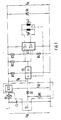
- Fig. 1 illustrates the overall circuit arrangement of an electronically commutated DC motor including an embodiment of the circuit arrangement according to the invention for speed adjustment.
- the circuit arrangement for commutating the DC motor is known in principle, for example from DE-OS 34 04 523.
- Sp1 and Sp2 denote the stator coils connected in parallel.
- the permanent magnetic rotor is indicated by the direction arrow below the stator coils.
- the dashed line between the arrow indicating the direction of rotation and the Hall IC HS is intended to illustrate that the Hall IC HS is controlled as a function of the rotational position of the permanent-magnet rotor.
- the double power operational amplifier IC1 and the resistors R1 to R4 belong to the commutation circuit.
- the Hall IC HS supplies a signal which oscillates between the positive and negative values of the direct current source U A and is fed to an input of the IC1.
- the other input of the IC1 is at half the voltage of U A via the resistor network R3, R4. The effect of this is that one output of IC1 has a positive potential and the other output has a negative potential.
- the Hall IC HS changes state, these potentials are reversed.
- Resistor R1 is a relatively low-resistance resistor which serves to protect the Hall IC HS.
- the resistor R5 is a PTC resistor, which serves to protect the stator winding and the electronic components because, when higher currents occur (e.g. when the rotor is blocked due to external influences or at impermissibly high ambient temperatures), it reduces the stator current to low values limited.
- the capacitor C1 serves to suppress interference voltages on the supply lines from the direct voltage source U B and the diode D1 suppresses brief overvoltages in the commutation circuit.
- the circuit arrangement for speed setting consists of the components which are arranged in FIG. 1 in the box formed by dash-dotted lines, namely the voltage regulator IC IC2, the diode D2 and the resistor R6.
- the input of IC2 is connected via resistor R5 to the positive electrode of the operating voltage U B , while the output of IC2 is connected to the input of the commutation circuit.
- the ground connection of the IC2 is led to the control connection St via the diode D2.
- the voltage regulator IC is arranged in the connecting line for the positive connection of U B.
- the voltage regulator IC should preferably be a act so-called "very low drop” regulator IC.
- a "negative" voltage regulator IC can also be used for the circuit arrangement for setting the speed. Such a would then be arranged in the connecting line for the negative connection of U B , and the remaining circuit arrangement for speed adjustment would then be a mirror image of the circuit arrangement shown in FIG. 1.
- the minimum permissible output voltage is set with the diode D2.
- Electronically commutated DC motors for driving fans are mainly operated with 12V and 24V. If the motor is designed for 24V, the minimum output voltage U A must be 8V. A Z diode with a breakdown voltage of 3V is then used as D2. This is the circuit arrangement as can be seen in FIG. 1.
- a minimum output voltage U A of 5.5 V is required. It is generated by reversing the polarity of the Zener diode D2 according to FIG. 1, ie operating it in the direction of flow. If the same diode is used in both cases, storage is simplified. Instead of the Z-diode operated in the direction of flow, a small-signal diode operated in the direction of flow can also be used.
- the resistor R6 serves to linearize the characteristic of the output voltage U A and to limit the maximum output voltage U A.
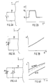
- a switch is arranged between the control input St and the negative electrode of the operating voltage U B.
- the associated speed characteristic is shown in FIG. 2b, in which the speed n is plotted against the time t.
- the control input is connected to ground. This results in a low output voltage U A , at which the motor runs at the speed n 1.
- an output voltage U A is set which corresponds to the sum of the voltage drops at R6 and D2 and the fixed voltage of IC2. At this voltage, the engine runs at n2.
- a potentiometer P which should have a positive logarithmic resistance characteristic, is connected between the control input St and ground for the continuous speed setting of the motor. If the value for R6 is selected correctly, as can be seen from FIG. 3b, there is an almost linear characteristic curve for the dependency of the engine speed n on the adjustment angle ⁇ of the potentiometer P.
- the minimum output voltage U A results from the zero ohm -Position of the potentiometer P and the maximum value for U A by the total voltage drop in the circuit of IC2, D2 and the parallel connection of P and R6.
- a PTC resistor is additionally connected in parallel to the potentiometer P already explained in connection with FIGS. 3a and 3b.
- the speed control of the motor depending on the temperature is possible.
- a family of curves with the adjustment angle ⁇ of the potentiometer P results as a parameter at the speed n as a function of the temperature T.
- the resistance-temperature characteristic of the PTC resistor has the effect that the speed of the motor also increases with increasing ambient temperature. If a pure temperature control of the engine speed is desired, the potentiometer P can also be omitted.
Landscapes
- Engineering & Computer Science (AREA)
- Power Engineering (AREA)
- Control Of Motors That Do Not Use Commutators (AREA)
- Control Of Direct Current Motors (AREA)
Applications Claiming Priority (2)
| Application Number | Priority Date | Filing Date | Title |
|---|---|---|---|
| DE19873726662 DE3726662A1 (de) | 1987-08-11 | 1987-08-11 | Schaltungsanordnung zur drehzahleinstellung eines elektronisch kommutierten gleichstrommotors |
| DE3726662 | 1987-08-11 |
Publications (2)
| Publication Number | Publication Date |
|---|---|
| EP0303213A2 true EP0303213A2 (fr) | 1989-02-15 |
| EP0303213A3 EP0303213A3 (fr) | 1989-11-29 |
Family
ID=6333500
Family Applications (1)
| Application Number | Title | Priority Date | Filing Date |
|---|---|---|---|
| EP88112860A Withdrawn EP0303213A3 (fr) | 1987-08-11 | 1988-08-06 | Circuit pour la régulation de vitesse d'un moteur à courant continu commuté électroniquement |
Country Status (2)
| Country | Link |
|---|---|
| EP (1) | EP0303213A3 (fr) |
| DE (1) | DE3726662A1 (fr) |
Cited By (1)
| Publication number | Priority date | Publication date | Assignee | Title |
|---|---|---|---|---|
| EP1338775A3 (fr) * | 2002-02-22 | 2007-03-07 | Pierburg GmbH | Commande d'un moteur à commutation électronique |
Families Citing this family (1)
| Publication number | Priority date | Publication date | Assignee | Title |
|---|---|---|---|---|
| DE3732956A1 (de) * | 1987-09-30 | 1989-04-13 | Bosch Gmbh Robert | Anordnung zum betreiben eines synchronmotors an einem gleichspannungsnetz |
Family Cites Families (14)
| Publication number | Priority date | Publication date | Assignee | Title |
|---|---|---|---|---|
| CA715192A (en) * | 1958-06-17 | 1965-08-03 | C. Shaw Chester | Regulated power supply for electric motors |
| FR1300239A (fr) * | 1961-06-20 | 1962-08-03 | Renault | Mode de réglage à action progressive de la température intérieure d'une voiture automobile |
| DE1588643A1 (de) * | 1967-03-11 | 1970-05-21 | Ritter Pfaudler Corp | Speisegeraet zur lastunabhaengigen Konstanthaltung einer beliebig vorwaehlbaren Drehzahl eines Gleichstrom-Motors mit konstantem Feld |
| DE1773796B2 (de) * | 1968-07-08 | 1971-11-25 | Farbenfabriken Bayer AG, 5090 Le verkusen | Verfahren und vorrichtung zum foerdern und dosieren von gasen fuer gasanalysen |
| DE2638615A1 (de) * | 1976-08-27 | 1978-03-02 | Bbc Brown Boveri & Cie | Drehzahlsteller fuer gleichstrommotoren |
| JPS54115750A (en) * | 1978-02-28 | 1979-09-08 | Nec Corp | Compensation circuit against source voltage characteristic |
| JPS56151830A (en) * | 1980-04-28 | 1981-11-25 | Nissan Motor Co Ltd | Blower fan speed controlling device for air conditioner |
| DE3100597A1 (de) * | 1981-01-10 | 1982-08-26 | Robert Bosch Gmbh, 7000 Stuttgart | "abgleichbare schaltungsanordnung zur stabilisierung der zwischen einem ersten leiterabschnitt und einem zweiten leiterabschnitt vorhandenen elektrischen spannung" |
| US4465958A (en) * | 1982-04-26 | 1984-08-14 | Allied Corporation | Motor speed control circuit |
| DE3340292A1 (de) * | 1982-11-09 | 1984-05-10 | Papst-Motoren GmbH & Co KG, 7742 St Georgen | Gleichstromkleinstventilator |
| DE3342031B4 (de) * | 1982-11-23 | 2005-01-13 | Papst Licensing Gmbh & Co. Kg | Schaltungsanordnung zur Drehzahlsteuerung eines Elektromotors |
| DE3404523A1 (de) * | 1984-02-09 | 1985-08-29 | Standard Elektrik Lorenz Ag, 7000 Stuttgart | Anordnung zur elektronischen kommutierung eines buerstenlosen gleichstrommotors |
| US4588933A (en) * | 1984-09-13 | 1986-05-13 | Motorola, Inc. | Brushless direct current motor control system with protection circuitry |
| US4656553A (en) * | 1986-01-21 | 1987-04-07 | Comair Rotron, Inc. | Electronically programmable universal brushless DC fan with integral tracking and locked rotor protection |
-
1987
- 1987-08-11 DE DE19873726662 patent/DE3726662A1/de not_active Withdrawn
-
1988
- 1988-08-06 EP EP88112860A patent/EP0303213A3/fr not_active Withdrawn
Cited By (1)
| Publication number | Priority date | Publication date | Assignee | Title |
|---|---|---|---|---|
| EP1338775A3 (fr) * | 2002-02-22 | 2007-03-07 | Pierburg GmbH | Commande d'un moteur à commutation électronique |
Also Published As
| Publication number | Publication date |
|---|---|
| DE3726662A1 (de) | 1989-02-23 |
| EP0303213A3 (fr) | 1989-11-29 |
Similar Documents
| Publication | Publication Date | Title |
|---|---|---|
| DE2314257C2 (de) | Schaltungsanordnung zur Drehzahlregelung eines kollektorlosen Gleichstrommotors | |
| DE69008184T2 (de) | Parametrische stromregelung für einen mikro-schritt-unipolar-motor. | |
| DE3233874C2 (fr) | ||
| DE1239390B (de) | Regelschaltung zur Konstanthaltung einer vorgegebenen Drehzahl fuer einen Gleichstrommotor mit Dauermagnetfeld | |
| DE3422368C2 (fr) | ||
| DE2658321B1 (de) | Regelanordnung fuer einen kollektorlosen Gleichstrommotor | |
| DE3715939C2 (fr) | ||
| DE4031398A1 (de) | Verfahren und schaltung zur regelung der drehgeschwindigkeit eines gleichstrommotors | |
| DE2807833A1 (de) | Buerstenloses tachometer | |
| DE2743695C2 (de) | Drehzahlregeleinrichtung für einen in der Drehrichtung umkehrbaren Gleichstrommotor mit einem Permanentmagnetrotor und einer elektronischen Kommutierungseinrichtung | |
| DE3429427C2 (fr) | ||
| DE2642472A1 (de) | Kollektorloser gleichstrommotor mit mehreren in stern geschalteten phasenwicklungen | |
| DE2461391C3 (de) | Drehzahlregelschaltung für einen kollektorlosen Gleichstrommotor | |
| DE3226549A1 (de) | Motorantrieb mit wahlweiser parallel- und serienschaltung | |
| DE3228505A1 (de) | Steueranordnung fuer einen motor | |
| EP0303213A2 (fr) | Circuit pour la régulation de vitesse d'un moteur à courant continu commuté électroniquement | |
| EP0167158A2 (fr) | Dispositif d'entraînement électrique réglé par la vitesse avec domaine d'affaiblissement de champ | |
| DE2601981A1 (de) | Kollektorloser gleichstrommotor | |
| EP1473824B1 (fr) | Unité de commande pour commander un transistor de contrôle d'un ventilateur | |
| DE2126132A1 (de) | Elektronischer Schalter zum Abbremsen von Gleichstrommotoren in Antriebssystemen für optische Apparate und Geräte | |
| DE2238627C3 (de) | Bürstenloser Gleichstrommotor | |
| DE2616044A1 (de) | Kollektorloser gleichstrommotor | |
| EP0234264B1 (fr) | Circuit de commande pour un moteur électrique pas à pas | |
| DE10020927C2 (de) | Schaltungsanordnung zur Strombegrenzung einer spannungsgesteuerten Last | |
| DE2747267A1 (de) | Schaltungsanordnung |
Legal Events
| Date | Code | Title | Description |
|---|---|---|---|
| PUAI | Public reference made under article 153(3) epc to a published international application that has entered the european phase |
Free format text: ORIGINAL CODE: 0009012 |
|
| AK | Designated contracting states |
Kind code of ref document: A2 Designated state(s): AT BE CH DE ES FR GB IT LI LU NL SE |
|
| PUAL | Search report despatched |
Free format text: ORIGINAL CODE: 0009013 |
|
| AK | Designated contracting states |
Kind code of ref document: A3 Designated state(s): AT BE CH DE ES FR GB IT LI LU NL SE |
|
| STAA | Information on the status of an ep patent application or granted ep patent |
Free format text: STATUS: THE APPLICATION IS DEEMED TO BE WITHDRAWN |
|
| 18D | Application deemed to be withdrawn |
Effective date: 19900530 |