EP0303220A2 - Pompe volumétrique à faible pulsation - Google Patents
Pompe volumétrique à faible pulsation Download PDFInfo
- Publication number
- EP0303220A2 EP0303220A2 EP88112893A EP88112893A EP0303220A2 EP 0303220 A2 EP0303220 A2 EP 0303220A2 EP 88112893 A EP88112893 A EP 88112893A EP 88112893 A EP88112893 A EP 88112893A EP 0303220 A2 EP0303220 A2 EP 0303220A2
- Authority
- EP
- European Patent Office
- Prior art keywords
- plunger
- pump
- discharge
- driving means
- plungers
- Prior art date
- Legal status (The legal status is an assumption and is not a legal conclusion. Google has not performed a legal analysis and makes no representation as to the accuracy of the status listed.)
- Granted
Links
Images



Classifications
-
- F—MECHANICAL ENGINEERING; LIGHTING; HEATING; WEAPONS; BLASTING
- F04—POSITIVE - DISPLACEMENT MACHINES FOR LIQUIDS; PUMPS FOR LIQUIDS OR ELASTIC FLUIDS
- F04B—POSITIVE-DISPLACEMENT MACHINES FOR LIQUIDS; PUMPS
- F04B11/00—Equalisation of pulses, e.g. by use of air vessels; Counteracting cavitation
-
- F—MECHANICAL ENGINEERING; LIGHTING; HEATING; WEAPONS; BLASTING
- F04—POSITIVE - DISPLACEMENT MACHINES FOR LIQUIDS; PUMPS FOR LIQUIDS OR ELASTIC FLUIDS
- F04B—POSITIVE-DISPLACEMENT MACHINES FOR LIQUIDS; PUMPS
- F04B11/00—Equalisation of pulses, e.g. by use of air vessels; Counteracting cavitation
- F04B11/005—Equalisation of pulses, e.g. by use of air vessels; Counteracting cavitation using two or more pumping pistons
- F04B11/0058—Equalisation of pulses, e.g. by use of air vessels; Counteracting cavitation using two or more pumping pistons with piston speed control
-
- F—MECHANICAL ENGINEERING; LIGHTING; HEATING; WEAPONS; BLASTING
- F04—POSITIVE - DISPLACEMENT MACHINES FOR LIQUIDS; PUMPS FOR LIQUIDS OR ELASTIC FLUIDS
- F04B—POSITIVE-DISPLACEMENT MACHINES FOR LIQUIDS; PUMPS
- F04B11/00—Equalisation of pulses, e.g. by use of air vessels; Counteracting cavitation
- F04B11/005—Equalisation of pulses, e.g. by use of air vessels; Counteracting cavitation using two or more pumping pistons
- F04B11/0075—Equalisation of pulses, e.g. by use of air vessels; Counteracting cavitation using two or more pumping pistons connected in series
- F04B11/0083—Equalisation of pulses, e.g. by use of air vessels; Counteracting cavitation using two or more pumping pistons connected in series the pistons having different cross-sections
Definitions
- This invention relates to a reciprocating fluid pump and, more particularly, to a low pulsation displacement pump having a discharge stabilizing function which is suitable for use in analyzing devices.
- the low pulsation displacement pump of the type disclosed in U.S. Patent No. 4,600,365 is structured to conduct suction and discharge in such a manner that a pair of plungers are alternately and complementarily operated by means of cams.
- the shape of the cam is specifically designed to reduce generation of pulsating flow and thereby to keep constant the composite discharge effected by operation of the two plungers.
- the accuracy of discharge depends upon the accuracy of the machined parts, such as cams and plungers. This raises a problem that the fluid discharge cannot be stabilized to a degree which exceeds the accuracy of manufactured parts.
- An object of the present invention is to provide a low pulsation displacement pump which can overcome the above-described problems and in which fluid flow variations due to manufacturing errors of the plunger and the driving means therefor can be compensated to ensure that fluids are pumped stably.
- Another object of the present invention is to provide a method of operating a low pulsation displacement pump comprising plungers and driving means therefor which method is effective to cause the pump to discharge fluids stably by restricting any variation in fluid discharge of the pump even if the plungers and the plunger driving means involve manufacturing errors.
- a further object of the present invention is to provide a low pulsation displacement pump having a structure which achieves the method.
- the method according to the present invention is to operate a pump of the type that has at least one plunger and means for reciprocating the plunger so that the liquid is sucked and discharged by the reciprocating movements of the plunger.
- the method comprises the steps of measuring errors in the amount of driving movement of the driving means at each of a plurality of predetermined operative positions of the plunger, calculating a speed correction factor of the driving means for each of the plurality of predetermined operative positions of the plunger in accordance with the thus measured errors and then storing results of the calculation in a memory, and operating the driving means while the speed of the driving means is adjusted at each of the plurality of predetermined operative positions of the plunger so that the speed of the plunger is compensated substantially to meet a designed value for thereby making the rate of discharge of the pump substantially constant.
- the pump according to the present invention is of a low pulsation displacement type and comprises at least one plunger, driving means for reciprocating the plunger, memory means which stores therein a speed correction factor of the driving means for each of a plurality of predetermined operative positions of the plunger.
- the speed correction factor has been calculated in accordance with errors in the amount of driving movement of the driving means at each of the plurality of predetermined positions of the plunger.
- the pump further includes control means for controlling the speed of the driving means in accordance with the speed correction factor.
- the controlling means is operative to actuate the driving means so that the speed of the driving means is adjusted at each of the plurality of predetermined operative positions of the plunger in accordance with the speed correction factor stored in the memory means so that the speed of the plunger is compensated substantially to a designed value and the rate of the discharge of the pump is kept substantially constant.
- the correction factor for correcting any variation in discharge due to manufacturing errors in the component parts of the plunger driving means, such as cams and plungers can be set for the pump at the manufacturing plant before delivery of the pump.
- a flow pulsation displacement pump shown in Fig. 1 is used for pumping a liquid solvent from a liquid container 21 for the purpose of passing the solvent through a fluid resistance 23 such as a separation column of a liquid chromatography.
- the low pulsation displacement pump comprises a pulse motor 1, a pair of cams 2 and 3 rotated by the motor 1, and plungers 4 and 5 which are disposed in cylinders 6 and 7 in such a manner that they can be reciprocated by the cams 2 and 3, respectively.
- An intake port of the first cylinder 6 is connected to the solvent container 21, while the outlet port of the first cylinder 6 is connected to an intake port of the second cylinder 7, and the outlet port of the second cylinder 7 is connected to the fluid resistance 23 via a pressure sensor 22.
- the intake port of the first cylinder 6 is provided with a first check value 8, while the outlet port of the cylinder 6 is provided with a second check valve 9.
- the reciprocating movement of the plungers 4 and 5 causes suction of fluid into the cylinders 6 and 7 and discharge of the fluid from these cylinders.
- the cams 2 and 3 are disposed with the phase thereof offset with each other.
- the check valves 8 and 9 are arranged to cause the fluid to flow in one direction only. Therefore, the fluid can be continuously and constantly discharged due to constant rotation of the pulse motor 1.
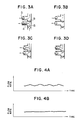
- Figs. 3A to 3D illustrate the principle of the suction and discharge of the pump.
- the two plungers 4 and 5 are successively operated, as shown in Figs. 3A, 3B, 3C and 3D, and the two check valves 8 and 9 are also successively operated as illustrated.
- the pump continuously sucks and discharges the fluid so that the fluid is continuously pumped to an aimed position.
- the cams thereof are designed in shape so as to make the speed of the plungers constant for the purpose of making fluid discharge constant.
- machining of a cam involves certain errors, which leads to a fact that the speed of the plungers cannot be made constant due to the machining error of the cams.
- the fluid discharge varies as shown in Fig. 4A. The variation is caused in synchronization with the rotation of the cams. (Principle of the compensation of fluid discharge)
- the rate of discharge f can be expressed as follows: where S is the cross sectional area of the plunger; ⁇ is the angle of rotation of the cam; and r is the radius of the cam.
- F is the rate of discharge which has been set and C(F) is constant in proportion to the rate of discharge which has been set.
- the factors (1) and (2) of the above mentioned factors form particularly major error factors.
- the error factor (1) means that the diameter of the plunger is not constant but varied at different portions thereof depending upon the location; that is, the factor (1) is a function of the angle of rotation ⁇ of the cam.
- the error factor (2) means that the slope of the cam is not constant but varied depending upon the angle; that is the factor (2) means that k is a function of the cam rotational angle ⁇ .
- K( ⁇ ) in the equation (10) needs to be made 1. This can be achieved by conducting compensation by multiplying 1/k( ⁇ ) as shown in the following equation:
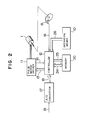
- Fig. 2 shows a control means of the pump according to the present invention.
- This control means provides a function of removing the fluid discharge variation which takes place in synchronization with the cams, and forms an essential portion of the present invention.
- an operation means 10 is a section where the rate of discharge is set and instructions for operation modes are conducted.
- a pulse motor driving means 11 receives pulse rate data 13 from a control means 12, rotates the phase of the pulse motor 1 in accordance with the pulse rate data 13, and returns a phase-rotating signal 14 to the control means 12.
- a photointerrupter 15 detects the initial position of the cams to emitt an initial position signal 16 to the control portion 12.
- An A/D converter 17 convertes a discharge pressure signal 18 from the pressure sensor 22 into a digital value 19 and sends it to the control means 12.
- a data storing means 20 is formed by a non-volatile memory, stores compensation data 24 in accordance with memory controlling data 25 from the control means 12, and feeds compensation data 24 to the control means 12.
- the control means 12 is arranged to be operative in a learning mode and an analysis mode in response to the instructions from the operation means 10.
- a predetermined value is set in step 27 shown in Fig. 5 as pulse rate for the pulse motor driving means 11.
- a value of 5 m sec is set, which is equivalent to the driving speed for a rate of discharge of 1 ml/min.
- the pulse motor 1 is rotated at a speed of 200 pps to give a rate of discharge of 1 ml/min.
- control means 12 supervises the photointerrupter 15 and waits for the cam coming to the initial position, as shown in step 28 in Fig. 5.
- the discharge pressure Pn is read (step 29 shown in Fig. 5) in every predetermined angle of rotation of the cam (every 5° in this embodiment).
- control means 12 calculates the drive pulse frequency for the pulse motor 1 in accordance with the thus set rate of discharge (step 35 shown in Fig. 6).
- Frg F X 200 pps where Frg is pulse motor drive pulse frequency and F is set rate of discharge [ml/min].
- phase rotational period T is 5/F [mS].
- this value is set in the pulse motor driving means 11 so that the pulse motor 1 is rotated while the control means 12 monitors the photointerrupter 15.
- phase rotational periods are calculated and set at every predetermined angles (in this embodiment, every 5°)
- the pulse driving means 11 rotates the pulse motor 1 by using these phase rotational periods (step 38 shown in Fig. 6).
- the learning mode is conducted only once, and the thus-stored compensation data 24 can be used until the cams or the plungers are replaced by new ones.
- the learning mode needs to be conducted only once, it can be conducted before delivery of the pump from a plant. Users are not required to conduct any learning mode of correction.
- control which needs to be conducted by users is limited to only the analysis mode.
- Fig. 7 illustrates another embodiment of the present invention.
- the plungers 4 and 5 are respectively reciprocated by feed screws 45 and 46 employed as alternatives to the cams 2 and 3 employed in the first embodiment.
- These feed screws 45 and 46 are each rotated and driven by reversible pulse motors 1 and 41.
- the directions of rotation of the motors 1 and 41 are alternatively switched with a predermined phase difference so that sliders 45a and 45b with which the feed screws 45 and 46 are threadably engaged are alternately reciprocated to drive the plungers 4 and 5 to assure a constant rate of the sum of the discharges caused by the two plungers.
- Position detectors 4 and 44 in the form of limit switches are equivalent to the photointerrupter 15 described in the above-described embodiment and are respectively disposed at one end of the reciprocating movement of respective sliders 45a and 46a.
- the position detectors 4 and 44 therefore, detect the sliders 45a and 46a reaching the one end and issue a detection signal which is used as a reference for the measurement of errors and for correction operations.
- values set for the composition of the errors of the feed screws 45 and 46 are stored in the memory so as to conduct control in such a manner that the rotational speeds of the motors 1 and 41 are compensated at every predetermined spaced positions of the feed screws whereby the rate of discharge of the pump can be made substantially constant.
- the details of this control can be easily understood by those skilled in the art from the description of the method of control in the first embodiment.
- the invention can also be applied to pumps provided with means for correcting errors due to contraction of liquids to the pumped. More specifically, liquid suffers from volume contraction due to pressure applied, although the rates of contraction very with different kinds of liquids. Thus, a pressure reduction (discharge reduction) occurs at the time of switching of a plunger suction stoke to a plunger discharge stoke. In order to prevent such a pressure reduction, a method is generally employed in which the plunger is driven at a high speed at the time of switching of the plunger strokes from the suction movement to the discharge movement.
- a method is employed in which the plungers are driven while the speeds of the plungers are compensated in accordance with correction factors throughout the overall strokes of the plungers.
- another method can be employed in which, so as to compensate for a pressure reduction, the plungers are moved at a high speed in accordance with the known compressibility of a liquid at the time of switching of the plunger strokes from the suction stroke to the discharge stroke.
- the plungers can be driven at a speed determined by the correction factor stored in the memory 20 and the set rate of discharge.
- the pump according to the present invention since the learning correction needs to be conducted only once at the manufacturing plant, users do not need to conduct it. Consequently, the pump according to the present invention can be easily used since the users do not need to prepare any dummy load for a learning correction. In addition, because it is not required to conduct measurement of errors in the rate of pump discharge during an analysis operation, the pump assures a good reproducibility of analysis data and, thus, stable analysis operations.
Landscapes
- Engineering & Computer Science (AREA)
- Mechanical Engineering (AREA)
- General Engineering & Computer Science (AREA)
- Reciprocating Pumps (AREA)
- Control Of Positive-Displacement Pumps (AREA)
Applications Claiming Priority (2)
| Application Number | Priority Date | Filing Date | Title |
|---|---|---|---|
| JP62200488A JP2824575B2 (ja) | 1987-08-11 | 1987-08-11 | 低脈流送液ポンプ |
| JP200488/87 | 1987-08-11 |
Publications (3)
| Publication Number | Publication Date |
|---|---|
| EP0303220A2 true EP0303220A2 (fr) | 1989-02-15 |
| EP0303220A3 EP0303220A3 (en) | 1990-09-05 |
| EP0303220B1 EP0303220B1 (fr) | 1993-10-27 |
Family
ID=16425150
Family Applications (1)
| Application Number | Title | Priority Date | Filing Date |
|---|---|---|---|
| EP88112893A Expired - Lifetime EP0303220B1 (fr) | 1987-08-11 | 1988-08-08 | Pompe volumétrique à faible pulsation |
Country Status (4)
| Country | Link |
|---|---|
| US (1) | US4913624A (fr) |
| EP (1) | EP0303220B1 (fr) |
| JP (1) | JP2824575B2 (fr) |
| DE (1) | DE3885193T2 (fr) |
Cited By (8)
| Publication number | Priority date | Publication date | Assignee | Title |
|---|---|---|---|---|
| DE4130295A1 (de) * | 1991-09-12 | 1993-03-25 | Ludwig Bluecher | Foerdereinrichtung |
| EP0709572A1 (fr) * | 1994-10-26 | 1996-05-01 | François Couillard | Système de pompage à pistons délivrant des fluides avec un débit sensiblement constant |
| WO1997026457A1 (fr) * | 1996-01-18 | 1997-07-24 | SEZ Semiconductor-Equipment Zubehör für die Halbleiterfertigung AG | Procede et dispositif pour doser des fluides |
| EP1236893A1 (fr) * | 2001-02-28 | 2002-09-04 | FMSW sprl | Dispositif de dosage de fluide à flux continu |
| EP1785623A1 (fr) * | 2006-10-25 | 2007-05-16 | Agilent Technologies, Inc. | Appareil de pompage avec différence de phases variable entre les pistons de pompage |
| GB2481624A (en) * | 2010-07-01 | 2012-01-04 | Agilent Technologies Inc | Controller and piezoelectric actuator provides pressure ripple compensation in chromatographic pump drive |
| WO2020112043A1 (fr) * | 2018-11-28 | 2020-06-04 | Yilmaz Ilknur | Générateur de puissance comprenant un nombre variable de cylindres à puissance et vitesse de rotation ajustables |
| EP3950107A4 (fr) * | 2019-06-12 | 2023-01-11 | Shenzhen Yhlo Biotech Co., Ltd. | Pompe de distribution de liquide et dispositif de distribution de liquide |
Families Citing this family (48)
| Publication number | Priority date | Publication date | Assignee | Title |
|---|---|---|---|---|
| US5269930A (en) * | 1990-07-13 | 1993-12-14 | Isco, Inc. | Apparatus and method for supercritical fluid extraction |
| US5635070A (en) * | 1990-07-13 | 1997-06-03 | Isco, Inc. | Apparatus and method for supercritical fluid extraction |
| US5614089A (en) | 1990-07-13 | 1997-03-25 | Isco, Inc. | Apparatus and method for supercritical fluid extraction or supercritical fluid chromatography |
| US5653885A (en) * | 1990-07-13 | 1997-08-05 | Isco, Inc. | Apparatus and method for supercritical fluid extraction |
| US5601707A (en) * | 1990-07-13 | 1997-02-11 | Isco, Inc. | Apparatus and method for supercritical fluid extraction or supercritical fluid chromatography |
| US5690828A (en) | 1990-07-13 | 1997-11-25 | Isco, Inc. | Apparatus and method for supercritical fluid extraction |
| US5250195A (en) | 1990-07-13 | 1993-10-05 | Isco, Inc. | Apparatus and method for supercritical fluid extraction |
| US5932095A (en) | 1990-07-13 | 1999-08-03 | Isco, Inc. | Multi-chambered supercritical fluid extraction cartridge |
| US5360320A (en) * | 1992-02-27 | 1994-11-01 | Isco, Inc. | Multiple solvent delivery system |
| US5253981A (en) * | 1992-03-05 | 1993-10-19 | Frank Ji-Ann Fu Yang | Multichannel pump apparatus with microflow rate capability |
| US5480288A (en) * | 1993-03-25 | 1996-01-02 | Fluid Management Limited Partnership | Pump module for dispensing apparatus |
| US5846056A (en) * | 1995-04-07 | 1998-12-08 | Dhindsa; Jasbir S. | Reciprocating pump system and method for operating same |
| US6109878A (en) * | 1998-04-13 | 2000-08-29 | Micropump, Inc. | System and a method for velocity modulation for pulseless operation of a pump |
| US8172546B2 (en) * | 1998-11-23 | 2012-05-08 | Entegris, Inc. | System and method for correcting for pressure variations using a motor |
| US6227807B1 (en) * | 1999-02-02 | 2001-05-08 | Eric Chase | Constant flow fluid pump |
| US6494685B2 (en) * | 2001-03-29 | 2002-12-17 | Kadant, Inc. | Pump and motor assembly with constant pressure output |
| US6997683B2 (en) * | 2003-01-10 | 2006-02-14 | Teledyne Isco, Inc. | High pressure reciprocating pump and control of the same |
| US20050254972A1 (en) * | 2004-05-14 | 2005-11-17 | Baker Rodney W | Bench top pump |
| US8535016B2 (en) * | 2004-07-13 | 2013-09-17 | Waters Technologies Corporation | High pressure pump control |
| US8292598B2 (en) | 2004-11-23 | 2012-10-23 | Entegris, Inc. | System and method for a variable home position dispense system |
| US8241013B2 (en) * | 2005-10-27 | 2012-08-14 | Waters Technologies Corporation | Serial capillary pump |
| US8753097B2 (en) * | 2005-11-21 | 2014-06-17 | Entegris, Inc. | Method and system for high viscosity pump |
| KR101308784B1 (ko) * | 2005-11-21 | 2013-09-17 | 엔테그리스, 아이엔씨. | 소형 폼 팩터를 갖는 펌프용 시스템 및 방법 |
| US7850431B2 (en) * | 2005-12-02 | 2010-12-14 | Entegris, Inc. | System and method for control of fluid pressure |
| KR101243509B1 (ko) | 2005-12-02 | 2013-03-20 | 엔테그리스, 아이엔씨. | 펌프에서의 압력 보상을 위한 시스템 및 방법 |
| EP1958039B9 (fr) * | 2005-12-02 | 2011-09-07 | Entegris, Inc. | Systemes d'entree/sortie, procedes et dispositifs pour assurer l'interface avec un controleur de pompe |
| US8083498B2 (en) | 2005-12-02 | 2011-12-27 | Entegris, Inc. | System and method for position control of a mechanical piston in a pump |
| US7878765B2 (en) | 2005-12-02 | 2011-02-01 | Entegris, Inc. | System and method for monitoring operation of a pump |
| US8025486B2 (en) * | 2005-12-02 | 2011-09-27 | Entegris, Inc. | System and method for valve sequencing in a pump |
| JP5345853B2 (ja) * | 2005-12-05 | 2013-11-20 | インテグリス・インコーポレーテッド | ポンプのための誤差容積システムおよび方法 |
| TWI402423B (zh) * | 2006-02-28 | 2013-07-21 | Entegris Inc | 用於一幫浦操作之系統及方法 |
| US7684446B2 (en) * | 2006-03-01 | 2010-03-23 | Entegris, Inc. | System and method for multiplexing setpoints |
| US7494265B2 (en) * | 2006-03-01 | 2009-02-24 | Entegris, Inc. | System and method for controlled mixing of fluids via temperature |
| JP4924235B2 (ja) * | 2006-08-01 | 2012-04-25 | セイコーエプソン株式会社 | 流体輸送システム、流体輸送装置 |
| KR101401849B1 (ko) * | 2006-09-26 | 2014-05-29 | 그라코 미네소타 인크. | 피스톤 펌프용 전자식 캠샤프트 모터 제어 |
| JP2009013957A (ja) * | 2007-07-09 | 2009-01-22 | Hitachi High-Technologies Corp | 送液装置とその制御方法 |
| US20090092511A1 (en) * | 2007-10-05 | 2009-04-09 | Fangfang Jiang | Heart-shaped cam constant flow pump |
| GB2474388B (en) | 2008-08-07 | 2012-11-21 | Agilent Technologies Inc | Synchronization of supply flow paths |
| DE102009020414A1 (de) * | 2009-05-08 | 2010-11-11 | Lewa Gmbh | Vergleichmäßigung des Förderstroms bei oszillierenden Verdrängerpumpen |
| US9649436B2 (en) | 2011-09-21 | 2017-05-16 | Bayer Healthcare Llc | Assembly method for a fluid pump device for a continuous multi-fluid delivery system |
| CN102913427A (zh) * | 2012-10-17 | 2013-02-06 | 常州苏控自动化设备有限公司 | 变频控制的液压泵 |
| ES3030489T3 (en) | 2015-01-09 | 2025-06-30 | Bayer Healthcare Llc | Multiple fluid delivery system with multi-use disposable set and features thereof |
| DE102015011936A1 (de) * | 2015-09-12 | 2017-03-16 | Thomas Magnete Gmbh | Vorrichtung aus mindestens zwei Hubkolbenpumpen bestehend und Verfahren zum Betrieb der Vorrichtung |
| JP6892982B2 (ja) * | 2017-02-03 | 2021-06-23 | 応研精工株式会社 | ダイヤフラムポンプ |
| TWI644819B (zh) * | 2017-11-08 | 2018-12-21 | 光陽工業股份有限公司 | Hydraulic drive unit for vehicles |
| CN109578258B (zh) * | 2018-10-12 | 2020-10-30 | 迈克医疗电子有限公司 | 液相控制方法和装置、高压恒流泵、存储介质 |
| CN112324648B (zh) * | 2020-11-02 | 2022-08-23 | 山东悟空仪器有限公司 | 串联式柱塞泵压力平衡点的控制方法及串联式柱塞泵 |
| CN120007566B (zh) * | 2025-04-22 | 2025-06-27 | 科诺美(北京)科技有限公司 | 液相泵校正方法、装置及液相泵 |
Family Cites Families (10)
| Publication number | Priority date | Publication date | Assignee | Title |
|---|---|---|---|---|
| US4137011A (en) * | 1977-06-14 | 1979-01-30 | Spectra-Physics, Inc. | Flow control system for liquid chromatographs |
| US4352636A (en) * | 1980-04-14 | 1982-10-05 | Spectra-Physics, Inc. | Dual piston pump |
| JPS5770976A (en) * | 1980-10-18 | 1982-05-01 | Nikkiso Co Ltd | Non-pulsation metering pump |
| US4772388A (en) * | 1981-09-09 | 1988-09-20 | Isco, Inc. | Apparatus for liquid chromatography |
| DE3203722C2 (de) * | 1982-02-04 | 1985-08-01 | Gynkotek Gesellschaft für den Bau wissenschaftlich-technischer Geräte mbH, 8000 München | Schubkolbenpumpe zur pulsationsarmen Förderung einer Flüssigkeit |
| CA1186166A (fr) * | 1982-02-27 | 1985-04-30 | Katsuhiko Saito | Chromatographe a liquide |
| US4507055A (en) * | 1983-07-18 | 1985-03-26 | Gulf Oil Corporation | System for automatically controlling intermittent pumping of a well |
| JPH0754114B2 (ja) * | 1985-02-01 | 1995-06-07 | 日本電子株式会社 | 送液ポンプの制御方法 |
| US4681513A (en) * | 1985-02-01 | 1987-07-21 | Jeol Ltd. | Two-stage pump assembly |
| JPH0718845B2 (ja) * | 1986-12-29 | 1995-03-06 | 横河電機株式会社 | 送液装置 |
-
1987
- 1987-08-11 JP JP62200488A patent/JP2824575B2/ja not_active Expired - Fee Related
-
1988
- 1988-08-05 US US07/228,749 patent/US4913624A/en not_active Expired - Lifetime
- 1988-08-08 EP EP88112893A patent/EP0303220B1/fr not_active Expired - Lifetime
- 1988-08-08 DE DE88112893T patent/DE3885193T2/de not_active Expired - Fee Related
Cited By (12)
| Publication number | Priority date | Publication date | Assignee | Title |
|---|---|---|---|---|
| DE4130295A1 (de) * | 1991-09-12 | 1993-03-25 | Ludwig Bluecher | Foerdereinrichtung |
| EP0709572A1 (fr) * | 1994-10-26 | 1996-05-01 | François Couillard | Système de pompage à pistons délivrant des fluides avec un débit sensiblement constant |
| FR2726332A1 (fr) * | 1994-10-26 | 1996-05-03 | Francois Couillard | Systeme de pompage a pistons delivrant des fluides avec un debit sensiblement constant |
| US5755561A (en) * | 1994-10-26 | 1998-05-26 | Francois Couillard | Piston pumping system delivering fluids with a substantially constant flow rate |
| WO1997026457A1 (fr) * | 1996-01-18 | 1997-07-24 | SEZ Semiconductor-Equipment Zubehör für die Halbleiterfertigung AG | Procede et dispositif pour doser des fluides |
| EP1236893A1 (fr) * | 2001-02-28 | 2002-09-04 | FMSW sprl | Dispositif de dosage de fluide à flux continu |
| WO2002070896A1 (fr) * | 2001-02-28 | 2002-09-12 | Cofido S.A. | Dispositif de dosage de fluide a flux continu |
| EP1785623A1 (fr) * | 2006-10-25 | 2007-05-16 | Agilent Technologies, Inc. | Appareil de pompage avec différence de phases variable entre les pistons de pompage |
| GB2481624A (en) * | 2010-07-01 | 2012-01-04 | Agilent Technologies Inc | Controller and piezoelectric actuator provides pressure ripple compensation in chromatographic pump drive |
| WO2020112043A1 (fr) * | 2018-11-28 | 2020-06-04 | Yilmaz Ilknur | Générateur de puissance comprenant un nombre variable de cylindres à puissance et vitesse de rotation ajustables |
| EP3950107A4 (fr) * | 2019-06-12 | 2023-01-11 | Shenzhen Yhlo Biotech Co., Ltd. | Pompe de distribution de liquide et dispositif de distribution de liquide |
| US12440816B2 (en) | 2019-06-12 | 2025-10-14 | Shenzhen Yhlo Biotech Co., Ltd | Liquid dispensing pump and liquid dispensing device |
Also Published As
| Publication number | Publication date |
|---|---|
| US4913624A (en) | 1990-04-03 |
| DE3885193D1 (de) | 1993-12-02 |
| DE3885193T2 (de) | 1994-04-21 |
| JPS6445982A (en) | 1989-02-20 |
| EP0303220B1 (fr) | 1993-10-27 |
| EP0303220A3 (en) | 1990-09-05 |
| JP2824575B2 (ja) | 1998-11-11 |
Similar Documents
| Publication | Publication Date | Title |
|---|---|---|
| EP0303220A2 (fr) | Pompe volumétrique à faible pulsation | |
| JP3218231B2 (ja) | ポンプ装置 | |
| US4233156A (en) | Liquid chromatography apparatus | |
| JP2586925B2 (ja) | 流体送出装置 | |
| US4808077A (en) | Pulsationless duplex plunger pump and control method thereof | |
| US7063785B2 (en) | Pump for liquid chromatography | |
| US6997683B2 (en) | High pressure reciprocating pump and control of the same | |
| EP0334994B1 (fr) | Pompe alternative délivant un fluide | |
| CA2199405C (fr) | Systeme d'amelioration de l'uniformite d'un ecoulement | |
| EP0883744B1 (fr) | Pompe | |
| EP0215525B1 (fr) | Chromatographe liquide | |
| US8871088B2 (en) | Liquid delivery device, liquid chromatograph, and method for operation of liquid delivery device | |
| GB2189555A (en) | Two-stage pump assembly | |
| AU603826B2 (en) | Liquid chromatograph | |
| CN88101279A (zh) | 泵控制系统 | |
| US4797207A (en) | Apparatus for controlling a pump to account for compressibility of liquids in obtaining steady flow | |
| JPH10501042A (ja) | 人工知能論理フィードバック制御を使用する2モード液体クロマトグラフィ | |
| US4420393A (en) | Pump for liquid chromatography and a chromatograph including the pump | |
| EP0050296B1 (fr) | Pompe volumétrique sans pulsation | |
| EP0798558A2 (fr) | Pompe à piston pour chromatographie en phase liquide à haute performance | |
| JP3117623B2 (ja) | 複数種流体混合ポンプ装置 | |
| JP4092831B2 (ja) | 送液装置 | |
| JP2559414B2 (ja) | 無脈動ポンプの制御装置 | |
| JPS61178569A (ja) | 送液ポンプの制御方法 | |
| JPS6385356A (ja) | クロマトグラフイ用送液装置 |
Legal Events
| Date | Code | Title | Description |
|---|---|---|---|
| PUAI | Public reference made under article 153(3) epc to a published international application that has entered the european phase |
Free format text: ORIGINAL CODE: 0009012 |
|
| 17P | Request for examination filed |
Effective date: 19880808 |
|
| AK | Designated contracting states |
Kind code of ref document: A2 Designated state(s): DE FR GB |
|
| PUAL | Search report despatched |
Free format text: ORIGINAL CODE: 0009013 |
|
| AK | Designated contracting states |
Kind code of ref document: A3 Designated state(s): DE FR GB |
|
| 17Q | First examination report despatched |
Effective date: 19920427 |
|
| GRAA | (expected) grant |
Free format text: ORIGINAL CODE: 0009210 |
|
| AK | Designated contracting states |
Kind code of ref document: B1 Designated state(s): DE FR GB |
|
| REF | Corresponds to: |
Ref document number: 3885193 Country of ref document: DE Date of ref document: 19931202 |
|
| ET | Fr: translation filed | ||
| PLBE | No opposition filed within time limit |
Free format text: ORIGINAL CODE: 0009261 |
|
| STAA | Information on the status of an ep patent application or granted ep patent |
Free format text: STATUS: NO OPPOSITION FILED WITHIN TIME LIMIT |
|
| 26N | No opposition filed | ||
| REG | Reference to a national code |
Ref country code: GB Ref legal event code: IF02 |
|
| PGFP | Annual fee paid to national office [announced via postgrant information from national office to epo] |
Ref country code: FR Payment date: 20060802 Year of fee payment: 19 |
|
| PGFP | Annual fee paid to national office [announced via postgrant information from national office to epo] |
Ref country code: GB Payment date: 20060808 Year of fee payment: 19 |
|
| PGFP | Annual fee paid to national office [announced via postgrant information from national office to epo] |
Ref country code: DE Payment date: 20060828 Year of fee payment: 19 |
|
| GBPC | Gb: european patent ceased through non-payment of renewal fee |
Effective date: 20070808 |
|
| REG | Reference to a national code |
Ref country code: FR Ref legal event code: ST Effective date: 20080430 |
|
| PG25 | Lapsed in a contracting state [announced via postgrant information from national office to epo] |
Ref country code: DE Free format text: LAPSE BECAUSE OF NON-PAYMENT OF DUE FEES Effective date: 20080301 |
|
| PG25 | Lapsed in a contracting state [announced via postgrant information from national office to epo] |
Ref country code: FR Free format text: LAPSE BECAUSE OF NON-PAYMENT OF DUE FEES Effective date: 20070831 |
|
| PG25 | Lapsed in a contracting state [announced via postgrant information from national office to epo] |
Ref country code: GB Free format text: LAPSE BECAUSE OF NON-PAYMENT OF DUE FEES Effective date: 20070808 |