EP0303344A1 - Dispositif d'injection de combustible - Google Patents
Dispositif d'injection de combustible Download PDFInfo
- Publication number
- EP0303344A1 EP0303344A1 EP88305880A EP88305880A EP0303344A1 EP 0303344 A1 EP0303344 A1 EP 0303344A1 EP 88305880 A EP88305880 A EP 88305880A EP 88305880 A EP88305880 A EP 88305880A EP 0303344 A1 EP0303344 A1 EP 0303344A1
- Authority
- EP
- European Patent Office
- Prior art keywords
- injection
- base
- injection tube
- fuel injection
- injection apparatus
- Prior art date
- Legal status (The legal status is an assumption and is not a legal conclusion. Google has not performed a legal analysis and makes no representation as to the accuracy of the status listed.)
- Granted
Links
- 238000002347 injection Methods 0.000 title claims abstract description 70
- 239000007924 injection Substances 0.000 title claims abstract description 70
- 239000000446 fuel Substances 0.000 title claims abstract description 32
- 230000000717 retained effect Effects 0.000 description 3
- 238000010276 construction Methods 0.000 description 2
- 230000001788 irregular Effects 0.000 description 2
- 238000002485 combustion reaction Methods 0.000 description 1
- 230000000295 complement effect Effects 0.000 description 1
- 238000007789 sealing Methods 0.000 description 1
Images
Classifications
-
- F—MECHANICAL ENGINEERING; LIGHTING; HEATING; WEAPONS; BLASTING
- F02—COMBUSTION ENGINES; HOT-GAS OR COMBUSTION-PRODUCT ENGINE PLANTS
- F02M—SUPPLYING COMBUSTION ENGINES IN GENERAL WITH COMBUSTIBLE MIXTURES OR CONSTITUENTS THEREOF
- F02M69/00—Low-pressure fuel-injection apparatus ; Apparatus with both continuous and intermittent injection; Apparatus injecting different types of fuel
- F02M69/46—Details, component parts or accessories not provided for in, or of interest apart from, the apparatus covered by groups F02M69/02 - F02M69/44
-
- F—MECHANICAL ENGINEERING; LIGHTING; HEATING; WEAPONS; BLASTING
- F02—COMBUSTION ENGINES; HOT-GAS OR COMBUSTION-PRODUCT ENGINE PLANTS
- F02M—SUPPLYING COMBUSTION ENGINES IN GENERAL WITH COMBUSTIBLE MIXTURES OR CONSTITUENTS THEREOF
- F02M69/00—Low-pressure fuel-injection apparatus ; Apparatus with both continuous and intermittent injection; Apparatus injecting different types of fuel
- F02M69/08—Low-pressure fuel-injection apparatus ; Apparatus with both continuous and intermittent injection; Apparatus injecting different types of fuel characterised by the fuel being carried by compressed air into main stream of combustion-air
-
- F—MECHANICAL ENGINEERING; LIGHTING; HEATING; WEAPONS; BLASTING
- F02—COMBUSTION ENGINES; HOT-GAS OR COMBUSTION-PRODUCT ENGINE PLANTS
- F02M—SUPPLYING COMBUSTION ENGINES IN GENERAL WITH COMBUSTIBLE MIXTURES OR CONSTITUENTS THEREOF
- F02M69/00—Low-pressure fuel-injection apparatus ; Apparatus with both continuous and intermittent injection; Apparatus injecting different types of fuel
- F02M69/46—Details, component parts or accessories not provided for in, or of interest apart from, the apparatus covered by groups F02M69/02 - F02M69/44
- F02M69/50—Arrangement of fuel distributors, e.g. with means for supplying equal portion of metered fuel to injectors
-
- F—MECHANICAL ENGINEERING; LIGHTING; HEATING; WEAPONS; BLASTING
- F16—ENGINEERING ELEMENTS AND UNITS; GENERAL MEASURES FOR PRODUCING AND MAINTAINING EFFECTIVE FUNCTIONING OF MACHINES OR INSTALLATIONS; THERMAL INSULATION IN GENERAL
- F16L—PIPES; JOINTS OR FITTINGS FOR PIPES; SUPPORTS FOR PIPES, CABLES OR PROTECTIVE TUBING; MEANS FOR THERMAL INSULATION IN GENERAL
- F16L37/00—Couplings of the quick-acting type
- F16L37/008—Couplings of the quick-acting type for branching pipes; for joining pipes to walls
Definitions
- This invention relates to a fuel injection apparatus for a multi-cylinder internal combustion engine in which a plurality of injection nozzles discharge fuel adjacent the engine inlet ports and a single fuel injector meters the fuel to all of the injection nozzles.
- the fuel injection apparatus disclosed in our published European patent application No.0 249 313 includes a single, or central, fuel injector that meters fuel to a plurality of injection nozzles.
- Each of the injection nozzles is connected to the central fuel injector through a slim injection tube.
- This invention provides a structure which assures that the injection tubes may be readily connected to and retained by the central fuel injector.
- Fuel injection apparatus in accordance with the present injection is characterised by the features specified in the characterising portion of claim 1.
- the base of the central fuel injector has a plurality of radially opening recesses that receive the ends of the injection tubes, the end of each injection tube is flared and surrounded by an O-ring that seals the injection tube in its recess, each injection tube is surrounded by a plastic sleeve that supports the injection tube in its recess, and a retainer clip is secured to the bottom of the base and has spring fingers that embrace the injection tubes and bias the plastic sleeves to retain the ends of the injection tubes in their recesses.
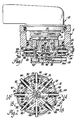
- a fuel injection apparatus 10 is received in a body 11 and has a cylindrical base 12 that is threaded into an upper portion 14.
- Upper portion 14 has a cylindrical filter element 16 surrounding a fuel inlet region, and a solenoid operated valve element 17 that overlies a plurality of fuel discharge passages 18 formed in cylindrical base 12.
- Each fuel discharge passage 18 extends through a (radially directed) feed passage 20 to a (radially opening) recess 22 that receives an injection tube 24.
- each injection tube 24 is flared and received against a stepped shoulder 28 at the intersection of its recess 22 and its feed passage 20.
- Each injection tube 24 is surrounded by an O-ring 30 that seals the injection tube 24 in its recess 22.
- Each injection tube 24 is further surrounded by a plastic sleeve 32 that supports the injection tube 24 in its recess 22.
- a retainer clip 34 has a base portion 36a that underlies the bottom 38 of cylindrical base 12, and a cylindrical portion 36b divided into spring fingers 40 that embrace injection tubes 24.
- the curled upper (free) end 42 of each spring finger 40 flexes outwardly to lead over the rounded ends 44 of plastic sleeves 32.
- the spring fingers 40 then bias plastic sleeves 32, and hence injection tubes 24 to retain the ends 26 of injection tubes 24 in their recesses 22, while the rounded ends 44 of plastic sleeves 32 assist in holding retainer clip 34 on cylindrical base 12. This structure thereby assures that injection tubes 24 may be readily connected to and retained by the fuel injection apparatus 10.
- Air inlet adapter 46 is secured by bolts 48 to the bottom 38 of cylindrical base 12 and also assists in holding retainer clip 34 on cylindrical base 12.
- Air inlet adapter 46 has an inlet tube 50 that leads clean air to an air inlet passage 52.
- Air inlet passage 52 opens through the bottom wall 54 of a rectifier valve chamber 56 defined between cylindrical base 12 and air inlet adapter 46.
- An air outlet passage 58 opens through the top wall 60 of rectifier valve chamber 56 and extends to a plurality of air discharge passages 62, each opening radially into one of the feed passages 20.
- a rectifier valve disc 64 is enclosed in rectifier valve chamber 56 and has a flat valving surface 66 adjacent air inlet passage 52 and an irregular surface 68 adjacent air outlet passage 58.
- solenoid operated valve element 17 When solenoid operated valve element 17 is opened to meter fuel through fuel discharge passages 18, the pressure in feed passages 20 and air discharge and outlet passages 62 and 58 increases to engage the flat valving surface 66 of rectifier valve disc 64 against the bottom wall 54 of rectifier valve chamber 56 about air inlet passage 52, thereby sealing air inlet passage 52.
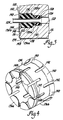
- a fuel injection apparatus 110 has a cylindrical base 112 with a plurality of (radially directed) feed passages 120 extending to (radially opening) recesses 122 that receive injection tubes 124.
- each injection tube 124 is flared and received against a shoulder 128 at the intersection of its recess 122 and its feed passage 120, each injection tube 124 is surrounded by an O-ring 130 that seals the injection tube 124 in its recess 122, and each injection tube 124 is further surrounded by a plastic sleeve 132 that supports the injection tube 124 in its recess 122.
- each plastic sleeve 132 has a shoulder 133a that engages a complementary shoulder 133b in its recess 122.
- a retainer clip 134 has a base portion 136a that underlies the bottom 138 of injector base 112, and a cylindrical portion 136b divided into spring fingers 140 that embrace injection tubes 124. As retainer clip 134 is placed onto cylindrical base 112, the curled upper end 142 of each spring finger 140 flexes outwardly to lead over the rounded ends 144 of plastic sleeves 132. The spring fingers 140 then bias plastic sleeves 132 to retain the ends 126 of injection tubes 124 in their recesses 122.
- Base portion 136a and the lower end of cylindrical portion 136b are divided into flexible tabs 145 by slits 147.
- Each flexible tab 145 has an inwardly directed ridge 149 that engages in a groove 151 circumferentially surrounding cylindrical base 112, thereby securing retainer clip 134 to cylindrical base 112. This structure thereby assures that injection tubes 124 may be readily connected to and retained by fuel injection apparatus 110.
Landscapes
- Engineering & Computer Science (AREA)
- General Engineering & Computer Science (AREA)
- Mechanical Engineering (AREA)
- Chemical & Material Sciences (AREA)
- Combustion & Propulsion (AREA)
- Fuel-Injection Apparatus (AREA)
Priority Applications (1)
| Application Number | Priority Date | Filing Date | Title |
|---|---|---|---|
| AT88305880T ATE65295T1 (de) | 1987-08-03 | 1988-06-28 | Brennstoffeinspritzvorrichtung. |
Applications Claiming Priority (2)
| Application Number | Priority Date | Filing Date | Title |
|---|---|---|---|
| US80831 | 1987-08-03 | ||
| US07/080,831 US4909220A (en) | 1987-08-03 | 1987-08-03 | Fuel injection |
Publications (2)
| Publication Number | Publication Date |
|---|---|
| EP0303344A1 true EP0303344A1 (fr) | 1989-02-15 |
| EP0303344B1 EP0303344B1 (fr) | 1991-07-17 |
Family
ID=22159892
Family Applications (1)
| Application Number | Title | Priority Date | Filing Date |
|---|---|---|---|
| EP88305880A Expired - Lifetime EP0303344B1 (fr) | 1987-08-03 | 1988-06-28 | Dispositif d'injection de combustible |
Country Status (5)
| Country | Link |
|---|---|
| US (1) | US4909220A (fr) |
| EP (1) | EP0303344B1 (fr) |
| AT (1) | ATE65295T1 (fr) |
| CA (1) | CA1308975C (fr) |
| DE (1) | DE3863717D1 (fr) |
Cited By (2)
| Publication number | Priority date | Publication date | Assignee | Title |
|---|---|---|---|---|
| WO1991014093A1 (fr) * | 1990-03-12 | 1991-09-19 | Robert Bosch Gmbh | Dispositif d'injection d'un melange carburant/gaz |
| WO1991014865A1 (fr) * | 1990-03-23 | 1991-10-03 | Robert Bosch Gmbh | Dispositif pour l'injection d'un melange carburant-gaz |
Families Citing this family (7)
| Publication number | Priority date | Publication date | Assignee | Title |
|---|---|---|---|---|
| US5101800A (en) * | 1990-12-07 | 1992-04-07 | General Motors Corporation | Fuel injection |
| US5119793A (en) * | 1990-12-07 | 1992-06-09 | General Motors Corporation | Fuel injection |
| US5341785A (en) * | 1992-07-20 | 1994-08-30 | Echlin, Inc. | Fuel delivery system for internal combustion engines |
| US5463997A (en) * | 1994-10-05 | 1995-11-07 | Cutler Induction Systems, Inc. | Single point fuel injection system |
| CA2246368A1 (fr) * | 1996-02-12 | 1997-08-21 | Filterwerk Mann & Hummel Gmbh | Systeme d'admission |
| DE19719945A1 (de) * | 1996-05-14 | 1997-11-20 | Nok Corp | Kraftstoffeinspritzsystem |
| US5865157A (en) * | 1997-09-04 | 1999-02-02 | Pacer Industries, Inc. | Cam actuated fuel distributor |
Citations (5)
| Publication number | Priority date | Publication date | Assignee | Title |
|---|---|---|---|---|
| US3227147A (en) * | 1959-07-15 | 1966-01-04 | Gossiaux Camille | Shock absorbing tubing for diesel engine fuel injection systems |
| DE3316979A1 (de) * | 1983-05-09 | 1984-11-15 | Jürgen Dipl.-Ing. 8402 Neutraubling Guido | Druckanschluss einer kraftstoff-einspritzleitung fuer verbrennungskraftmaschinen |
| DE3320469A1 (de) * | 1983-06-07 | 1984-12-13 | Volkswagenwerk Ag, 3180 Wolfsburg | Vorrichtung zur verteilung einer zweiphasenstroemung |
| FR2551835A1 (fr) * | 1983-09-13 | 1985-03-15 | Teves Gmbh Alfred | Joint de raccordement entre un tube et un canal agence dans un recipient |
| EP0238156A1 (fr) * | 1986-02-14 | 1987-09-23 | General Motors Corporation | Connexion pour combustible |
Family Cites Families (6)
| Publication number | Priority date | Publication date | Assignee | Title |
|---|---|---|---|---|
| US2913231A (en) * | 1957-01-16 | 1959-11-17 | Continental Motors Corp | Fuel manifold |
| US3845748A (en) * | 1972-09-29 | 1974-11-05 | Mack Trucks | Fuel injection nozzle holder installation |
| FR2214824B1 (fr) * | 1973-01-19 | 1978-12-01 | Peugeot & Renault | |
| DE3146889C2 (de) * | 1981-11-26 | 1986-04-30 | Bayerische Motoren Werke AG, 8000 München | Kraftstoffeinspritzanordnung für Brennkraftmaschinen |
| US4570598A (en) * | 1985-04-15 | 1986-02-18 | Ford Motor Company | Air assist fuel distributor type fuel injection system |
| CA1292651C (fr) * | 1986-05-02 | 1991-12-03 | Ernest R. Stettner | Injection de carburant |
-
1987
- 1987-08-03 US US07/080,831 patent/US4909220A/en not_active Expired - Fee Related
-
1988
- 1988-06-28 DE DE8888305880T patent/DE3863717D1/de not_active Expired - Lifetime
- 1988-06-28 AT AT88305880T patent/ATE65295T1/de not_active IP Right Cessation
- 1988-06-28 EP EP88305880A patent/EP0303344B1/fr not_active Expired - Lifetime
- 1988-08-02 CA CA000573615A patent/CA1308975C/fr not_active Expired - Lifetime
Patent Citations (5)
| Publication number | Priority date | Publication date | Assignee | Title |
|---|---|---|---|---|
| US3227147A (en) * | 1959-07-15 | 1966-01-04 | Gossiaux Camille | Shock absorbing tubing for diesel engine fuel injection systems |
| DE3316979A1 (de) * | 1983-05-09 | 1984-11-15 | Jürgen Dipl.-Ing. 8402 Neutraubling Guido | Druckanschluss einer kraftstoff-einspritzleitung fuer verbrennungskraftmaschinen |
| DE3320469A1 (de) * | 1983-06-07 | 1984-12-13 | Volkswagenwerk Ag, 3180 Wolfsburg | Vorrichtung zur verteilung einer zweiphasenstroemung |
| FR2551835A1 (fr) * | 1983-09-13 | 1985-03-15 | Teves Gmbh Alfred | Joint de raccordement entre un tube et un canal agence dans un recipient |
| EP0238156A1 (fr) * | 1986-02-14 | 1987-09-23 | General Motors Corporation | Connexion pour combustible |
Cited By (2)
| Publication number | Priority date | Publication date | Assignee | Title |
|---|---|---|---|---|
| WO1991014093A1 (fr) * | 1990-03-12 | 1991-09-19 | Robert Bosch Gmbh | Dispositif d'injection d'un melange carburant/gaz |
| WO1991014865A1 (fr) * | 1990-03-23 | 1991-10-03 | Robert Bosch Gmbh | Dispositif pour l'injection d'un melange carburant-gaz |
Also Published As
| Publication number | Publication date |
|---|---|
| US4909220A (en) | 1990-03-20 |
| CA1308975C (fr) | 1992-10-20 |
| ATE65295T1 (de) | 1991-08-15 |
| EP0303344B1 (fr) | 1991-07-17 |
| DE3863717D1 (de) | 1991-08-22 |
Similar Documents
| Publication | Publication Date | Title |
|---|---|---|
| US5390638A (en) | Fuel rail assembly | |
| EP0303344B1 (fr) | Dispositif d'injection de combustible | |
| CA2062790A1 (fr) | Vanne de regulation en plastique | |
| US6136183A (en) | Relief valve for filter device | |
| US4649884A (en) | Fuel rail for internal combustion engines | |
| KR0159105B1 (ko) | V형 엔진용 연료레일 | |
| CN101466942B (zh) | 燃料过滤器 | |
| EP0121978A2 (fr) | Joint d'étanchéité de filtre avec anneau de renforcement | |
| WO1998019770A1 (fr) | Dispositif de filtrage de carburant et de separation de l'eau equipe d'un element chauffant | |
| MXPA02003228A (es) | Conjunto de filtro de fluido de paso dual y elemento para el mismo. | |
| CA2068820A1 (fr) | Dispositif de montage d'un injecteur sur une rampe d'alimentation | |
| JPS585464A (ja) | 噴射弁 | |
| US4741315A (en) | Pressure regulating apparatus | |
| EP0967387A3 (fr) | Filtre pour injecteurs de carburant | |
| DE3071212D1 (en) | Digital fluid flow control apparatus | |
| EP0597888A1 (fr) | Electrovanne de purge de cartouche filtrante a pentes multiples. | |
| US4768720A (en) | Fuel injection | |
| CA2123196A1 (fr) | Filtre a carburant avec orifice de vidange/remplissage/captage | |
| US5275203A (en) | Pressure regulator with plastic vacuum fitting | |
| WO2001042692A8 (fr) | Appareil a clapet de stockage de carburant | |
| CA1130161A (fr) | Tube doseur avec clapet antiretour a bille | |
| US4883088A (en) | Pressure regulating apparatus | |
| JPH0245655A (ja) | 燃料射出装置 | |
| JP2659579B2 (ja) | 調圧弁 | |
| US4580722A (en) | Fuel injection nozzles |
Legal Events
| Date | Code | Title | Description |
|---|---|---|---|
| PUAI | Public reference made under article 153(3) epc to a published international application that has entered the european phase |
Free format text: ORIGINAL CODE: 0009012 |
|
| AK | Designated contracting states |
Kind code of ref document: A1 Designated state(s): AT DE FR GB IT |
|
| 17P | Request for examination filed |
Effective date: 19890404 |
|
| 17Q | First examination report despatched |
Effective date: 19900420 |
|
| ITF | It: translation for a ep patent filed | ||
| GRAA | (expected) grant |
Free format text: ORIGINAL CODE: 0009210 |
|
| AK | Designated contracting states |
Kind code of ref document: B1 Designated state(s): AT DE FR GB IT |
|
| REF | Corresponds to: |
Ref document number: 65295 Country of ref document: AT Date of ref document: 19910815 Kind code of ref document: T |
|
| REF | Corresponds to: |
Ref document number: 3863717 Country of ref document: DE Date of ref document: 19910822 |
|
| ET | Fr: translation filed | ||
| PLBE | No opposition filed within time limit |
Free format text: ORIGINAL CODE: 0009261 |
|
| STAA | Information on the status of an ep patent application or granted ep patent |
Free format text: STATUS: NO OPPOSITION FILED WITHIN TIME LIMIT |
|
| 26N | No opposition filed | ||
| PGFP | Annual fee paid to national office [announced via postgrant information from national office to epo] |
Ref country code: GB Payment date: 19940531 Year of fee payment: 7 |
|
| PGFP | Annual fee paid to national office [announced via postgrant information from national office to epo] |
Ref country code: AT Payment date: 19940610 Year of fee payment: 7 |
|
| PGFP | Annual fee paid to national office [announced via postgrant information from national office to epo] |
Ref country code: FR Payment date: 19940628 Year of fee payment: 7 |
|
| PG25 | Lapsed in a contracting state [announced via postgrant information from national office to epo] |
Ref country code: GB Effective date: 19950628 Ref country code: AT Effective date: 19950628 |
|
| GBPC | Gb: european patent ceased through non-payment of renewal fee |
Effective date: 19950628 |
|
| PG25 | Lapsed in a contracting state [announced via postgrant information from national office to epo] |
Ref country code: FR Effective date: 19960229 |
|
| REG | Reference to a national code |
Ref country code: FR Ref legal event code: ST |
|
| PGFP | Annual fee paid to national office [announced via postgrant information from national office to epo] |
Ref country code: DE Payment date: 20000810 Year of fee payment: 13 |
|
| PG25 | Lapsed in a contracting state [announced via postgrant information from national office to epo] |
Ref country code: DE Free format text: LAPSE BECAUSE OF NON-PAYMENT OF DUE FEES Effective date: 20020403 |
|
| PG25 | Lapsed in a contracting state [announced via postgrant information from national office to epo] |
Ref country code: IT Free format text: LAPSE BECAUSE OF NON-PAYMENT OF DUE FEES;WARNING: LAPSES OF ITALIAN PATENTS WITH EFFECTIVE DATE BEFORE 2007 MAY HAVE OCCURRED AT ANY TIME BEFORE 2007. THE CORRECT EFFECTIVE DATE MAY BE DIFFERENT FROM THE ONE RECORDED. Effective date: 20050628 |