EP0303436A1 - Schädelbohrer, versehen mit einer verbesserten Befestigungshülse - Google Patents
Schädelbohrer, versehen mit einer verbesserten Befestigungshülse Download PDFInfo
- Publication number
- EP0303436A1 EP0303436A1 EP88307337A EP88307337A EP0303436A1 EP 0303436 A1 EP0303436 A1 EP 0303436A1 EP 88307337 A EP88307337 A EP 88307337A EP 88307337 A EP88307337 A EP 88307337A EP 0303436 A1 EP0303436 A1 EP 0303436A1
- Authority
- EP
- European Patent Office
- Prior art keywords
- sleeve
- drill
- ring
- annular
- retaining ring
- Prior art date
- Legal status (The legal status is an assumption and is not a legal conclusion. Google has not performed a legal analysis and makes no representation as to the accuracy of the status listed.)
- Granted
Links
- 210000000988 bone and bone Anatomy 0.000 claims abstract description 6
- 238000005553 drilling Methods 0.000 claims abstract 2
- 238000003466 welding Methods 0.000 claims description 15
- 230000006872 improvement Effects 0.000 claims description 3
- 210000003625 skull Anatomy 0.000 abstract description 5
- 229920003023 plastic Polymers 0.000 abstract description 3
- 239000004033 plastic Substances 0.000 abstract description 3
- 238000000034 method Methods 0.000 description 12
- 230000008569 process Effects 0.000 description 7
- 239000012815 thermoplastic material Substances 0.000 description 6
- 239000000463 material Substances 0.000 description 5
- 229920000122 acrylonitrile butadiene styrene Polymers 0.000 description 4
- 238000004026 adhesive bonding Methods 0.000 description 4
- 230000007246 mechanism Effects 0.000 description 3
- 230000004323 axial length Effects 0.000 description 2
- 239000002184 metal Substances 0.000 description 2
- 230000001954 sterilising effect Effects 0.000 description 2
- 238000004659 sterilization and disinfection Methods 0.000 description 2
- 238000013459 approach Methods 0.000 description 1
- 210000004556 brain Anatomy 0.000 description 1
- 238000004140 cleaning Methods 0.000 description 1
- 238000005520 cutting process Methods 0.000 description 1
- 210000001503 joint Anatomy 0.000 description 1
- 238000012986 modification Methods 0.000 description 1
- 230000004048 modification Effects 0.000 description 1
- 238000002360 preparation method Methods 0.000 description 1
- 230000001681 protective effect Effects 0.000 description 1
- 229920001187 thermosetting polymer Polymers 0.000 description 1
Images


Classifications
-
- B—PERFORMING OPERATIONS; TRANSPORTING
- B29—WORKING OF PLASTICS; WORKING OF SUBSTANCES IN A PLASTIC STATE IN GENERAL
- B29C—SHAPING OR JOINING OF PLASTICS; SHAPING OF MATERIAL IN A PLASTIC STATE, NOT OTHERWISE PROVIDED FOR; AFTER-TREATMENT OF THE SHAPED PRODUCTS, e.g. REPAIRING
- B29C65/00—Joining or sealing of preformed parts, e.g. welding of plastics materials; Apparatus therefor
- B29C65/02—Joining or sealing of preformed parts, e.g. welding of plastics materials; Apparatus therefor by heating, with or without pressure
- B29C65/08—Joining or sealing of preformed parts, e.g. welding of plastics materials; Apparatus therefor by heating, with or without pressure using ultrasonic vibrations
-
- A—HUMAN NECESSITIES
- A61—MEDICAL OR VETERINARY SCIENCE; HYGIENE
- A61B—DIAGNOSIS; SURGERY; IDENTIFICATION
- A61B17/00—Surgical instruments, devices or methods
- A61B17/16—Instruments for performing osteoclasis; Drills or chisels for bones; Trepans
- A61B17/1695—Trepans or craniotomes, i.e. specially adapted for drilling thin bones such as the skull
-
- B—PERFORMING OPERATIONS; TRANSPORTING
- B29—WORKING OF PLASTICS; WORKING OF SUBSTANCES IN A PLASTIC STATE IN GENERAL
- B29C—SHAPING OR JOINING OF PLASTICS; SHAPING OF MATERIAL IN A PLASTIC STATE, NOT OTHERWISE PROVIDED FOR; AFTER-TREATMENT OF THE SHAPED PRODUCTS, e.g. REPAIRING
- B29C66/00—General aspects of processes or apparatus for joining preformed parts
- B29C66/01—General aspects dealing with the joint area or with the area to be joined
- B29C66/05—Particular design of joint configurations
- B29C66/10—Particular design of joint configurations particular design of the joint cross-sections
- B29C66/11—Joint cross-sections comprising a single joint-segment, i.e. one of the parts to be joined comprising a single joint-segment in the joint cross-section
- B29C66/112—Single lapped joints
- B29C66/1122—Single lap to lap joints, i.e. overlap joints
-
- B—PERFORMING OPERATIONS; TRANSPORTING
- B29—WORKING OF PLASTICS; WORKING OF SUBSTANCES IN A PLASTIC STATE IN GENERAL
- B29C—SHAPING OR JOINING OF PLASTICS; SHAPING OF MATERIAL IN A PLASTIC STATE, NOT OTHERWISE PROVIDED FOR; AFTER-TREATMENT OF THE SHAPED PRODUCTS, e.g. REPAIRING
- B29C66/00—General aspects of processes or apparatus for joining preformed parts
- B29C66/50—General aspects of joining tubular articles; General aspects of joining long products, i.e. bars or profiled elements; General aspects of joining single elements to tubular articles, hollow articles or bars; General aspects of joining several hollow-preforms to form hollow or tubular articles
- B29C66/51—Joining tubular articles, profiled elements or bars; Joining single elements to tubular articles, hollow articles or bars; Joining several hollow-preforms to form hollow or tubular articles
- B29C66/53—Joining single elements to tubular articles, hollow articles or bars
- B29C66/532—Joining single elements to the wall of tubular articles, hollow articles or bars
- B29C66/5324—Joining single elements to the wall of tubular articles, hollow articles or bars said single elements being substantially annular, i.e. of finite length
- B29C66/53241—Joining single elements to the wall of tubular articles, hollow articles or bars said single elements being substantially annular, i.e. of finite length said articles being tubular and said substantially annular single elements being of finite length relative to the infinite length of said tubular articles
-
- B—PERFORMING OPERATIONS; TRANSPORTING
- B29—WORKING OF PLASTICS; WORKING OF SUBSTANCES IN A PLASTIC STATE IN GENERAL
- B29C—SHAPING OR JOINING OF PLASTICS; SHAPING OF MATERIAL IN A PLASTIC STATE, NOT OTHERWISE PROVIDED FOR; AFTER-TREATMENT OF THE SHAPED PRODUCTS, e.g. REPAIRING
- B29C66/00—General aspects of processes or apparatus for joining preformed parts
- B29C66/50—General aspects of joining tubular articles; General aspects of joining long products, i.e. bars or profiled elements; General aspects of joining single elements to tubular articles, hollow articles or bars; General aspects of joining several hollow-preforms to form hollow or tubular articles
- B29C66/61—Joining from or joining on the inside
- B29C66/612—Making circumferential joints
-
- B—PERFORMING OPERATIONS; TRANSPORTING
- B29—WORKING OF PLASTICS; WORKING OF SUBSTANCES IN A PLASTIC STATE IN GENERAL
- B29C—SHAPING OR JOINING OF PLASTICS; SHAPING OF MATERIAL IN A PLASTIC STATE, NOT OTHERWISE PROVIDED FOR; AFTER-TREATMENT OF THE SHAPED PRODUCTS, e.g. REPAIRING
- B29C66/00—General aspects of processes or apparatus for joining preformed parts
- B29C66/70—General aspects of processes or apparatus for joining preformed parts characterised by the composition, physical properties or the structure of the material of the parts to be joined; Joining with non-plastics material
- B29C66/71—General aspects of processes or apparatus for joining preformed parts characterised by the composition, physical properties or the structure of the material of the parts to be joined; Joining with non-plastics material characterised by the composition of the plastics material of the parts to be joined
-
- B—PERFORMING OPERATIONS; TRANSPORTING
- B29—WORKING OF PLASTICS; WORKING OF SUBSTANCES IN A PLASTIC STATE IN GENERAL
- B29C—SHAPING OR JOINING OF PLASTICS; SHAPING OF MATERIAL IN A PLASTIC STATE, NOT OTHERWISE PROVIDED FOR; AFTER-TREATMENT OF THE SHAPED PRODUCTS, e.g. REPAIRING
- B29C66/00—General aspects of processes or apparatus for joining preformed parts
- B29C66/70—General aspects of processes or apparatus for joining preformed parts characterised by the composition, physical properties or the structure of the material of the parts to be joined; Joining with non-plastics material
- B29C66/73—General aspects of processes or apparatus for joining preformed parts characterised by the composition, physical properties or the structure of the material of the parts to be joined; Joining with non-plastics material characterised by the intensive physical properties of the material of the parts to be joined, by the optical properties of the material of the parts to be joined, by the extensive physical properties of the parts to be joined, by the state of the material of the parts to be joined or by the material of the parts to be joined being a thermoplastic or a thermoset
- B29C66/739—General aspects of processes or apparatus for joining preformed parts characterised by the composition, physical properties or the structure of the material of the parts to be joined; Joining with non-plastics material characterised by the intensive physical properties of the material of the parts to be joined, by the optical properties of the material of the parts to be joined, by the extensive physical properties of the parts to be joined, by the state of the material of the parts to be joined or by the material of the parts to be joined being a thermoplastic or a thermoset characterised by the material of the parts to be joined being a thermoplastic or a thermoset
- B29C66/7392—General aspects of processes or apparatus for joining preformed parts characterised by the composition, physical properties or the structure of the material of the parts to be joined; Joining with non-plastics material characterised by the intensive physical properties of the material of the parts to be joined, by the optical properties of the material of the parts to be joined, by the extensive physical properties of the parts to be joined, by the state of the material of the parts to be joined or by the material of the parts to be joined being a thermoplastic or a thermoset characterised by the material of the parts to be joined being a thermoplastic or a thermoset characterised by the material of at least one of the parts being a thermoplastic
- B29C66/73921—General aspects of processes or apparatus for joining preformed parts characterised by the composition, physical properties or the structure of the material of the parts to be joined; Joining with non-plastics material characterised by the intensive physical properties of the material of the parts to be joined, by the optical properties of the material of the parts to be joined, by the extensive physical properties of the parts to be joined, by the state of the material of the parts to be joined or by the material of the parts to be joined being a thermoplastic or a thermoset characterised by the material of the parts to be joined being a thermoplastic or a thermoset characterised by the material of at least one of the parts being a thermoplastic characterised by the materials of both parts being thermoplastics
-
- B—PERFORMING OPERATIONS; TRANSPORTING
- B29—WORKING OF PLASTICS; WORKING OF SUBSTANCES IN A PLASTIC STATE IN GENERAL
- B29C—SHAPING OR JOINING OF PLASTICS; SHAPING OF MATERIAL IN A PLASTIC STATE, NOT OTHERWISE PROVIDED FOR; AFTER-TREATMENT OF THE SHAPED PRODUCTS, e.g. REPAIRING
- B29C66/00—General aspects of processes or apparatus for joining preformed parts
- B29C66/70—General aspects of processes or apparatus for joining preformed parts characterised by the composition, physical properties or the structure of the material of the parts to be joined; Joining with non-plastics material
- B29C66/73—General aspects of processes or apparatus for joining preformed parts characterised by the composition, physical properties or the structure of the material of the parts to be joined; Joining with non-plastics material characterised by the intensive physical properties of the material of the parts to be joined, by the optical properties of the material of the parts to be joined, by the extensive physical properties of the parts to be joined, by the state of the material of the parts to be joined or by the material of the parts to be joined being a thermoplastic or a thermoset
- B29C66/739—General aspects of processes or apparatus for joining preformed parts characterised by the composition, physical properties or the structure of the material of the parts to be joined; Joining with non-plastics material characterised by the intensive physical properties of the material of the parts to be joined, by the optical properties of the material of the parts to be joined, by the extensive physical properties of the parts to be joined, by the state of the material of the parts to be joined or by the material of the parts to be joined being a thermoplastic or a thermoset characterised by the material of the parts to be joined being a thermoplastic or a thermoset
- B29C66/7394—General aspects of processes or apparatus for joining preformed parts characterised by the composition, physical properties or the structure of the material of the parts to be joined; Joining with non-plastics material characterised by the intensive physical properties of the material of the parts to be joined, by the optical properties of the material of the parts to be joined, by the extensive physical properties of the parts to be joined, by the state of the material of the parts to be joined or by the material of the parts to be joined being a thermoplastic or a thermoset characterised by the material of the parts to be joined being a thermoplastic or a thermoset characterised by the material of at least one of the parts being a thermoset
-
- Y—GENERAL TAGGING OF NEW TECHNOLOGICAL DEVELOPMENTS; GENERAL TAGGING OF CROSS-SECTIONAL TECHNOLOGIES SPANNING OVER SEVERAL SECTIONS OF THE IPC; TECHNICAL SUBJECTS COVERED BY FORMER USPC CROSS-REFERENCE ART COLLECTIONS [XRACs] AND DIGESTS
- Y10—TECHNICAL SUBJECTS COVERED BY FORMER USPC
- Y10T—TECHNICAL SUBJECTS COVERED BY FORMER US CLASSIFICATION
- Y10T408/00—Cutting by use of rotating axially moving tool
- Y10T408/70—Tool or tool-support with torque-applying clutch
Definitions
- This invention relates to a drill for use by medical practitioners in operations performed on the skull or other bone structure, and more particularly, an improved assembly sleeve for such a drill.
- sleeve 70 of that patent includes a raised portion 74 extending circumferentially on sleeve 70, partially thereabout and is axially aligned with a recess 14 on drill body 10. Raised portion 74 may be deformed radially inwardly to engage recess 14 on drill body 10 to hold sleeve 70 and driver 50 on drill body 10.
- the present invention is an improvement to the cranial drill as shown in U.S. Patent No. 4,456,010.
- That drill includes a primary drill member, a driver with its distal end aligned with the proximal end of the primary drill member, a clutch mechanism connecting the primary drill member and the driver to allow the primary drill member and the driver to rotate together and drill into bone structure and when the clutch is disengaged to permit the primary drill member to remain stationary while the driver rotates.
- the prior drill also includes an annular drill body into which the primary drill member and the driver slide.
- the annular drill body includes a recess extending circumferentially about its exterior surface.
- the prior drill also includes an annular sleeve placed about the outer circumference of the drill body and the sleeve has a proximal end which engages the driver.
- the invention of the present application relates to a retaining ring placed in the annular drill body recess.
- the ring may be rigidly affixed to the inside wall of the sleeve so that the sleeve is attached to the annular drill body in a way that permits the sleeve to rotate freely with respect to the annular drill body but prevents longitudinal motion between the two.
- the sleeve holds the drill assembly together.
- the ring means can be two semicircular rings.
- the means for attaching the ring to the inside surface of the sleeve is preferably ultrasonic welding but any method of attachment may be used. If ultrasonic welding is used, the sleeves have an energy directing surface on their outside circumference which is preferably a triangular projection which extends either about the entire circumference of the ring or intermittently about limited portions of each ring. Alternatively the ring can be a C-shaped member which may or may not extend completely about the circumference of the recess in the annular body.
- this C-shape ring will also have a similar energy directing taper which can extend about the entire circumference of the C-shape ring or intermittently about that circumference. If the ring extends completely about the circumference of the recess in the annular body, the joint where the ring meets may be specially designed to fascilitate intimate contact by using, for example, a tongue and groove, an angled slit, a jogged slit or some other desirable configuration.
- the sleeve and the rings are preferably made of any thermoplastic material particulary ABS plastic but any satisfactory materials that can be permanently fixed together by ultrasonic welding, glueing or any other satisfactory means can be used.
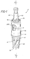
- a drill assembly 2 of the present invention which includes a generally annular drill body 10 having counter bore flutes 12 extending from the distal end, a recess 14 extending circumferentially about drill body 10 close to the proximal end in a generally triangular shaped slot 16 extending through diametrically opposed portions of the wall of drill body 10 (see Figure 2).
- Generally cylindrical primary drill member 30 fits within the distal end of drill body 10 in a clearance fit so that it may rotate and slide in the axial direction freely.
- Drill member 30 includes a stem 36 and a transverse bore 38 therethrough. When the primary drill member 30 is assembled within annular drill body 10, pin 40 extends through slot 16 and through transverse bore 38 to hold primary drill member 30 and drill body 10 together.
- a generally cylindrical driver 50 fits into the other end of drill body 10.
- the distal end 52 of driver 50 includes an axial bore 54 and a coaxial pilot bore 56.
- Transverse slot 68 extends across distal end 52 of driver 50.
- Pilot bore 56 houses spring 58.
- Driver 50 includes a chuck stem 64, which is adapted to engage a chuck of a drill.
- slot 68 When driver 50 is inserted in the proximal end of drill body 10 and when slot 68 is aligned with and pushed against pin 40, slot 68 will capture pin 40 to provide a positive drive mechanism for driving driver 50 and primary drill member 30 together. Pin 40 also engages the edges of slot 16 of drill body 10 to drive drill body 10 along with driver 50.
- Sleeve 70 fits about the periphery of drill body 10 and includes a flange 72 extending radially inward and circumferentially about the proximal end of sleeve 70 to provide means for holding driver 50 in drill body 10.
- recess 14 of drill body 10 receives two retaining rings 200 each of which extends approximately half way about the circumference of recess 14. Rings 200 may be ultrasonically welded to the inside surface of sleeve 70 so that each of rings 200 forms a unitary piece with the sleeve 70 to prevent sleeve 70 from moving axially with respect to recess 14 of drill body 10, and thus to hold driver 50 within drill body 10.
- Figures 4 and 5 show sleeve 70 which includes inwardly extending flange 72 and outwardly extending flange 73 which extend circumferentially about the distal end of sleeve 70 to act as a stop for the forward motion of drill assembly 2.
- each ring 200 is placed in recess 14 to substantially completely fill the circumferential extent of recess 14.
- the outside circumferential surface of each ring 200 includes an energy directing taper 202 which is essentially triangular in shape with the apex of the triangle located approximately at the center of the longitudinal extent of each ring 200.
- the energy directing taper extends completely about the circumference of each retaining ring 200 and has a taper of approximately three degrees (3°).
- This energy directing taper 202 can be a triangular bevel as just described or it can be a convex arch.
- each ring 200 is made is any thermoplastic material and preferably ABS plastic, but can be any material which may be permanently attached to the interior surface of sleeve 70.
- Sleeve 70 is made of any compatible thermosetting plastic but is preferably also made of ABS plastic.
- the material of which ring 200 and sleeve 70 are made may include any material which is capable of being permanently fixed together.
- Ultrasonic bonding is the preferred method of attaching these two parts together, however, any other satisfactory method may be used, for example gluing.
- Energy directing taper 202 is used specifically for ultrasonic welding. If gluing were used the energy directing taper 202 could be eliminated.
- sleeve 70 In preparation for the ultrasonic welding process, two semicircular retaining rings are placed in recess 14 and sleeve 70 is slid into place over the outside of driver 50 and drill body 10.
- a protective sleeve 300 is slid over primary drill member 30 to protect cutting surfaces 32 and abuts against distal end flange 73 of sleeve 70.
- the drill is then placed in jig 302 having two L-shaped brackets, 304 and 306, which can slide with respect to one another along a dovetail slot and groove 308 (shown schematically in Figure 9).
- a cradle 310 is fixed to one of the L brackets 304 to support sleeve 70 of the drill.
- a collar 312 supports the proximal end of the drill in jig 302 so that the proximal end of the drill will not move during the ultrasonic bonding process.
- Sleeve 300 is also affixed to the jig at L-shaped bracket 306 to similarly keep the proximal end of the drill from moving during the ultrasonic bonding process.
- an ultrasonic horn 314 includes a generally semicircular recess at its distal end to closely conform to the outside circumference of sleeve 70.
- the horn 314 preferably covers about a thirty degree (30°) arc so that only a portion of the ring is welded to the inside of the sleeve. This arc angle is not critical and a greater or lesser arc angle may be used.
- jig 302 is slightly compressed by placing L-shaped brackets 304 and 306 in a vice (not shown) to slightly compress the drill during the ultrasonic bonding process so that spring 58 will create no load on the internal parts of the drill during welding and so that the parts will be properly aligned during welding.
- drill body 10 with retaining ring 200 in position with the energy directing taper 202 contacting the interior surface of sleeve 70 and with the ultrasonic welding horn 314 placed against the outside surface of sleeve 70. It can be seen in Figure 10 that there is actual contact between energy directing taper 202 and the inside surface of sleeve 70 during the ultrasonic bonding process.
- two welds are made about one hundred & eighty degrees (180°) apart although more than two welds may be made.
- the drill assembly is placed in the jig and a weld is made. The drill assembly is then rotated one hundred and eighty degrees (180°) and the second weld is made.
- drill body 10 with ring 200 in place in recess 14 with ring 200 bonded to the interior surface of sleeve 70 there is a radial space between the inside circumferential surface of ring 200 and the outside circumferential surface of recess 14 so that ring 200 may rotate freely within recess 14. There is also a space between the outside circumferential surface of drill body 10 and the inside surface of sleeve 70 so that sleeve 70 may rotate freely about the circumference of drill body 10. Ring 200 is captured within recess 14 so that longitudinal motion of drill body 10 with respect to sleeve 70 is prevented so that sleeve 70 holds the drill together.
- the axial length of ring 200 is chosen to be comfortably less than the axial length of recess 14 so that ring 200 will not bind as sleeve 70 rotates about drill body 10 when it is welded to ring 200.
- Figure 12 shows a single C-shaped retaining ring 206 with an energy directing taper 210 extending completely about the circumference of ring 206 in the same fashion as the energy directing taper 202 of retaining ring 200.
- Retaining ring 206 is used in the same way as retaining ring 200 except that, when retaining ring 206 is placed in recess 14, it does not cover the entire circumferential extent of recess 14.
- FIG. 13 there is shown an alternative retaining ring 214 which has the same C-shape as retaining ring 206 except that energy directing taper portions 217 and 219 extend only part way about the outer circumference of ring 214.
- the triangular shape of the energy directing taper can be seen at end portions 216 and 218 of energy directing tapers 217 and 219, respectively.
- the weld between the interior surface of sleeve 70 and ring 214 extends only part way about the circumference of the inside surface of sleeve 70, but it is believed that it is sufficient to provide adequate strength at the joint between ring 214 and the interior surface of sleeve 70.
- FIG 14 there is shown a further alternative embodiment of the ring of the present invention wherein ring 200 is modified to have an energy directing taper extending only part way along its outer circumferential surface.
- the triangular shape of the energy directing taper can be seen at the end portion 224 and 230 of energy directing tapers 226 and 232, respectively.
- multiple energy directing tapers may be spaced along the outer circumferential surface of retaining ring 222 or retaining ring 200.
- FIGS 15-18 there shown still further alternative embodiments of the ring of the present invention.
- Each one of these embodiments provides a special geometry for a single ring which extends completely about the circumstance of recess 14 in annular drill body 10. This feature relates to the slit where the ring comes together. It will be appreciated from Figure 9 that when the entire drill assembly is inserted in jig 302 ready for ultrasonic welding, the operator cannot see whether the slit in the ring is directly under the ultrasonic welder or not.
- the slit is directly under the ultrasonic welder and the ring meets itself at a butt joint running directly transverse to the ring at an angle parallel to the axis of the ring, a slight space can exist so that intimate contact does not occur at the slit.
- FIG. 15 there is shown an alternative ring 240 with an angled slit 242 cut in the direction which is not parallel to the axis of ring 240.
- the inner diameter of ring 240 in the relaxed condition is slightly less than the outer diameter of recess 14 in annular drill body 40, no gap will exist at angle slit 242 and the ring can intimately contact itself at slit 242 to provide a more secure ultrasonic bond even if slit 242 is directly under the ultrasonic welding horn 314.
- Figure 16 shows an alternative ring 244 with a jogged slit 246 so that jogged slit 246 similarly permits ring 244 to intimately contact itself even if it is a little smaller than recess 14.
- Figure 17 shows a further alternative ring 248 with a axially angled slit 250 to similarly permit ring 248 to intimately contact itself even if it is smaller than slot 214.
- Figure 18 shows a further alternative ring 252 with a tongue and groove type slit 254.
- Figure 19 is an exploded perspective view of a modified sleeve 370 with two slots 372 on diametrically opposed portions of sleeve 370 extending completely through the wall of sleeve 370.
- Annular drill body 10 with recess 14 is the same as annular drill body 10 for the embodiment of Figures 1-3.
- One modified ring 400 fits into each of slots 372 to act as a key inserted into recess 14.
- Modified ring 400 is an arcuate ring extending on an arc of about thirty degrees (30°) and is slightly smaller in its outer dimension than the inside dimension of slot 370 so that modified ring 400 may fit easily but snugly into slot 372.
- the radial thickness of modified ring 400 is slightly greater than the combined depth of recess 14 plus the wall thickness of sleeve 370.
- Modified ring 400 may be secured into slot 372 by ultrasonic welding or adhesive bonding as. with the previous embodiment.
- a retaining collar 410 extending completely about the circumference of sleeve 370 over slots 372 and modified ring 400 may be used to hold ring 400 in place.
- a special energy directing slot 412 extending about the arcuate circumference of each ring 400 will except a corresponding projection 414 extending radially inward from the inside surface of retaining collar 410.
- retaining collar 410 and rings 400 are both made of a thermoplastic material particulary ABS plastic so that they may be ultrasonically bonded together in a fashion similar to that of the embodiment of Figures 1-3 by a process similar to that described in connection with Figures 9-11.
- the energy directing bevel shown in Figures 6-8 could be used on the outer circumferential surface of modified ring 400 instead of slot 412 and projection 414 as just described.
- retaining collar 410 could be made of metal and a mechanical connection could be made between the inside surface of metal retaining collar 410 and plastic modified ring 400.
- Either collar 410 or ring 400 must be made of a thermoplastic material so that if the assembled finished drill were attempted to be sterilized by heat or steam the thermoplastic material would melt and destroy the drill so that it could not be used again.
- the particular assembly procedure for this drill is to preferably prohibit the drill from being reused after sterilization. If one attempts to sterilize this drill by heat or steam, the thermoplastic material holding the drill together will melt and destroy the drill thus, the expense of disassembly, cleaning and sterilization and the possible risk of incorrect reassembly are avoided.
Landscapes
- Health & Medical Sciences (AREA)
- Engineering & Computer Science (AREA)
- Mechanical Engineering (AREA)
- Surgery (AREA)
- Life Sciences & Earth Sciences (AREA)
- Biomedical Technology (AREA)
- Medical Informatics (AREA)
- Nuclear Medicine, Radiotherapy & Molecular Imaging (AREA)
- Oral & Maxillofacial Surgery (AREA)
- Dentistry (AREA)
- Neurosurgery (AREA)
- Heart & Thoracic Surgery (AREA)
- Orthopedic Medicine & Surgery (AREA)
- Molecular Biology (AREA)
- Animal Behavior & Ethology (AREA)
- General Health & Medical Sciences (AREA)
- Public Health (AREA)
- Veterinary Medicine (AREA)
- Lining Or Joining Of Plastics Or The Like (AREA)
- Surgical Instruments (AREA)
Applications Claiming Priority (2)
| Application Number | Priority Date | Filing Date | Title |
|---|---|---|---|
| US07/084,233 US4830001A (en) | 1987-08-10 | 1987-08-10 | Assembly sleeve for cranial drill |
| US84233 | 1987-08-10 |
Publications (2)
| Publication Number | Publication Date |
|---|---|
| EP0303436A1 true EP0303436A1 (de) | 1989-02-15 |
| EP0303436B1 EP0303436B1 (de) | 1993-05-19 |
Family
ID=22183662
Family Applications (1)
| Application Number | Title | Priority Date | Filing Date |
|---|---|---|---|
| EP88307337A Expired - Lifetime EP0303436B1 (de) | 1987-08-10 | 1988-08-09 | Schädelbohrer, versehen mit einer verbesserten Befestigungshülse |
Country Status (5)
| Country | Link |
|---|---|
| US (1) | US4830001A (de) |
| EP (1) | EP0303436B1 (de) |
| JP (1) | JP2606893B2 (de) |
| CA (1) | CA1308618C (de) |
| DE (1) | DE3881120T2 (de) |
Cited By (7)
| Publication number | Priority date | Publication date | Assignee | Title |
|---|---|---|---|---|
| US5387218A (en) * | 1990-12-06 | 1995-02-07 | University College London | Surgical instrument for shaping a bone |
| RU2194472C2 (ru) * | 2000-07-06 | 2002-12-20 | Государственное унитарное предприятие "НПО Астрофизика" | Бормашина |
| RU2198610C2 (ru) * | 2000-07-19 | 2003-02-20 | Федеральный научно-производственный центр закрытое акционерное общество "Научно-производственный концерн (объединение) "ЭНЕРГИЯ" | Кольцевое сверло |
| WO2007121057A1 (en) * | 2006-04-10 | 2007-10-25 | Warsaw Orthopedic, Inc. | Multi-piece circumferential retaining ring |
| EP1920720A1 (de) * | 2006-10-13 | 2008-05-14 | Stryker Trauma SA | Mittel zur Verhinderung der Wiederverwendung einer medizinischen Vorrichtung |
| WO2011110874A1 (en) * | 2010-03-12 | 2011-09-15 | Klis Instruments | Device for forming an opening adapted to receive a cranial plug |
| WO2025017493A1 (en) * | 2023-07-19 | 2025-01-23 | Medtronic Xomed Llc | Passive identification for limited-use surgical devices and limited-use disposable attachments |
Families Citing this family (27)
| Publication number | Priority date | Publication date | Assignee | Title |
|---|---|---|---|---|
| IE920024A1 (en) * | 1991-01-15 | 1992-07-15 | Pfizer Hospital Prod | Surgical drill guide |
| US5810828A (en) * | 1997-02-13 | 1998-09-22 | Mednext, Inc. | Adjustable depth drill guide |
| US5876405A (en) * | 1997-09-17 | 1999-03-02 | The Anspach Effort, Inc. | Perforator |
| US6716215B1 (en) | 1999-10-29 | 2004-04-06 | Image-Guided Neurologics | Cranial drill with sterile barrier |
| US7488327B2 (en) | 2004-04-12 | 2009-02-10 | Synthes (U.S.A.) | Free hand drill guide |
| US20090024129A1 (en) * | 2007-07-19 | 2009-01-22 | Jeremy Gordon | Perforator with inner and outer drills and a drive head, the inner drill configured to move against the outer drill in order to disengage from the drive head |
| DE102007036354A1 (de) | 2007-07-31 | 2009-02-05 | Medicon Eg. Chirurgiemechaniker-Genossenschaft | Schädelbohrer |
| US7793560B2 (en) * | 2007-09-11 | 2010-09-14 | Black & Decker Inc. | Transmission and variable radially expanding spring clutch assembly |
| USD596743S1 (en) | 2007-10-29 | 2009-07-21 | Codman & Shurtleff, Inc. | Cranial perforator |
| US20090228011A1 (en) * | 2007-10-29 | 2009-09-10 | Agbodoe Victor B | Cranial perforator |
| WO2009117836A1 (en) * | 2008-03-28 | 2009-10-01 | Quanser Consulting Inc. | Drill assembly and method to reduce drill bit plunge |
| US8109183B2 (en) | 2008-06-06 | 2012-02-07 | Black & Decker Inc. | Impact resistant tool bit and tool bit holder |
| DE102008030942A1 (de) | 2008-07-02 | 2010-01-07 | Christoph Miethke Gmbh & Co Kg | Hirnwasserdrainagen |
| US8540580B2 (en) | 2009-08-12 | 2013-09-24 | Black & Decker Inc. | Tool bit or tool holder for power tool |
| US20150094733A1 (en) * | 2010-05-04 | 2015-04-02 | Samuel Shiber | Rotary catheter drive unit containing seal-sets |
| CA2835616A1 (en) * | 2011-05-10 | 2012-11-15 | Peter Nakaji | Cranial plating and bur hole cover system |
| US9421641B2 (en) * | 2011-12-28 | 2016-08-23 | Raytheon Company | System and method for providing thermal management of an obscured laser system |
| KR101375872B1 (ko) | 2012-05-24 | 2014-03-17 | 박병활 | 치과용 골 채집기 |
| GB201209772D0 (en) | 2012-06-01 | 2012-07-18 | Renishaw Plc | Cranial drill system |
| KR101408909B1 (ko) | 2013-01-11 | 2014-06-18 | 박병활 | 보조드릴이 구비된 상악동 거상술용 임플란트 드릴 |
| CA3151301A1 (en) * | 2018-08-17 | 2020-02-20 | Emd Kft. | Disposable perforator |
| WO2021062857A1 (en) | 2019-10-01 | 2021-04-08 | Apex Brands, Inc. | Ratchet wrench with drive pins |
| EP4090264A4 (de) | 2020-01-16 | 2024-01-17 | Spinal Innovations, LLC | Druckaktiviertes chirurgisches instrument zur verwendung bei wirbelsäulendekomprimierungsverfahren und verwendungsverfahren dafür |
| EP4121242B1 (de) * | 2020-03-18 | 2026-04-15 | Apex Brands, Inc. | Radialbandkeilschlagantriebsvorrichtung |
| CN112022278B (zh) * | 2020-09-30 | 2025-11-04 | 重庆西山科技股份有限公司 | 可调骨垫厚度的颅骨钻头 |
| GB2601302A (en) * | 2020-11-20 | 2022-06-01 | Adeor Medical AG | Apparatus for cutting a hole |
| EP4062842A1 (de) | 2021-03-23 | 2022-09-28 | Antonio Martos Calvo | Auf einen selbstsichernden intrakraniellen bohrer für den einmalgebrauch angewendetes lösesystem und schneidprofil |
Citations (4)
| Publication number | Priority date | Publication date | Assignee | Title |
|---|---|---|---|---|
| US3438824A (en) * | 1965-05-14 | 1969-04-15 | Cavitron Corp | Method and apparatus for joining a closure to a container by high frequency radial vibrations |
| DE2916221B1 (de) * | 1979-04-21 | 1980-03-13 | Aesculap Werke Ag | Schaedeltrepan |
| GB2086279A (en) * | 1980-10-27 | 1982-05-12 | Codman & Shurtleff | Cranial drill |
| DE3405379C1 (de) * | 1984-02-15 | 1985-12-19 | Aesculap-Werke Ag Vormals Jetter & Scheerer, 7200 Tuttlingen | Schädeltrepan |
Family Cites Families (7)
| Publication number | Priority date | Publication date | Assignee | Title |
|---|---|---|---|---|
| US2525669A (en) * | 1947-07-25 | 1950-10-10 | Hainault Marcel | Automatic trepans |
| US3887222A (en) * | 1974-07-25 | 1975-06-03 | Hansen Mfg | Coupling with push-pull release |
| US4142543A (en) * | 1977-02-25 | 1979-03-06 | Henry Valve Company | Valve stem and disc combination and method of assembling same |
| US4365696A (en) * | 1980-11-24 | 1982-12-28 | Warn Industries, Inc. | One-piece locking clutch |
| US4699550A (en) * | 1984-01-31 | 1987-10-13 | Baker John W | Cranial perforator |
| US4544425A (en) * | 1984-03-07 | 1985-10-01 | Stewart-Warner Corporation | Method for attaching wheels to dual wheel casters, including ultrasonic welding |
| US4541612A (en) * | 1984-04-03 | 1985-09-17 | Keystone International, Inc. | Rotatable shaft assembly |
-
1987
- 1987-08-10 US US07/084,233 patent/US4830001A/en not_active Expired - Lifetime
-
1988
- 1988-08-09 DE DE8888307337T patent/DE3881120T2/de not_active Expired - Lifetime
- 1988-08-09 EP EP88307337A patent/EP0303436B1/de not_active Expired - Lifetime
- 1988-08-09 CA CA000574200A patent/CA1308618C/en not_active Expired - Lifetime
- 1988-08-10 JP JP63198107A patent/JP2606893B2/ja not_active Expired - Lifetime
Patent Citations (4)
| Publication number | Priority date | Publication date | Assignee | Title |
|---|---|---|---|---|
| US3438824A (en) * | 1965-05-14 | 1969-04-15 | Cavitron Corp | Method and apparatus for joining a closure to a container by high frequency radial vibrations |
| DE2916221B1 (de) * | 1979-04-21 | 1980-03-13 | Aesculap Werke Ag | Schaedeltrepan |
| GB2086279A (en) * | 1980-10-27 | 1982-05-12 | Codman & Shurtleff | Cranial drill |
| DE3405379C1 (de) * | 1984-02-15 | 1985-12-19 | Aesculap-Werke Ag Vormals Jetter & Scheerer, 7200 Tuttlingen | Schädeltrepan |
Cited By (9)
| Publication number | Priority date | Publication date | Assignee | Title |
|---|---|---|---|---|
| US5387218A (en) * | 1990-12-06 | 1995-02-07 | University College London | Surgical instrument for shaping a bone |
| RU2194472C2 (ru) * | 2000-07-06 | 2002-12-20 | Государственное унитарное предприятие "НПО Астрофизика" | Бормашина |
| RU2198610C2 (ru) * | 2000-07-19 | 2003-02-20 | Федеральный научно-производственный центр закрытое акционерное общество "Научно-производственный концерн (объединение) "ЭНЕРГИЯ" | Кольцевое сверло |
| WO2007121057A1 (en) * | 2006-04-10 | 2007-10-25 | Warsaw Orthopedic, Inc. | Multi-piece circumferential retaining ring |
| EP1920720A1 (de) * | 2006-10-13 | 2008-05-14 | Stryker Trauma SA | Mittel zur Verhinderung der Wiederverwendung einer medizinischen Vorrichtung |
| US8382804B2 (en) | 2006-10-13 | 2013-02-26 | Stryker Trauma Sa | Prevention of re-use of a medical device |
| US9549762B2 (en) | 2006-10-13 | 2017-01-24 | Stryker European Holdings I, Llc | Prevention of re-use of a medical device |
| WO2011110874A1 (en) * | 2010-03-12 | 2011-09-15 | Klis Instruments | Device for forming an opening adapted to receive a cranial plug |
| WO2025017493A1 (en) * | 2023-07-19 | 2025-01-23 | Medtronic Xomed Llc | Passive identification for limited-use surgical devices and limited-use disposable attachments |
Also Published As
| Publication number | Publication date |
|---|---|
| US4830001A (en) | 1989-05-16 |
| JPH0284947A (ja) | 1990-03-26 |
| DE3881120T2 (de) | 1993-09-02 |
| DE3881120D1 (de) | 1993-06-24 |
| JP2606893B2 (ja) | 1997-05-07 |
| EP0303436B1 (de) | 1993-05-19 |
| CA1308618C (en) | 1992-10-13 |
Similar Documents
| Publication | Publication Date | Title |
|---|---|---|
| EP0303436B1 (de) | Schädelbohrer, versehen mit einer verbesserten Befestigungshülse | |
| EP2055335B1 (de) | Verfahren zur Herstellung einer Nadel und Nadel | |
| US4362161A (en) | Cranial drill | |
| EP0481760B1 (de) | Chirurgische Vorrichtung | |
| US20100274140A1 (en) | Method of mounting a transducer to a driveshaft | |
| US5405348A (en) | Surgical cutting instrument | |
| US11701137B2 (en) | Reusable blade hub assembly | |
| CN108882945A (zh) | 用于经皮手术器械和驱动工具的无菌联接的装置以及用于执行这种联接的方法 | |
| JP2026506205A (ja) | カテーテル位置固定用の内蔵された締付ポートを具備するシースハブ | |
| US6089866A (en) | Drive shaft retention means for prophy angle | |
| JP2022077981A (ja) | 歯科用円板ブランクの保定リング | |
| US12247625B2 (en) | Rotational coupling device and method | |
| EP3243450A1 (de) | Bremse für adapteranordnungen für chirurgische vorrichtungen | |
| JPH01312294A (ja) | 可撓ホースの端部を係合部材に固定する装置および方法 | |
| JP3863684B2 (ja) | ハンドピース | |
| JPH0342999B2 (de) | ||
| WO2025234494A1 (ja) | 採血針 | |
| HK40056523A (en) | Lockable quick coupling | |
| JP4093055B2 (ja) | 衛生シート | |
| CA1312515C (en) | Tube assembly with a breakaway plug | |
| JP2022143223A (ja) | カテーテル組立体及びカテーテル組立体の長さ調整方法 | |
| US20190365390A1 (en) | Medical device |
Legal Events
| Date | Code | Title | Description |
|---|---|---|---|
| PUAI | Public reference made under article 153(3) epc to a published international application that has entered the european phase |
Free format text: ORIGINAL CODE: 0009012 |
|
| AK | Designated contracting states |
Kind code of ref document: A1 Designated state(s): BE DE FR GB LU NL |
|
| 17P | Request for examination filed |
Effective date: 19890807 |
|
| 17Q | First examination report despatched |
Effective date: 19911025 |
|
| GRAA | (expected) grant |
Free format text: ORIGINAL CODE: 0009210 |
|
| AK | Designated contracting states |
Kind code of ref document: B1 Designated state(s): BE DE FR GB LU NL |
|
| REF | Corresponds to: |
Ref document number: 3881120 Country of ref document: DE Date of ref document: 19930624 |
|
| ET | Fr: translation filed | ||
| EPTA | Lu: last paid annual fee | ||
| PLBE | No opposition filed within time limit |
Free format text: ORIGINAL CODE: 0009261 |
|
| STAA | Information on the status of an ep patent application or granted ep patent |
Free format text: STATUS: NO OPPOSITION FILED WITHIN TIME LIMIT |
|
| 26N | No opposition filed | ||
| REG | Reference to a national code |
Ref country code: GB Ref legal event code: IF02 |
|
| PGFP | Annual fee paid to national office [announced via postgrant information from national office to epo] |
Ref country code: DE Payment date: 20070802 Year of fee payment: 20 |
|
| PGFP | Annual fee paid to national office [announced via postgrant information from national office to epo] |
Ref country code: LU Payment date: 20070816 Year of fee payment: 20 |
|
| PGFP | Annual fee paid to national office [announced via postgrant information from national office to epo] |
Ref country code: GB Payment date: 20070809 Year of fee payment: 20 |
|
| PGFP | Annual fee paid to national office [announced via postgrant information from national office to epo] |
Ref country code: NL Payment date: 20070723 Year of fee payment: 20 |
|
| PGFP | Annual fee paid to national office [announced via postgrant information from national office to epo] |
Ref country code: BE Payment date: 20071012 Year of fee payment: 20 |
|
| PGFP | Annual fee paid to national office [announced via postgrant information from national office to epo] |
Ref country code: FR Payment date: 20070808 Year of fee payment: 20 |
|
| BE20 | Be: patent expired |
Owner name: *CODMAN & *SHURTLEFF INC. Effective date: 20080809 |
|
| REG | Reference to a national code |
Ref country code: GB Ref legal event code: PE20 Expiry date: 20080808 |
|
| NLV7 | Nl: ceased due to reaching the maximum lifetime of a patent |
Effective date: 20080809 |
|
| PG25 | Lapsed in a contracting state [announced via postgrant information from national office to epo] |
Ref country code: NL Free format text: LAPSE BECAUSE OF EXPIRATION OF PROTECTION Effective date: 20080809 |
|
| PG25 | Lapsed in a contracting state [announced via postgrant information from national office to epo] |
Ref country code: GB Free format text: LAPSE BECAUSE OF EXPIRATION OF PROTECTION Effective date: 20080808 |