EP0303475B1 - Mécanisme de commande pour vanne rotative - Google Patents
Mécanisme de commande pour vanne rotative Download PDFInfo
- Publication number
- EP0303475B1 EP0303475B1 EP88307414A EP88307414A EP0303475B1 EP 0303475 B1 EP0303475 B1 EP 0303475B1 EP 88307414 A EP88307414 A EP 88307414A EP 88307414 A EP88307414 A EP 88307414A EP 0303475 B1 EP0303475 B1 EP 0303475B1
- Authority
- EP
- European Patent Office
- Prior art keywords
- collar
- drive
- ball
- rotary valve
- tundish
- Prior art date
- Legal status (The legal status is an assumption and is not a legal conclusion. Google has not performed a legal analysis and makes no representation as to the accuracy of the status listed.)
- Expired - Lifetime
Links
- 230000007246 mechanism Effects 0.000 title claims description 17
- 230000002093 peripheral effect Effects 0.000 claims description 8
- XKRFYHLGVUSROY-UHFFFAOYSA-N Argon Chemical compound [Ar] XKRFYHLGVUSROY-UHFFFAOYSA-N 0.000 claims description 6
- 229910052786 argon Inorganic materials 0.000 claims description 3
- 238000002347 injection Methods 0.000 claims description 2
- 239000007924 injection Substances 0.000 claims description 2
- 239000007788 liquid Substances 0.000 abstract description 4
- 238000001816 cooling Methods 0.000 description 3
- 230000008878 coupling Effects 0.000 description 3
- 238000010168 coupling process Methods 0.000 description 3
- 238000005859 coupling reaction Methods 0.000 description 3
- 230000001681 protective effect Effects 0.000 description 2
- 238000009628 steelmaking Methods 0.000 description 2
- 229910000831 Steel Inorganic materials 0.000 description 1
- 230000009471 action Effects 0.000 description 1
- 230000005540 biological transmission Effects 0.000 description 1
- 210000005069 ears Anatomy 0.000 description 1
- 230000000694 effects Effects 0.000 description 1
- 239000007789 gas Substances 0.000 description 1
- 230000013011 mating Effects 0.000 description 1
- 230000003278 mimic effect Effects 0.000 description 1
- 239000010959 steel Substances 0.000 description 1
Images




Classifications
-
- F—MECHANICAL ENGINEERING; LIGHTING; HEATING; WEAPONS; BLASTING
- F16—ENGINEERING ELEMENTS AND UNITS; GENERAL MEASURES FOR PRODUCING AND MAINTAINING EFFECTIVE FUNCTIONING OF MACHINES OR INSTALLATIONS; THERMAL INSULATION IN GENERAL
- F16D—COUPLINGS FOR TRANSMITTING ROTATION; CLUTCHES; BRAKES
- F16D3/00—Yielding couplings, i.e. with means permitting movement between the connected parts during the drive
- F16D3/16—Universal joints in which flexibility is produced by means of pivots or sliding or rolling connecting parts
- F16D3/20—Universal joints in which flexibility is produced by means of pivots or sliding or rolling connecting parts one coupling part entering a sleeve of the other coupling part and connected thereto by sliding or rolling members
- F16D3/202—Universal joints in which flexibility is produced by means of pivots or sliding or rolling connecting parts one coupling part entering a sleeve of the other coupling part and connected thereto by sliding or rolling members one coupling part having radially projecting pins, e.g. tripod joints
- F16D3/207—Universal joints in which flexibility is produced by means of pivots or sliding or rolling connecting parts one coupling part entering a sleeve of the other coupling part and connected thereto by sliding or rolling members one coupling part having radially projecting pins, e.g. tripod joints the pins extending radially inwardly from the coupling part
-
- B—PERFORMING OPERATIONS; TRANSPORTING
- B22—CASTING; POWDER METALLURGY
- B22D—CASTING OF METALS; CASTING OF OTHER SUBSTANCES BY THE SAME PROCESSES OR DEVICES
- B22D41/00—Casting melt-holding vessels, e.g. ladles, tundishes, cups or the like
- B22D41/14—Closures
-
- B—PERFORMING OPERATIONS; TRANSPORTING
- B22—CASTING; POWDER METALLURGY
- B22D—CASTING OF METALS; CASTING OF OTHER SUBSTANCES BY THE SAME PROCESSES OR DEVICES
- B22D41/00—Casting melt-holding vessels, e.g. ladles, tundishes, cups or the like
- B22D41/14—Closures
- B22D41/16—Closures stopper-rod type, i.e. a stopper-rod being positioned downwardly through the vessel and the metal therein, for selective registry with the pouring opening
- B22D41/20—Stopper-rod operating equipment
Definitions
- This invention relates to an actuator mechanism for a rotary valve.
- Rotary valves are used in steel making and in other applications where hot and corrosive liquids are handled, the valve being located in the tundish and partially surrounded by liquid which runs through an opening in the valve out of the tundish.
- the rotary valve consists of a domed lower portion which is attached to the lining in the tundish and a stem or 'rotor' which sits on the dome and is rotatable about its longitudinal axis for the purpose of adjusting or closing the opening.
- the stem is supported by and rotated by a known actuator mechanism which consists of a cantilever support having an upright support column located adjacent to the tundish and a cross beam which overlies the tundish and is connected to opposed flats at the upper end of the column.
- a drive means causes the column to rotate in the desired amount in the desired direction.
- said downward load is provided by a pneumatic cylinder and a square section shaft carried with the upright column.
- the pneumatic cylinder pulls the entire cross head downwards but such an arrangement is inefficient in that the force acting on the valve stem is considerably less than the force created by the pneumatic cylinder.
- the arrangement tends to distort the top of the shaft away from the tundish and this can result in the shaft becoming immovable in its upright guide supports.
- An object of this invention is to obviate or mitigate the aforementioned problems.
- an actuator mechanism for a rotary valve comprising an upright support member for location adjacent to a tundish and a cross arm mounted on said upright support member to overlie the tundish, said cross arm being pivotally connected to the upright support member to pivot about a horizontal axis, vertical pressure means to act on the cross arm to cause a load to be applied in the vertical direction at the end adapted to overlie the tundish, and drive means mounted at the end of the cross arm which is adapted to overlie the tundish, said drive means being adapted for connection to the stem of the rotary valve by means of a swivel joint which comprises a drive head of a square section having an end face which has a part spherical socket centrally disposed therein and a ball member having a square collar diametrically disposed such that a sector of the ball extends from opposed sides of the collar one of which sectors and the collar are for location in the drive head with the sector in the socket thereof, the other sector being secured to or integral with a
- a through opening is provided in the drive means, the drive head and the ball for argon injection into the rotary valve.
- a swivel joint device for location between a rotary drive and a rotary driven unit comprising a drive head of square cross section having an end face which has a part spherical socket centrally disposed therein said drive head being for attachment to one of said drive or driven units, and a ball member having a square collar diametrically disposed such that sectors of the ball extend from opposed sides of the collar, one of which and said collar are for location in the drive head with the sector in the socket thereof, the other sector being secured to or integral with a flange for attachment to the other of said drive or driven units, the collar having convex peripheral surfaces which coincide with the curvature of the ball to provide adjustability within the drive head whereby the longitudinal axis through the drive head relative to the swivel joint device may be out of alignment with the axis through the flange.
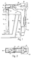
- the actuator mechanism 10 is hooked at 10A and bolted at 10B to a structure 11A alongside a tundish 11 in which is located a refractory rotary valve 12.
- the rotary valve has two components, namely a domed base 13 and an upright rotary stem 14.
- An opening 15 is provided in the domed base and at the lower end of the column 14 and rotation of the stem can alter the size of the opening or close it completely.
- the domed base 13 is secured within the tundish seated in the lining 16 thereof and in use most of the rotary valve is immersed in liquid.
- the uppermost portion of the rotary valve stem 14 extends out of the tundish for connection to the actuator mechanism by which a downward load is applied to the stem 14 to keep it firmly seated on the domed base 13 and a rotary force is applied to alter the opening 15.
- the actuator mechanism 10 comprises an upright support column 20, the upper end 21 of which is angled to overlie at least the peripheral area of the tundish 11.
- a cross arm 22 is pivotally mounted on the upper end 21 of the support column 20 by a horizontal pivot at 23.
- One end 24, the "outer” end, of the cross arm 22 is at the support column 20 and an upright pneumatic or hydraulic jack 25 is fixedly mounted on the support column 20 and connected to that end 24 of the cross arm.
- the other inner end 26 of the cross arm 22 overlies the centre of the tundish 11 and carries drive means in the form of a gearhead 27 which is connected to the rotary valve stem 14 as hereinafter described.
- the gearhead 27 provides the rotary force to the stem 14.
- An air-cooled motor 28 is mounted on the top of the support 20 and drives the gearhead via a flexible splined coupling 29.
- the motor 28 may be electric, hydraulic or pneumatic to suit the environment. With adequate cooling the motor 28 may be mounted directly over the stem 14 and the transmission system dispensed with. This is advantageous where rapid control responses are required.
- the pneumatic or hydraulic jack 25 applies an upward load to the outer end of the pivotal cross arm 22 and that load is translated via the pivot 23 to a downward load at the inner end of the cross arm.
- the amount of downward pressure on the rotary valve stem relative to the upward pneumatic or hydraulic load depends on the position of the pivot 23 relative to the length of the cross arm, but where the pivot is at the midpoint, it is considered that a loss of only 5% would be incurred at the inner end of the cross head.
- the pivot is at a ratio of 3:5 being nearer the inner end of the cross arm so that the downward load will be in the region of 1.7 times that of the applied hydraulic load but that location may vary according to the design of the upright support.
- the cross arm 22 is connected to the upper end of the rotary valve stem 14 by a socket joint designated generally as 30; it comprises a hollow drive head 31 connected to the gearhead 27 on cross arm 22 and rotatable about an axis at 90° to the cross arm, a flange 32 which is attached to a cap 33 which locates over the upper end of the stem 14 and engages opposed flats thereon (not shown) and a steel ball member 34 which is welded to or integral with the flange 32 and locates in the head 31.
- a socket joint designated generally as 30 it comprises a hollow drive head 31 connected to the gearhead 27 on cross arm 22 and rotatable about an axis at 90° to the cross arm, a flange 32 which is attached to a cap 33 which locates over the upper end of the stem 14 and engages opposed flats thereon (not shown) and a steel ball member 34 which is welded to or integral with the flange 32 and locates in the head 31.
- the head 31 is box shaped of square section and has an end face 35 in which a part spherical socket 36 is centrally disposed.
- the ball member has a diametrically peripheral collar 37 (Fig. 4) of square shape in plan, but with convex peripheral sides 38, the convexity being equal to the curvature of the periphery of the ball.
- the length of the sides of the square equals the diameter of the ball so that at the midpoint of each side 38 the convex surface of the peripheral side and the diameter of the ball coincide.
- One face of the collar namely the upper face 39 has a slightly tapering downwards curvature towards the corners.
- each major face of the square collar is a sector 40, 41 of the ball.
- the upper sector 40 locates in the socket 36 and square collar locates in the head 31 when the joint is assembled.
- the lower sector locates in a recess in the flange 32 and is welded therein or alternatively is forged as an integral unit to give the same effect.
- the flange 32 is secured, eg by bolts to the stem cap 33.
- the ball member 34 is secured in the head 31 by locating pins 42, Fig. 3 which pass through at least two opposed sides of the casing and into flared recesses 43 in the ball member 34. This is to allow the degree of movement of the ball member within the head 31 due to the curvature of the collar periphery and upper face and the location of the upper sector 40 of the ball in socket 36.
- the gearhead 27 need not be in direct vertical alignment with the domed base 10 and a slight misalignment of the rotary valve stem 11 is therefore possible.
- the stem cap 33 is of square cross section and tapers downwardly to overlie the top of the rotary valve stem.
- a vertical bore 44 passes through the gearhead and ball joint to accommodate an argon gas feed pipe.
- the bore in the ball member is outwardly flared at 44A in the upper sector to accommodate movement of the ball member within the head 31.
- the ball joint as hereinbefore described may be applied to other apparatus between rotary drive and driven units.
- An actuator mechanism as hereinbefore described has a number of advantages.
- the cross arm and selected other parts of the actuator mechanism are extensively insulated to minimise heat transfer from the tundish, and maintain all mechanical parts within working temperature ranges.
- a mechanical off-take from the motor shaft may be provided, being transmitted though the flexible drive shaft to a mimic so that the operator of the actuator mechanism can be aware of the exact orientation of the stem in relation to the dome during operation.
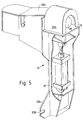
- Fig. 5 shows, in perspective, a modified actuator mechanism 10 in which the motor 28 has a protective cover 28A and the coupling 29 has a protective cover 29A.
- the motor 28 has a protective cover 28A
- the coupling 29 has a protective cover 29A.
- wings 20A having slots 20B.
- Fig. 6 also shows the wings 20A and the slots 20B and the structure 11A having a slot 11B aligned with the slot 20B and both receiving a pin 11C.
- the pin 11C is pivoted at one end between ears 11D on the structure 11A and has a slot therethrough into which slot a cotter pin 11E can be hammered to easily and effectively mount the actuator mechanism 10.
- Fig. 7 shows air-cooling can be applied to the gearhead 27 in Figs. 1 and 2.
- Fig. 8 shows an arrangement wherein two cross arms 22A have their common pivot 23A at one end, instead of intermediate their ends.
- Each cross arm 22A has at its other end a motor 28A, which may be electric, hydraulic or pneumatic.
- the cross arms 22A are yoked together at 22B to be operated in common by a single hydraulic or pneumatic jack 25.
Landscapes
- Engineering & Computer Science (AREA)
- Mechanical Engineering (AREA)
- General Engineering & Computer Science (AREA)
- Mechanically-Actuated Valves (AREA)
- Pivots And Pivotal Connections (AREA)
- Actuator (AREA)
- Fluid-Driven Valves (AREA)
- Casting Support Devices, Ladles, And Melt Control Thereby (AREA)
- Soil Working Implements (AREA)
- Vehicle Body Suspensions (AREA)
- Steering Control In Accordance With Driving Conditions (AREA)
- Fluid-Damping Devices (AREA)
- Taps Or Cocks (AREA)
- Quick-Acting Or Multi-Walled Pipe Joints (AREA)
Claims (3)
Priority Applications (1)
| Application Number | Priority Date | Filing Date | Title |
|---|---|---|---|
| AT88307414T ATE75432T1 (de) | 1987-08-10 | 1988-08-10 | Betaetigungsvorrichtung fuer drehverschluss. |
Applications Claiming Priority (2)
| Application Number | Priority Date | Filing Date | Title |
|---|---|---|---|
| GB8718878 | 1987-08-10 | ||
| GB878718878A GB8718878D0 (en) | 1987-08-10 | 1987-08-10 | Actuator mechanism |
Publications (2)
| Publication Number | Publication Date |
|---|---|
| EP0303475A1 EP0303475A1 (fr) | 1989-02-15 |
| EP0303475B1 true EP0303475B1 (fr) | 1992-04-29 |
Family
ID=10622064
Family Applications (2)
| Application Number | Title | Priority Date | Filing Date |
|---|---|---|---|
| EP88906993A Pending EP0379489A1 (fr) | 1987-08-10 | 1988-08-10 | Mecanisme actuateur pour vanne rotative |
| EP88307414A Expired - Lifetime EP0303475B1 (fr) | 1987-08-10 | 1988-08-10 | Mécanisme de commande pour vanne rotative |
Family Applications Before (1)
| Application Number | Title | Priority Date | Filing Date |
|---|---|---|---|
| EP88906993A Pending EP0379489A1 (fr) | 1987-08-10 | 1988-08-10 | Mecanisme actuateur pour vanne rotative |
Country Status (9)
| Country | Link |
|---|---|
| US (1) | US5033658A (fr) |
| EP (2) | EP0379489A1 (fr) |
| JP (1) | JPH02504488A (fr) |
| AT (1) | ATE75432T1 (fr) |
| AU (1) | AU2138788A (fr) |
| DE (1) | DE3870540D1 (fr) |
| GB (2) | GB8718878D0 (fr) |
| WO (1) | WO1989001374A1 (fr) |
| ZA (1) | ZA885861B (fr) |
Families Citing this family (6)
| Publication number | Priority date | Publication date | Assignee | Title |
|---|---|---|---|---|
| CH678701A5 (fr) * | 1989-03-31 | 1991-10-31 | Stopinc Ag | |
| DE4032084C1 (fr) * | 1990-10-10 | 1992-05-27 | Didier-Werke Ag, 6200 Wiesbaden, De | |
| GB9206394D0 (en) * | 1992-03-24 | 1992-05-06 | Crane Ltd | A stopper device |
| DE4232006A1 (de) * | 1992-09-24 | 1994-03-31 | Leybold Ag | Vorrichtung zum Öffnen und Schließen einer Bodenabgußöffnung in einem Vakuum-Induktionsschmelz- und -gießofen |
| WO1998016337A1 (fr) * | 1996-10-12 | 1998-04-23 | Stopinc Ag | Mecanisme d'entrainement destine a un organe de fermeture et/ou de regulation pour la rigole de coulee d'un reservoir contenant une masse de metal en fusion |
| US12328836B2 (en) | 2022-04-06 | 2025-06-10 | Juniper Networks, Inc. | Self-actuating protective cover device for connectors of a field-replaceable unit |
Family Cites Families (6)
| Publication number | Priority date | Publication date | Assignee | Title |
|---|---|---|---|---|
| US1439522A (en) * | 1922-01-14 | 1922-12-19 | Karl S Howard | Pouring ladle for molten metal |
| IT947709B (it) * | 1971-03-16 | 1973-05-30 | Ehrenreich & Cie A | Giunto universale o cardanico in particolare giunto a scorrimento |
| US4258868A (en) * | 1979-08-03 | 1981-03-31 | Moline Corporation | Limit stop for controlling stopper rod travel in a bottom pour ladle |
| US4271994A (en) * | 1979-11-09 | 1981-06-09 | Combustion Engineering, Inc. | Flex rod assembly for a stopper valve in a bottom pour ladle |
| US4575359A (en) * | 1984-05-02 | 1986-03-11 | Bermingham Construction Limited | Rotary drive coupling |
| AU591889B2 (en) * | 1985-03-26 | 1989-12-21 | British Steel Plc | Improvements in or relating to outlet valves for metal containing vessels |
-
1987
- 1987-08-10 GB GB878718878A patent/GB8718878D0/en active Pending
-
1988
- 1988-08-10 ZA ZA885861A patent/ZA885861B/xx unknown
- 1988-08-10 EP EP88906993A patent/EP0379489A1/fr active Pending
- 1988-08-10 JP JP63506582A patent/JPH02504488A/ja active Pending
- 1988-08-10 AT AT88307414T patent/ATE75432T1/de not_active IP Right Cessation
- 1988-08-10 AU AU21387/88A patent/AU2138788A/en not_active Abandoned
- 1988-08-10 DE DE8888307414T patent/DE3870540D1/de not_active Expired - Lifetime
- 1988-08-10 WO PCT/GB1988/000658 patent/WO1989001374A1/fr not_active Ceased
- 1988-08-10 EP EP88307414A patent/EP0303475B1/fr not_active Expired - Lifetime
-
1990
- 1990-02-07 US US07/460,872 patent/US5033658A/en not_active Expired - Fee Related
- 1990-02-08 GB GB9002772A patent/GB2229663B/en not_active Expired - Fee Related
Also Published As
| Publication number | Publication date |
|---|---|
| EP0303475A1 (fr) | 1989-02-15 |
| GB2229663A (en) | 1990-10-03 |
| WO1989001374A1 (fr) | 1989-02-23 |
| AU2138788A (en) | 1989-03-09 |
| ATE75432T1 (de) | 1992-05-15 |
| US5033658A (en) | 1991-07-23 |
| GB2229663B (en) | 1991-08-14 |
| JPH02504488A (ja) | 1990-12-20 |
| GB8718878D0 (en) | 1987-09-16 |
| GB9002772D0 (en) | 1990-06-20 |
| EP0379489A1 (fr) | 1990-08-01 |
| ZA885861B (en) | 1989-04-26 |
| DE3870540D1 (de) | 1992-06-04 |
Similar Documents
| Publication | Publication Date | Title |
|---|---|---|
| US8888696B2 (en) | Surgical lamp with suspension system | |
| US5033658A (en) | Actuator mechanism for a rotary valve | |
| US4925498A (en) | Pneumatic control valve | |
| US4389191A (en) | Apparatus for moving a vessel heater cover | |
| US5887800A (en) | Robot wrist and spray applicator | |
| EP2548676B1 (fr) | Appareil de commande et de positionnement d'une quenouille pour contrôler l'écoulement de métal fondu à travers une busette | |
| KR101215487B1 (ko) | 노 내로 재료를 분배하기 위한 장치 | |
| US3885771A (en) | Eccentric rotary plug valve with quick removal trim insert | |
| JPH10183212A (ja) | 例えば湯出し口−穿孔機用の引上げ装置 | |
| EP2561106B1 (fr) | Dispositif pour distribuer un matériau en vrac avec un bec de distribution soutenu par une suspension à cardan | |
| US3705610A (en) | Tank car loading unit | |
| GB2174029A (en) | Improvements in or relating to outlet valves for melt-containing vessels | |
| US6085828A (en) | Molten metal admission control in casting | |
| US11111085B2 (en) | Manipulator for pivoting an object of manipulation | |
| US5372355A (en) | Tap closure for a vacuum-induction melting and casting furnace | |
| US7152519B2 (en) | Hydraulic rotator and valve assembly | |
| JPH049266A (ja) | 冶金容器用出口装置 | |
| KR0177136B1 (ko) | 절연체용 유압 액튜에이터 및 절연체 | |
| JP4220578B2 (ja) | 片持ちアームを有する回転自在継手 | |
| US4759262A (en) | Apparatus for restraining rotary motion of a motor component | |
| JPS6145105B2 (fr) | ||
| US4936743A (en) | Hydraulically controlled gripper tool | |
| CA1087839A (fr) | Commande de robinet | |
| KR20220047326A (ko) | 야금 용기의 스토퍼 클로져용 구동 장치 | |
| SU1489084A1 (ru) | Адаптивный схват манипулятора |
Legal Events
| Date | Code | Title | Description |
|---|---|---|---|
| PUAI | Public reference made under article 153(3) epc to a published international application that has entered the european phase |
Free format text: ORIGINAL CODE: 0009012 |
|
| AK | Designated contracting states |
Kind code of ref document: A1 Designated state(s): ES GR |
|
| 17P | Request for examination filed |
Effective date: 19890807 |
|
| 17Q | First examination report despatched |
Effective date: 19900309 |
|
| XX | Miscellaneous (additional remarks) |
Free format text: VERBUNDEN MIT 88906993.6/0379489 (EUROPAEISCHE ANMELDENUMMER/VEROEFFENTLICHUNGSNUMMER) DURCH ENTSCHEIDUNG VOM 19.02.91. |
|
| GRAA | (expected) grant |
Free format text: ORIGINAL CODE: 0009210 |
|
| AK | Designated contracting states |
Kind code of ref document: B1 Designated state(s): AT BE CH DE ES FR GB GR IT LI LU NL SE |
|
| PG25 | Lapsed in a contracting state [announced via postgrant information from national office to epo] |
Ref country code: IT Free format text: LAPSE BECAUSE OF FAILURE TO SUBMIT A TRANSLATION OF THE DESCRIPTION OR TO PAY THE FEE WITHIN THE PRE;WARNING: LAPSES OF ITALIAN PATENTS WITH EFFECTIVE DATE BEFORE 2007 MAY HAVE OCCURRED AT ANY TIME BEFORE 2007. THE CORRECT EFFECTIVE DATE MAY BE DIFFERENT FROM THE ONE RECORDED.SCRIBED TIME-LIMIT Effective date: 19920429 Ref country code: BE Effective date: 19920429 Ref country code: SE Effective date: 19920429 Ref country code: NL Effective date: 19920429 Ref country code: GR Free format text: LAPSE BECAUSE OF FAILURE TO SUBMIT A TRANSLATION OF THE DESCRIPTION OR TO PAY THE FEE WITHIN THE PRESCRIBED TIME-LIMIT Effective date: 19920429 Ref country code: ES Free format text: THE PATENT HAS BEEN ANNULLED BY A DECISION OF A NATIONAL AUTHORITY Effective date: 19920429 Ref country code: FR Effective date: 19920429 Ref country code: CH Effective date: 19920429 Ref country code: LI Effective date: 19920429 Ref country code: AT Effective date: 19920429 |
|
| REF | Corresponds to: |
Ref document number: 75432 Country of ref document: AT Date of ref document: 19920515 Kind code of ref document: T |
|
| XX | Miscellaneous (additional remarks) |
Free format text: VERBUNDEN MIT 88906993.6/0379489 (EUROPAEISCHE ANMELDENUMMER/VEROEFFENTLICHUNGSNUMMER) DURCH ENTSCHEIDUNG VOM 19.02.91. |
|
| REF | Corresponds to: |
Ref document number: 3870540 Country of ref document: DE Date of ref document: 19920604 |
|
| REG | Reference to a national code |
Ref country code: CH Ref legal event code: PL |
|
| PG25 | Lapsed in a contracting state [announced via postgrant information from national office to epo] |
Ref country code: LU Free format text: LAPSE BECAUSE OF NON-PAYMENT OF DUE FEES Effective date: 19920831 |
|
| ET | Fr: translation filed | ||
| NLV1 | Nl: lapsed or annulled due to failure to fulfill the requirements of art. 29p and 29m of the patents act | ||
| PLBE | No opposition filed within time limit |
Free format text: ORIGINAL CODE: 0009261 |
|
| STAA | Information on the status of an ep patent application or granted ep patent |
Free format text: STATUS: NO OPPOSITION FILED WITHIN TIME LIMIT |
|
| 26N | No opposition filed | ||
| PG25 | Lapsed in a contracting state [announced via postgrant information from national office to epo] |
Ref country code: DE Effective date: 19930501 |
|
| PGFP | Annual fee paid to national office [announced via postgrant information from national office to epo] |
Ref country code: GB Payment date: 19931004 Year of fee payment: 6 |
|
| PG25 | Lapsed in a contracting state [announced via postgrant information from national office to epo] |
Ref country code: GB Effective date: 19940810 |
|
| GBPC | Gb: european patent ceased through non-payment of renewal fee |
Effective date: 19940810 |