EP0303560B1 - Method for denitration of exhaust gas containing arsenic compounds by catalysts and method and apparatus for regeneration of catalysts for denitration degraded by arsenic compounds - Google Patents
Method for denitration of exhaust gas containing arsenic compounds by catalysts and method and apparatus for regeneration of catalysts for denitration degraded by arsenic compounds Download PDFInfo
- Publication number
- EP0303560B1 EP0303560B1 EP88730176A EP88730176A EP0303560B1 EP 0303560 B1 EP0303560 B1 EP 0303560B1 EP 88730176 A EP88730176 A EP 88730176A EP 88730176 A EP88730176 A EP 88730176A EP 0303560 B1 EP0303560 B1 EP 0303560B1
- Authority
- EP
- European Patent Office
- Prior art keywords
- denitration
- exhaust gas
- catalyst
- ammonia
- steam
- Prior art date
- Legal status (The legal status is an assumption and is not a legal conclusion. Google has not performed a legal analysis and makes no representation as to the accuracy of the status listed.)
- Expired - Lifetime
Links
- QGZKDVFQNNGYKY-UHFFFAOYSA-N Ammonia Chemical compound N QGZKDVFQNNGYKY-UHFFFAOYSA-N 0.000 claims description 92
- 239000003054 catalyst Substances 0.000 claims description 71
- 229910021529 ammonia Inorganic materials 0.000 claims description 45
- 238000000034 method Methods 0.000 claims description 22
- 238000011144 upstream manufacturing Methods 0.000 claims description 18
- 229910052785 arsenic Inorganic materials 0.000 claims description 17
- RQNWIZPPADIBDY-UHFFFAOYSA-N arsenic atom Chemical compound [As] RQNWIZPPADIBDY-UHFFFAOYSA-N 0.000 claims description 17
- 150000001495 arsenic compounds Chemical class 0.000 claims description 17
- 229940093920 gynecological arsenic compound Drugs 0.000 claims description 17
- 230000001172 regenerating effect Effects 0.000 claims description 6
- 238000011069 regeneration method Methods 0.000 claims description 5
- 230000008929 regeneration Effects 0.000 claims 2
- 239000007789 gas Substances 0.000 description 48
- 239000000428 dust Substances 0.000 description 12
- 238000002347 injection Methods 0.000 description 9
- 239000007924 injection Substances 0.000 description 9
- 238000010790 dilution Methods 0.000 description 8
- 239000012895 dilution Substances 0.000 description 8
- 239000000446 fuel Substances 0.000 description 7
- 238000010586 diagram Methods 0.000 description 5
- 239000000203 mixture Substances 0.000 description 5
- XLYOFNOQVPJJNP-UHFFFAOYSA-N water Substances O XLYOFNOQVPJJNP-UHFFFAOYSA-N 0.000 description 5
- GWEVSGVZZGPLCZ-UHFFFAOYSA-N Titan oxide Chemical compound O=[Ti]=O GWEVSGVZZGPLCZ-UHFFFAOYSA-N 0.000 description 4
- 230000015556 catabolic process Effects 0.000 description 4
- 238000006731 degradation reaction Methods 0.000 description 4
- 238000011084 recovery Methods 0.000 description 4
- 230000003197 catalytic effect Effects 0.000 description 3
- 239000003638 chemical reducing agent Substances 0.000 description 3
- 238000002485 combustion reaction Methods 0.000 description 3
- 238000003303 reheating Methods 0.000 description 3
- 239000006200 vaporizer Substances 0.000 description 3
- IJGRMHOSHXDMSA-UHFFFAOYSA-N Atomic nitrogen Chemical compound N#N IJGRMHOSHXDMSA-UHFFFAOYSA-N 0.000 description 2
- 238000006477 desulfuration reaction Methods 0.000 description 2
- 230000023556 desulfurization Effects 0.000 description 2
- 238000009792 diffusion process Methods 0.000 description 2
- 230000000694 effects Effects 0.000 description 2
- 229910052684 Cerium Inorganic materials 0.000 description 1
- ZOKXTWBITQBERF-UHFFFAOYSA-N Molybdenum Chemical compound [Mo] ZOKXTWBITQBERF-UHFFFAOYSA-N 0.000 description 1
- XUIMIQQOPSSXEZ-UHFFFAOYSA-N Silicon Chemical compound [Si] XUIMIQQOPSSXEZ-UHFFFAOYSA-N 0.000 description 1
- 238000009825 accumulation Methods 0.000 description 1
- 150000001341 alkaline earth metal compounds Chemical class 0.000 description 1
- GWXLDORMOJMVQZ-UHFFFAOYSA-N cerium Chemical compound [Ce] GWXLDORMOJMVQZ-UHFFFAOYSA-N 0.000 description 1
- 239000004927 clay Substances 0.000 description 1
- 150000001875 compounds Chemical class 0.000 description 1
- 238000007796 conventional method Methods 0.000 description 1
- 230000002542 deteriorative effect Effects 0.000 description 1
- 238000011835 investigation Methods 0.000 description 1
- 229910052750 molybdenum Inorganic materials 0.000 description 1
- 239000011733 molybdenum Substances 0.000 description 1
- 229910052757 nitrogen Inorganic materials 0.000 description 1
- 229910000069 nitrogen hydride Inorganic materials 0.000 description 1
- 239000012466 permeate Substances 0.000 description 1
- 229910052710 silicon Inorganic materials 0.000 description 1
- 239000010703 silicon Substances 0.000 description 1
- WFKWXMTUELFFGS-UHFFFAOYSA-N tungsten Chemical compound [W] WFKWXMTUELFFGS-UHFFFAOYSA-N 0.000 description 1
- 229910052721 tungsten Inorganic materials 0.000 description 1
- 239000010937 tungsten Substances 0.000 description 1
- 229910052720 vanadium Inorganic materials 0.000 description 1
- GPPXJZIENCGNKB-UHFFFAOYSA-N vanadium Chemical compound [V]#[V] GPPXJZIENCGNKB-UHFFFAOYSA-N 0.000 description 1
Images

Classifications
-
- B—PERFORMING OPERATIONS; TRANSPORTING
- B01—PHYSICAL OR CHEMICAL PROCESSES OR APPARATUS IN GENERAL
- B01D—SEPARATION
- B01D53/00—Separation of gases or vapours; Recovering vapours of volatile solvents from gases; Chemical or biological purification of waste gases, e.g. engine exhaust gases, smoke, fumes, flue gases, aerosols
- B01D53/34—Chemical or biological purification of waste gases
- B01D53/74—General processes for purification of waste gases; Apparatus or devices specially adapted therefor
- B01D53/86—Catalytic processes
- B01D53/8621—Removing nitrogen compounds
- B01D53/8625—Nitrogen oxides
- B01D53/8631—Processes characterised by a specific device
-
- B—PERFORMING OPERATIONS; TRANSPORTING
- B01—PHYSICAL OR CHEMICAL PROCESSES OR APPARATUS IN GENERAL
- B01D—SEPARATION
- B01D53/00—Separation of gases or vapours; Recovering vapours of volatile solvents from gases; Chemical or biological purification of waste gases, e.g. engine exhaust gases, smoke, fumes, flue gases, aerosols
- B01D53/34—Chemical or biological purification of waste gases
- B01D53/74—General processes for purification of waste gases; Apparatus or devices specially adapted therefor
- B01D53/86—Catalytic processes
- B01D53/8621—Removing nitrogen compounds
- B01D53/8625—Nitrogen oxides
-
- B—PERFORMING OPERATIONS; TRANSPORTING
- B01—PHYSICAL OR CHEMICAL PROCESSES OR APPARATUS IN GENERAL
- B01J—CHEMICAL OR PHYSICAL PROCESSES, e.g. CATALYSIS OR COLLOID CHEMISTRY; THEIR RELEVANT APPARATUS
- B01J23/00—Catalysts comprising metals or metal oxides or hydroxides, not provided for in group B01J21/00
- B01J23/90—Regeneration or reactivation
- B01J23/92—Regeneration or reactivation of catalysts comprising metals, oxides or hydroxides provided for in groups B01J23/02 - B01J23/36
-
- B—PERFORMING OPERATIONS; TRANSPORTING
- B01—PHYSICAL OR CHEMICAL PROCESSES OR APPARATUS IN GENERAL
- B01J—CHEMICAL OR PHYSICAL PROCESSES, e.g. CATALYSIS OR COLLOID CHEMISTRY; THEIR RELEVANT APPARATUS
- B01J38/00—Regeneration or reactivation of catalysts, in general
- B01J38/04—Gas or vapour treating; Treating by using liquids vaporisable upon contacting spent catalyst
- B01J38/06—Gas or vapour treating; Treating by using liquids vaporisable upon contacting spent catalyst using steam
Definitions
- the present invention relates to a method for denitration that is capable of preventing a catalyst used from deteriorating, and to a method and an apparatus for regenerating a denitrating catalyst that is already degraded by the arsenic component of an exhaust gas being treated.
- the dry denitration method using ammonia as a reducing agent is commonly employed. Since catalysts used in this method are active at gas temperatures between 200 and 450°C, a denitration reactor is commonly disposed between an outlet of a boiler fuel economizer and an inlet of an air preheating apparatus. In the following, a typical flow in a basic denitration method of this kind will be explained with reference to FIG. 1.
- exhaust gas coming out of a fuel economizer 6 of a boiler 1 is sent to a denitration reactor 3 disposed in the upstream position of an air preheater via an exhaust gas duct 7 and is denitrated there.
- Ammonia which is a reducing agent, is supplied from an ammonia supply apparatus 2 that is disposed on the exhaust gas duct in the upstream position of the denitration reactor. NOx in the exhaust gas is decomposed into water and nitrogen by the ammonia thus supplied and the denitration catalyst filled in the denitration reactor 3.
- the exhaust gas having been denitrated in the denitration reactor 3, goes through the air preheater 4 and the exhaust gas duct 7 and is removed of dust in a dust collector 5 and sent to the next process such as wet desulfurization.
- the denitration reactor 3 When the denitration reactor 3 is attached to the exhaust gas duct 7 between an outlet of the boiler fuel economizer 6 and an inlet of the air preheater 4, if fuel contains arsenic compounds, the exhaust gas at an inlet of the denitration reactor 3 also contains arsenic compounds. These gaseous arsenic compounds accumulate on the denitrating catalyst filled in the denitration reactor 3 and degrade the performance of the catalyst in a rather short period of time. This degradation of performance of the catalyst cannot be avoided under normal operating conditions of the denitration reactor 3. Therefore, replacement of the catalyst or the like is necessary to avoid lower performances, and this causes cost problems.
- the inventors of the present invention discovered, as a result of investigation on the degradation of denitrating catalysts by arsenic components, that the reason for such degradation is an accumulation of arsenic components on the very surface of the catalyst at high concentration.
- the following research on how such a reason can be removed made it clear that the original catalytic performance can be recovered by letting the arsenic components diffuse into the inside of the catalyst and by thus reducing the concentration of arsenic components on the catalyst surface.
- the arsenic components accumulated on the surface can be, easily and in a short period of time, diffused into the inside of the denitrating catalyst by adjusting the moisture of the atmosphere in which the denitrating catalyst is placed using the water containing nature of the catalyst itself and by maintaining the temperature low at the same time.
- the present invention provides:
- the relative humidity is adjusted to be equal to or more than 40% because experimental results confirmed that this range is most desirable. If the relative humidity is less than 40% the diffusion effect of arsenic components into the inside of the denitrating catalyst is minimal.
- a steam supply nozzle can be disposed in the duct in order to blow steam into the duct for maintaining the relative humidity of atmosphere in the dry denitration reactor at or above 40%
- the ammonia supply nozzle which is already disposed, may also be used, and steam can be blown through this nozzle.
- the relative humidity can be raised up to 100% only if the dust attached to the surface of the denitrating catalyst is completely removed. If some dust is present on the surface of the catalyst, the relative humidity above 90% should be avoided. The reason for this is that, if the relative humidity is more than 90% although the diffusion effect of arsenic components is high, certain compounds such as alkaline and alkaline earth metal compounds which are harmful to the denitrating catalyst and which come from the dust attached to the catalyst surface also diffuse into the inside of the catalyst with moisture. This may minimize the recovery of catalyst performance or even degrade the catalyst further.
- catalysts in the present invention a variety of catalysts may be used. Among them, typical ones are one or two oxides of vanadium, tungsten, molybdenum, silicon, cerium carried on a titania carrier.
- FIGS. 1 to 6 the same part has the same numeral attached.
- FIG. 2 shows an ammonia supply apparatus having also the function of supplying steam.
- This apparatus is connected to the ammonia supply nozzle 2 of FIG. 1.
- This ammonia supply apparatus with the function of supplying also steam is constructed as follows. Ammonia is sent from an ammonia tank 10 through an ammonia vaporizer 11, an accumulator 12 and a valve 13 to a dilution device 15. Ammonia is diluted in the dilution device 15 with the air sent by a dilution fan 14, and supplied into a gas exhaust gas duct 7 through an ammonia supply nozzle 2 via an injection tube 18.
- a steam tube 16 is connected to the injection tube 18. When a valve 17 is opened steam can introduced into the duct 7 through the ammonia supply nozzle via the ammonia injection tube 18.
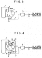
- an air duct 8 is connected to a boiler 1 into which the air for combustion preheated in an air preheater 4 is sent by a F.D.F. 9.
- Fuel is supplied through a burner (not shown) separated from the air duct 8.
- the exhaust gas resulting from combustion in the boiler 1 goes through an fuel economizer 6 and is denitrated in a denitration reactor 3. Then the exhaust gas is sent through an exhaust gas duct 7, the air preheater 4 and a dust collector 5 to the subsequent process by another F.D.F. 9.
- An ammonia supply apparatus 2 and a steam supply apparatus 16 are attached onto the above exhaust gas duct 7 at an upstream position of the denitration reactor 3.
- a denitration upstream damper 22 is disposed in the further upstream of these two apparatus.
- a denitration downstream damper 23 can be disposed in the exhaust gas duct in a downstream position of the denitration reactor 3 if necessary.
- a cool air supply device 19 is connected to the exhaust gas duct 7 at a position upstream from the denitration reactor 3 and downstream from the denitration upstream damper 22.
- this cool air supply device 19 may be a duct that branches out from the air duct 8 connected to the F.D.F. 9.
- the duct in this case (namely, the cool air supply device 19) has to have a cool air damper 21 so that this duct can be closed completely. Nevertheless it should be obvious that the air can also be sent into the system by a fan through a completely different route from the means shown in FIG. 4.
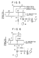
- the ammonia supply apparatus (nozzle) 2 is conventionally disposed in the exhaust gas duct 7 at an upstream position of the denitration reactor 3 (shown schematically).
- the steam supply apparatus 16 (whose nozzle is indicated by 16′) having a valve 17 is disposed according to the present invention.
- This steam supply apparatus 16 is essentially a tube that passes steam and can be almost anything if it has injection holes or nozzles or the like inside the exhaust gas duct 7.
- the cool air supply device 19 is a similar duct as the exhaust gas duct 7. This cool air supply device 19 only needs to be connected to this duct 7 and to have the cool air damper 21 so that the exhaust gas or cool air can be cut off. In the upstream of these, the denitration upstream damper 22 is disposed.
- the ammonia supply apparatus 2 in this embodiment comprises an ammonia tank 10, an ammonia vaporizer 11, an accumulator 12, a valve 13, a dilution fan 14, a dilution device 15 and an injection tube 18.
- Ammonia sent from the ammonia tank 10 through the ammonia vaporizer 11 and the accumulator 12 is diluted in the dilution device 15 with the air sent by the dilution fan 14 and injected into the duct 7 by the ammonia supply apparatus 2 via the injection tube 18.
- the steam supply apparatus 16 of FIG. 5 and the ammonia supply apparatus 2 may be unified as shown in FIG. 6. Namely, the steam supply apparatus 16 is connected to the injection tube 18 of the ammonia supply apparatus 2 described in FIG. 2. When ammonia is not being injected, the valve 17 can be opened so that steam is injected into the duct 7 through the nozzle of the ammonia supply apparatus 2. Further, according to this embodiment the cool air supply device 19 may also be omitted. In such a case, when ammonia is not being injected; namely, while the valve 13 is closed, the valve 17 is also closed and cool air can be supplied into the duct 7 by the dilution fan 14.
- steam and cool air may be supplied at the same time by the steam and cool air supply apparatuses 16, 19. Then, the denitration downstream damper 23 is closed, and either of steam and cool air can be supplied intermittently or continuously to maintain the temperature of the denitration reactor 3 at 100°C or less and the relative humidity at 40% or more.
- the denitration upstream damper 22 is closed immediately after the boiler 1 halts. Then the injection of ammonia and steam is stopped (namely, the valves 13, 17 are closed) as explained in connection with FIG. 6. Cool air is supplied using the ammonia supply apparatus 2, and the denitration downstream damper 23 is closed so that the atmosphere in the denitration reactor has a low temperature equal to or less than 100°C.
- the valve 17 is opened to supply steam using the same ammonia supply apparatus 2. This valve 17 is opened and closed intermittently so as to maintain the temperature at 100°C or less and the relative humidity at 40% or more.
- Denitrating catalyst A catalyst formed by clay and containing 80-85 weight % of a mixture of a carrier TiO2 (89-90 weight %), V2O5 (1 weight %) and WO3 (the rest).
- Composition of exhaust gas: O2 : 4% NOx : 1,000ppm SOx : 1,500ppm Dust: 30x103mg/Nm3 Arsenic Compounds (as As): 100-1,000 ⁇ g/Nm3 Attached dust was removed from the denitrating catalyst after about 600 hours of treatment, and then steam was supplied into the denitration reactor to vary the relative humidity of the atmosphere in the reactor. The recovery of performance was measured as follows. (The experimental condition for comparing catalytic (denitration) performance was: The gas composition was the same as above, the gas temperature 380°C and NH3/NOx 1.0.)
- the catalyst treated under the same condition as in Embodiment 1 was experimented at the relative humidities of 30%, 60%, and 80% after dust attached to the catalyst was sufficiently removed.
- the temperature of atmosphere in the reactor was maintained at 80°C. The results of recovery of performance thus measured are shown below.
- An exhaust gas of 380°C containing an arsenic component was treated by the same catalyst as in Embodiment 1 at the exhaust gas flow speed of about 5 m/sec. (at the entrance to the catalyst layer).
- the composition of the exhaust gas was: O2 : 4-5% NOx : 500-700ppm SOx : 800-1,000ppm Dust : 15-20g/Nm3 Arsenic Component: 100-300 ⁇ g/Nm3 (as As) Dust was sufficiently removed from the catalyst after the above treatment, and recovery of catalytic performance was observed at varying temperatures and humidities. The results are as shown below.
- the problem of degradation of denitration catalysts often encountered in the process of dry denitration of exhaust gas containing arsenic compounds, can be solved. It is now possible to continue a stable denitration treatment for a long period of time without replacing denitrating catalysts even when exhaust gas contains an arsenic component.
Landscapes
- Chemical & Material Sciences (AREA)
- Engineering & Computer Science (AREA)
- Chemical Kinetics & Catalysis (AREA)
- Environmental & Geological Engineering (AREA)
- Health & Medical Sciences (AREA)
- Organic Chemistry (AREA)
- Materials Engineering (AREA)
- Biomedical Technology (AREA)
- Analytical Chemistry (AREA)
- General Chemical & Material Sciences (AREA)
- Oil, Petroleum & Natural Gas (AREA)
- Exhaust Gas Treatment By Means Of Catalyst (AREA)
- Physical Or Chemical Processes And Apparatus (AREA)
Applications Claiming Priority (4)
| Application Number | Priority Date | Filing Date | Title |
|---|---|---|---|
| JP201878/87 | 1987-08-14 | ||
| JP20187887 | 1987-08-14 | ||
| JP244135/87 | 1987-09-30 | ||
| JP62244135A JPH01139146A (ja) | 1987-08-14 | 1987-09-30 | 砒素分による劣化脱硝触媒の再生方法及び同装置 |
Publications (2)
| Publication Number | Publication Date |
|---|---|
| EP0303560A1 EP0303560A1 (en) | 1989-02-15 |
| EP0303560B1 true EP0303560B1 (en) | 1993-07-14 |
Family
ID=26513050
Family Applications (1)
| Application Number | Title | Priority Date | Filing Date |
|---|---|---|---|
| EP88730176A Expired - Lifetime EP0303560B1 (en) | 1987-08-14 | 1988-08-08 | Method for denitration of exhaust gas containing arsenic compounds by catalysts and method and apparatus for regeneration of catalysts for denitration degraded by arsenic compounds |
Country Status (6)
| Country | Link |
|---|---|
| US (1) | US4925640A (da) |
| EP (1) | EP0303560B1 (da) |
| JP (1) | JPH01139146A (da) |
| DE (1) | DE3882300T2 (da) |
| DK (1) | DK171014B1 (da) |
| NO (1) | NO170318C (da) |
Families Citing this family (13)
| Publication number | Priority date | Publication date | Assignee | Title |
|---|---|---|---|---|
| KR960011040B1 (ko) * | 1992-03-24 | 1996-08-16 | 안자이 구니오 | 질소 산화물 제거방법과 그 실시에 사용하기 위한 장치 |
| DE19617081C2 (de) * | 1996-04-29 | 2003-02-06 | Kerr Mcgee Pigments Gmbh & Co | Verfahren zur Herstellung von Mischoxidpulvern aus desaktivierten DENOX-Katalysatoren |
| JPH1024219A (ja) * | 1996-07-11 | 1998-01-27 | Mitsubishi Heavy Ind Ltd | 排ガス脱硝方法 |
| EP1339479B1 (en) * | 2000-12-01 | 2007-03-07 | Fuel Tech, Inc. | SELECTIVE CATALYTIC REDUCTION OF NOx, ENABLED BY SIDE STREAM UREA DECOMPOSITION |
| US7829033B2 (en) * | 2003-07-03 | 2010-11-09 | Fuel Tech, Inc. | Selective catalytic reduction of NOx enabled by sidestream urea decomposition |
| JP2002372233A (ja) * | 2001-06-14 | 2002-12-26 | Seiji Inoue | ボイラ付帯設備 |
| JP3935417B2 (ja) * | 2002-11-01 | 2007-06-20 | 中国電力株式会社 | 脱硝触媒管理方法および脱硝触媒管理装置 |
| DE102006007658A1 (de) | 2006-02-18 | 2007-08-23 | Daimlerchrysler Ag | Dosiervorrichtung und Verfahren zum Betrieb derselben |
| JP5716188B2 (ja) | 2011-03-29 | 2015-05-13 | 三菱日立パワーシステムズ株式会社 | 砒素化合物の除去方法および除去装置、並びに脱硝触媒の再生方法および再生装置 |
| US10634029B2 (en) * | 2016-08-23 | 2020-04-28 | General Electric Technology Gmbh | Mobile selective catalyst reduction system |
| US20180058698A1 (en) * | 2016-08-23 | 2018-03-01 | General Electric Technology Gmbh | Tempered Ammonia Injection For Gas Turbine Selective Catalyst Reduction System |
| WO2018055165A1 (en) * | 2016-09-26 | 2018-03-29 | Shell Internationale Research Maatschappij B.V. | Method of regenerating a denox catalyst |
| KR20190050992A (ko) | 2016-09-26 | 2019-05-14 | 쉘 인터내셔날 리써취 마트샤피지 비.브이. | 산화질소 화합물 저감 방법 |
Family Cites Families (3)
| Publication number | Priority date | Publication date | Assignee | Title |
|---|---|---|---|---|
| DE2235426C3 (de) * | 1972-07-19 | 1975-01-02 | Sumitomo Chemical Co., Ltd., Osaka (Japan) | Verfahren zur Behandlung von Stickoxiden enthaltenden Abgasen |
| JPS592768B2 (ja) * | 1976-02-10 | 1984-01-20 | 株式会社日立製作所 | ガスタ−ビンの排ガス処理方法及びその装置 |
| JPS6048147A (ja) * | 1983-08-25 | 1985-03-15 | Mitsubishi Heavy Ind Ltd | 触媒の賦活方法 |
-
1987
- 1987-09-30 JP JP62244135A patent/JPH01139146A/ja active Pending
-
1988
- 1988-07-20 DK DK404888A patent/DK171014B1/da not_active IP Right Cessation
- 1988-07-22 NO NO883289A patent/NO170318C/no unknown
- 1988-08-08 EP EP88730176A patent/EP0303560B1/en not_active Expired - Lifetime
- 1988-08-08 DE DE88730176T patent/DE3882300T2/de not_active Expired - Fee Related
- 1988-08-15 US US07/232,610 patent/US4925640A/en not_active Expired - Fee Related
Also Published As
| Publication number | Publication date |
|---|---|
| DK404888D0 (da) | 1988-07-20 |
| NO883289D0 (no) | 1988-07-22 |
| US4925640A (en) | 1990-05-15 |
| DE3882300D1 (de) | 1993-08-19 |
| JPH01139146A (ja) | 1989-05-31 |
| NO883289L (no) | 1989-02-15 |
| DK171014B1 (da) | 1996-04-22 |
| NO170318B (no) | 1992-06-29 |
| DK404888A (da) | 1989-02-15 |
| EP0303560A1 (en) | 1989-02-15 |
| DE3882300T2 (de) | 1993-10-21 |
| NO170318C (no) | 1992-10-07 |
Similar Documents
| Publication | Publication Date | Title |
|---|---|---|
| EP0303560B1 (en) | Method for denitration of exhaust gas containing arsenic compounds by catalysts and method and apparatus for regeneration of catalysts for denitration degraded by arsenic compounds | |
| EP2321035B1 (en) | A method and a device for removing nitrogen oxides and sulphur trioxide from a process gas | |
| JP4175465B2 (ja) | 排ガス中の水銀除去方法およびそのシステム | |
| US6528030B2 (en) | Alkaline sorbent injection for mercury control | |
| US6117405A (en) | Process for removing nitrogen oxides from flue gases | |
| KR100629645B1 (ko) | 배출물을 처리하기 위한 방법 | |
| JP5121637B2 (ja) | 脱硝触媒の再生方法、脱硝触媒の再生装置およびこれを用いた排ガス処理装置 | |
| EP0136966B1 (en) | Method for reactivating catalysts | |
| KR102887730B1 (ko) | 병렬된 연도가스 처리 시스템의 비활성화된 scr 촉매를 재생하기 위한, 선택적 촉매 환원 공정 및 방법 | |
| US5283052A (en) | Apparatus for regenerating depleted deNOx catalysts | |
| KR102915067B1 (ko) | 선택적 촉매 환원 공정 및 상기 공정의 비활성화된 촉매를 재생하는 방법 | |
| EP0567964A2 (en) | Process for flue gas denitration | |
| KR102150227B1 (ko) | 암모니아 분사장치를 삽입한 촉매 일체형 집진기 | |
| CN114950120B (zh) | 一种硫回收尾气除尘脱硫脱硝一体化系统及方法 | |
| KR19990050193A (ko) | 연소배가스의 대기오염물질 연속처리방법 및 이에 이용되는 장치 | |
| EP2561920A1 (en) | Method and system for NOx reduction in flue gas | |
| JPH07204433A (ja) | 排ガスの浄化処理方法およびその装置 | |
| JPS6344925A (ja) | 排気ガスの脱硝処理方法 | |
| EP3036480B1 (en) | Arrangement and method for flue gas stream bypass during selective catalytic reduction | |
| EP0679427A1 (en) | Exhaust gas cleaner | |
| JPH1114034A (ja) | 排ガス処理装置およびその運転方法 | |
| EP0468205B1 (en) | Apparatus for treating exhaust gas | |
| KR20240015266A (ko) | 소각로 및 연소로의 배출가스 처리장치 | |
| JPH09155123A (ja) | 排ガス処理用バグフィルタ及びその運転方法 | |
| JPH08257363A (ja) | 排ガスの処理方法 |
Legal Events
| Date | Code | Title | Description |
|---|---|---|---|
| PUAI | Public reference made under article 153(3) epc to a published international application that has entered the european phase |
Free format text: ORIGINAL CODE: 0009012 |
|
| AK | Designated contracting states |
Kind code of ref document: A1 Designated state(s): DE GB IT NL |
|
| 17P | Request for examination filed |
Effective date: 19890310 |
|
| 17Q | First examination report despatched |
Effective date: 19910319 |
|
| GRAA | (expected) grant |
Free format text: ORIGINAL CODE: 0009210 |
|
| ITF | It: translation for a ep patent filed | ||
| AK | Designated contracting states |
Kind code of ref document: B1 Designated state(s): DE GB IT NL |
|
| REF | Corresponds to: |
Ref document number: 3882300 Country of ref document: DE Date of ref document: 19930819 |
|
| PLBE | No opposition filed within time limit |
Free format text: ORIGINAL CODE: 0009261 |
|
| STAA | Information on the status of an ep patent application or granted ep patent |
Free format text: STATUS: NO OPPOSITION FILED WITHIN TIME LIMIT |
|
| 26N | No opposition filed | ||
| PGFP | Annual fee paid to national office [announced via postgrant information from national office to epo] |
Ref country code: DE Payment date: 19940816 Year of fee payment: 7 |
|
| PGFP | Annual fee paid to national office [announced via postgrant information from national office to epo] |
Ref country code: GB Payment date: 19940826 Year of fee payment: 7 |
|
| PGFP | Annual fee paid to national office [announced via postgrant information from national office to epo] |
Ref country code: NL Payment date: 19940831 Year of fee payment: 7 |
|
| PG25 | Lapsed in a contracting state [announced via postgrant information from national office to epo] |
Ref country code: GB Effective date: 19950808 |
|
| PG25 | Lapsed in a contracting state [announced via postgrant information from national office to epo] |
Ref country code: NL Effective date: 19960301 |
|
| GBPC | Gb: european patent ceased through non-payment of renewal fee |
Effective date: 19950808 |
|
| NLV4 | Nl: lapsed or anulled due to non-payment of the annual fee |
Effective date: 19960301 |
|
| PG25 | Lapsed in a contracting state [announced via postgrant information from national office to epo] |
Ref country code: DE Effective date: 19960501 |
|
| PG25 | Lapsed in a contracting state [announced via postgrant information from national office to epo] |
Ref country code: IT Free format text: LAPSE BECAUSE OF NON-PAYMENT OF DUE FEES Effective date: 20050808 |