EP0303589A2 - Injecteur de combustible avec capteur de levée d'aiguille - Google Patents
Injecteur de combustible avec capteur de levée d'aiguille Download PDFInfo
- Publication number
- EP0303589A2 EP0303589A2 EP88890199A EP88890199A EP0303589A2 EP 0303589 A2 EP0303589 A2 EP 0303589A2 EP 88890199 A EP88890199 A EP 88890199A EP 88890199 A EP88890199 A EP 88890199A EP 0303589 A2 EP0303589 A2 EP 0303589A2
- Authority
- EP
- European Patent Office
- Prior art keywords
- intermediate plate
- coil
- fuel injection
- injection nozzle
- nozzle
- Prior art date
- Legal status (The legal status is an assumption and is not a legal conclusion. Google has not performed a legal analysis and makes no representation as to the accuracy of the status listed.)
- Withdrawn
Links
Images


Classifications
-
- F—MECHANICAL ENGINEERING; LIGHTING; HEATING; WEAPONS; BLASTING
- F02—COMBUSTION ENGINES; HOT-GAS OR COMBUSTION-PRODUCT ENGINE PLANTS
- F02M—SUPPLYING COMBUSTION ENGINES IN GENERAL WITH COMBUSTIBLE MIXTURES OR CONSTITUENTS THEREOF
- F02M65/00—Testing fuel-injection apparatus, e.g. testing injection timing ; Cleaning of fuel-injection apparatus
- F02M65/005—Measuring or detecting injection-valve lift, e.g. to determine injection timing
Definitions
- the invention relates to a fuel injector with a needle stroke sensor according to the preamble of claim 1.
- An injection nozzle of this type is known for example from DE-OS 29 32 480.
- the induction coil surrounds part of the pressure pin and part of the pressure pin of the nozzle needle, these parts forming the core of the coil.
- the pressure pin is moved a little out of the coil, which changes the reluctance of its magnetic circuit, which is magnetized either by a direct current flowing through the coil or by a permanent magnet.
- the change in reluctance leads to an induction signal from the coil which is representative of the needle movement and which can be supplied, for example, to an electronic control device for the internal combustion engine.
- a working air gap is additionally provided in the coil core, which is formed by a raised ring of the intermediate plate and the end face of the pressure bolt.
- Another working air gap can be formed outside the coil by an end face of an annular permanent magnet and the spring plate.
- the aim of the invention is to provide an injection nozzle which delivers a needle stroke signal which is sufficiently high for practical processing. Despite the prevailing unfavorable conditions, such as high temperatures and fuel atmosphere, a long service life and reliability should be given.
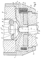
- Fig. 1 shows a first embodiment
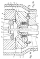
- Fig. 2 shows a second embodiment
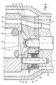
- Fig. 3a and 3b shows a third and fourth embodiment
- Fig. 4 shows a fifth and Fig. 5 a sixth embodiment.
- FIG. 1 shows the middle part of an injection nozzle, in which the features essential to the invention are contained.
- the invention is shown using the example of a diesel injection nozzle, in which the nozzle needle lifts off due to the pressure of the injected fuel, which may be a conventional nozzle or a pump nozzle.
- the injection nozzle has a nozzle body 1 with a central bearing bore 2 for a nozzle needle 3.
- the needle 3, which is displaceable along the nozzle axis a, is seated on a valve seat in a known manner, not shown here, with a sealing cone.
- an intermediate plate 4 which is a central Boh tion 5 has.
- a pressure pin 7 of the nozzle needle 3 runs in this bore 5, leaving a radial gap 6.
- the compression spring 10 With its lower end, the compression spring 10 rests on a spring plate 11, which rests on the pressure pin 7 of the nozzle needle 3 with a pressure bolt 12 arranged on its underside.
- the nozzle body 1, the intermediate plate 4 and the nozzle holder 8 are held together by a housing 13, which can be a union nut, for example. All four parts mentioned above are generally made of ferromagnetic steel.
- a fuel channel 14 which is in the form of bores from an upper connection, not shown, through the nozzle holder 8, the intermediate plate 4 and the nozzle body 1 to the valve seat of the needle, which cannot be seen in the drawing 3 extends.
- annular groove 15 open towards the bottom is formed.
- a coil 16 which is embedded in a coil holder 17 made of plastic, is inserted into this annular groove.
- the axis of the coil 16 coincides with the nozzle axis a.
- An electrical line (not shown) is led from the coil connections to the outside and at a suitable point through the housing 13 through a bore 18 which is only indicated by dashed lines. Accordingly, a substantially annular section 19 of the intermediate plate 4 remains between the bore 5 and the coil 16.
- a disk-shaped intermediate layer 20 made of non-ferromagnetic material, for example made of a wrought copper alloy or non-magnetic steel.
- This intermediate layer 20 extends from the inner surface of a ferromagnetic peripheral Ring 21 up to the outer surface of the annular section 19.
- annular recess 22 extending from the bearing bore 2 is provided in the end face of the nozzle body 1 facing the intermediate plate 4.
- the ring 21, which serves as a guide piece for the magnetic flux of the coil 16, can be fixed in a manner not shown, for example by pins fitted into radial bores of the nozzle body 1.
- nozzle needle 2 is drawn in its closed position, in which it is pressed against its valve seat by the compression spring 10 via the spring plate 11, the pressure pin 12 and the pressure pin 6.
- the coil 16 can be stored with a constant direct current via the leads, not shown.
- a magnetic field arises, the essential course of which is shown by a representative field line b in FIG. 1.
- the field lines run over the section 19 of the intermediate plate 4, over the working air gap 1, which lies between the end face of the section 19 and the end face of that projecting annular shoulder 23, which lies between the circumference of the nozzle needle 2 and the circumference of the pressure pin 7, further over the Nozzle needle 3, the nozzle body 1, the peripheral ring 21 and via the intermediate plate 4 again in the section 19.
- the nozzle needle 3 rises until it finally lies in the fully open position with the annular shoulder 23 on the end face of the section 19.
- the working air gap 1 thus changes during the opening movement of the needle 2 from a length that corresponds to the maximum needle stroke to zero length. This change causes a large increase in the reluctance of the magnet Circle of the coil 16, whereby a signal is induced in the coil 16, which can be supplied as a needle stroke signal to an electronic control device for the internal combustion engine.
- the premagnetization by means of a constant direct current can be omitted if one provides for the premagnetization of the magnetic circuit described above by means of a permanent magnet.
- a disk-shaped permanent magnet 24 is placed on an upper extension 25 of the spring plate 11 and here sprayed on Plastic cap 26 held. A part of the flux of the permanent magnet 24 also runs in the magnetic circuit which is decisive for the coil 16, so that the described change in the working air gap 1 causes an induction signal which can be easily evaluated.
- a permanent magnet can also be arranged elsewhere in the nozzle, provided that the magnetic circuit determining the coil 16 is sufficiently pre-magnetized.
- the ring 21 can be designed as a magnet.
- several magnets can be used, or the permanent magnet can be provided in or on the intermediate plate 4.
- FIG. 2 essentially corresponds to that shown in FIG. 1 and the same reference numerals are used for the same parts, which also applies to the figures that follow.
- the coil 16 with its coil holder 17 is inserted here into a circumferential groove 27 of the intermediate plate 4 and a disc-shaped insert 28 made of non-ferromagnetic material is arranged in a recess of the intermediate plate 4 facing the nozzle body 1 and extends from the coil 16 to the recess 22 , which connects to the working air gap 1, extends.
- the flux essentially runs outside via the housing 13.
- a permanent magnet can be provided at a suitable point. The function is the same as described in connection with FIG. 1.
- the coil 16 is seated with a coil holder 17 as in FIG. 1 in an annular groove 15 of the intermediate plate 4.
- the annular groove 15 is not covered here by an intermediate layer towards the recess 22.
- centering pins 29, which are inserted into corresponding blind bores of the intermediate plate 4 or of the nozzle body 1 and are made, for example, of steel, are used primarily for returning the flow.
- These centering pins 29 also serve to center the intermediate plate 4 with respect to the nozzle body 1 at the correct angle.
- Centering pins can also be provided for centering the plate 4 with respect to the nozzle holder 8. The correct angular centering is necessary primarily because of the fuel channel 14 (see FIG. 1), since the corresponding holes have to merge into one another.
- the course of the river is indicated by a field line b.
- FIG. 3b differs from that of FIG. 3a in that - as in FIG. 1 - an intermediate layer 20 made of non-ferromagnetic material is provided.
- annular groove 15 and the coil holder 16 are designed somewhat differently.
- the embodiment according to FIG. 4 differs from the previously described embodiments primarily in that the coil 30 does not run concentrically to the nozzle axis a, but is offset radially outward.
- the coil 30 together with a coil body 31 is inserted into a recess 32 of the intermediate plate 4 which is open towards the edge.
- a core pin 33 made of ferromagnetic material runs from the intermediate plate 4 through the center of the coil into the nozzle body 1.
- the axis of the core pin 33 coincides with the coil axis s.
- the core pin 33 sits with a press fit in a corresponding hole in the intermediate plate and engages with as little play as possible in a hole in the nozzle body 1.
- a disk-shaped insert 34 made of non-ferromagnetic material is inserted into a recess in the intermediate plate 4, similarly to the embodiment according to FIG. 2.
- the connecting wires of the coil 30 are connected to contact pins 35 which lead into the space between housing 13 and intermediate plate 4. From here, a line, not shown, can lead out of the housing 13.
- a field line b representative of the relevant river course is shown in broken lines. In this embodiment, too, which is not rotationally symmetrical with respect to the nozzle axis a, the function is the same as that discussed in connection with the other embodiments. If, in addition to the core pin 33, dowel pins are used to center the intermediate plate 4, such dowel pins should be made of non-ferromagnetic material in order to avoid unwanted magnetic shunts.
- a special coil former 36 made of non-magnetizable steel is provided.
- This coil former 36 has a sleeve part 37 which surrounds the annular section 19 of the intermediate plate 4 and which at its upper end merges into a short collar 38 which is bent obliquely upwards and outwards, but at its lower end into an annular flange 39.
- This ring flange 39 lies in the manner shown between the intermediate plate 4 and the nozzle body 1, whereby it has the function of the intermediate layer 20 described in connection with FIG. 1.
- the coil body 36 receives the coil 16, which has, for example, a trapezoidal angular cross section, so that it is covered on three sides by the body 36.
- a radial recess 40 extends from the annular groove 15, into which the coil former 36 together with the coil 16 can be inserted, which can be seen on the left-hand side of FIG. 5.
- the connecting cables 41 of the coil 16 are immovably pressed against the flange 39 of the coil body 36 by means of a holding block 42 and a rivet 43.
- the remaining cavities, in particular also the annular outer space between the coil 16 and the intermediate plate 4 are covered with a cast resin layer 42 or the like. poured out.
- the described embodiment of the coil body 36 brings not only the advantage of a reduction in the number of individual parts (due to the omission of the intermediate layer 20 according to FIG. 1), but also a particularly stable mounting of the coil, which is also protected against the strong squeezing flow that occurs when opening the nozzle needle occurs when the fuel located between the end face of the annular section 19 and the annular shoulder 23 of the nozzle needle 3 is suddenly displaced.
- a ring 21 as shown in FIG. 1 or centering pins 29 as shown in FIGS. 3a or 3b are expediently provided as guide pieces for the magnetic flux.
Landscapes
- Engineering & Computer Science (AREA)
- Chemical & Material Sciences (AREA)
- Combustion & Propulsion (AREA)
- Mechanical Engineering (AREA)
- General Engineering & Computer Science (AREA)
- Fuel-Injection Apparatus (AREA)
Applications Claiming Priority (2)
| Application Number | Priority Date | Filing Date | Title |
|---|---|---|---|
| DE19873726712 DE3726712A1 (de) | 1987-08-11 | 1987-08-11 | Kraftstoff-einspritzduese mit nadelhubsensor |
| DE3726712 | 1987-08-11 |
Publications (2)
| Publication Number | Publication Date |
|---|---|
| EP0303589A2 true EP0303589A2 (fr) | 1989-02-15 |
| EP0303589A3 EP0303589A3 (fr) | 1990-01-31 |
Family
ID=6333526
Family Applications (1)
| Application Number | Title | Priority Date | Filing Date |
|---|---|---|---|
| EP88890199A Withdrawn EP0303589A3 (fr) | 1987-08-11 | 1988-07-28 | Injecteur de combustible avec capteur de levée d'aiguille |
Country Status (2)
| Country | Link |
|---|---|
| EP (1) | EP0303589A3 (fr) |
| DE (1) | DE3726712A1 (fr) |
Cited By (5)
| Publication number | Priority date | Publication date | Assignee | Title |
|---|---|---|---|---|
| GB2260165A (en) * | 1991-10-01 | 1993-04-07 | Lucas Ind Plc | I.c. engine fuel injector |
| DE4325904A1 (de) * | 1993-08-02 | 1995-02-09 | Daimler Benz Ag | Für eine Dieselbrennkraftmaschine vorgesehene Kraftstoffeinspritzanlage mit einer den Kraftstoff fördernden Hochdruckpumpe in eine gemeinsame Versorgungsleitung (Common-Rail) für alle Einspritzdüsen |
| DE4108416C2 (de) * | 1991-03-15 | 2000-05-18 | Bosch Gmbh Robert | Kraftstoff-Einspritzdüse für Brennkraftmaschinen |
| EP1598544A2 (fr) * | 2003-03-06 | 2005-11-23 | Carl Freudenberg KG | Dispositif pour alimenter, notamment, le tuyau d'admission d'un moteur à combustion interne en quantités dosées de composants volatils de carburants d'un véhicule |
| WO2015039992A1 (fr) * | 2013-09-17 | 2015-03-26 | Robert Bosch Gmbh | Injecteur de carburant |
Families Citing this family (4)
| Publication number | Priority date | Publication date | Assignee | Title |
|---|---|---|---|---|
| DE3832101A1 (de) * | 1988-09-21 | 1990-03-22 | Voest Alpine Automotive | Verfahren und vorrichtung zur messung der kraftstofftemperatur bei einer elektronisch geregelten brennkraftmaschine |
| DE3841059C1 (fr) * | 1988-12-06 | 1990-05-23 | Voest-Alpine Automotive Ges.M.B.H., Linz, At | |
| DE102005019806B4 (de) * | 2005-04-28 | 2008-12-18 | Continental Automotive Gmbh | Einspritzventil für eine Brennkraftmaschine |
| DE102014216834A1 (de) | 2014-08-25 | 2016-02-25 | Robert Bosch Gmbh | Kraftstoffinjektor |
Family Cites Families (4)
| Publication number | Priority date | Publication date | Assignee | Title |
|---|---|---|---|---|
| DE2932480A1 (de) * | 1979-08-10 | 1981-02-26 | Bosch Gmbh Robert | Kraftstoff-einspritzduese fuer brennkraftmaschinen |
| DE3024424A1 (de) * | 1980-06-28 | 1982-01-21 | Robert Bosch Gmbh, 7000 Stuttgart | Kraftstoffeinspritzventil fuer brennkraftmaschinen |
| DE3125884A1 (de) * | 1981-07-01 | 1983-01-20 | Robert Bosch Gmbh, 7000 Stuttgart | Kraftstoff-einspritzduese fuer brennkraftmaschinen |
| DE3326840A1 (de) * | 1983-07-26 | 1985-02-14 | Robert Bosch Gmbh, 7000 Stuttgart | Kraftstoff-einspritzduese fuer brennkraftmaschinen |
-
1987
- 1987-08-11 DE DE19873726712 patent/DE3726712A1/de active Granted
-
1988
- 1988-07-28 EP EP88890199A patent/EP0303589A3/fr not_active Withdrawn
Cited By (6)
| Publication number | Priority date | Publication date | Assignee | Title |
|---|---|---|---|---|
| DE4108416C2 (de) * | 1991-03-15 | 2000-05-18 | Bosch Gmbh Robert | Kraftstoff-Einspritzdüse für Brennkraftmaschinen |
| GB2260165A (en) * | 1991-10-01 | 1993-04-07 | Lucas Ind Plc | I.c. engine fuel injector |
| DE4325904A1 (de) * | 1993-08-02 | 1995-02-09 | Daimler Benz Ag | Für eine Dieselbrennkraftmaschine vorgesehene Kraftstoffeinspritzanlage mit einer den Kraftstoff fördernden Hochdruckpumpe in eine gemeinsame Versorgungsleitung (Common-Rail) für alle Einspritzdüsen |
| US5479902A (en) * | 1993-08-02 | 1996-01-02 | Daimler-Benz Ag | Fuel injection system for a diesel engine |
| EP1598544A2 (fr) * | 2003-03-06 | 2005-11-23 | Carl Freudenberg KG | Dispositif pour alimenter, notamment, le tuyau d'admission d'un moteur à combustion interne en quantités dosées de composants volatils de carburants d'un véhicule |
| WO2015039992A1 (fr) * | 2013-09-17 | 2015-03-26 | Robert Bosch Gmbh | Injecteur de carburant |
Also Published As
| Publication number | Publication date |
|---|---|
| DE3726712A1 (de) | 1989-04-27 |
| DE3726712C2 (fr) | 1991-07-04 |
| EP0303589A3 (fr) | 1990-01-31 |
Similar Documents
| Publication | Publication Date | Title |
|---|---|---|
| EP0975868B1 (fr) | Soupape a commande electromagnetique | |
| EP0772738B1 (fr) | Soupape a commande electromagnetique | |
| EP0136594B1 (fr) | Electro-aimant | |
| EP0076459B1 (fr) | Soupape électromagnétique, notamment soupape d'injection de combustible | |
| DE3624218C2 (fr) | ||
| DE4310719C2 (de) | Verfahren zur Herstellung eines Magnetkreises für ein Ventil | |
| DE69700259T2 (de) | Elektromagnetische Vorrichtung mit Positionsregelung für Stator | |
| DE19744739A1 (de) | Brennstoffeinspritzventil | |
| WO2006005639A1 (fr) | Soupape d'injection de carburant | |
| EP1270930A1 (fr) | Vanne electromagnetique pour piloter un injecteur d'un moteur a combustion interne | |
| WO1996008647A1 (fr) | Procede de production d'un circuit magnetique pour soupape | |
| DE3834446A1 (de) | Elektromagnetisches einspritzventil in patronenbauweise | |
| DE69616448T2 (de) | Aufbau eines Magnetspaltes | |
| DE3618729A1 (de) | Elektromagnetische betaetigungsvorrichtung | |
| DE3726712C2 (fr) | ||
| DE3137761C2 (fr) | ||
| DE102008040168A1 (de) | Magnetventil für einen Kraftstoff-Injektor sowie Kraftstoff-Injektor | |
| DE68908423T2 (de) | Elektromagnetisches düsenklappenventil für kraftstoffeinspritzung in kraftfahrzeugen. | |
| EP0460125A1 (fr) | Soupape a commande electromagnetique. | |
| DE3500449A1 (de) | Magnetventil zur fluidsteuerung | |
| EP0099991B1 (fr) | Buse d'injection de carburant pour moteurs à combustion interne | |
| DE3703615A1 (de) | Kraftstoffeinspritzventil | |
| DE10235240B4 (de) | Magnetventilgesteuerte Einspritzdüse | |
| DE10300136A1 (de) | Kraftstoffeinspritzvorrichtung mit stationärem und bewegbarem Kern | |
| EP0068339A1 (fr) | Buse d'injection de carburant pour moteurs à combustion interne |
Legal Events
| Date | Code | Title | Description |
|---|---|---|---|
| PUAI | Public reference made under article 153(3) epc to a published international application that has entered the european phase |
Free format text: ORIGINAL CODE: 0009012 |
|
| AK | Designated contracting states |
Kind code of ref document: A2 Designated state(s): AT CH DE ES FR GB IT LI SE |
|
| PUAL | Search report despatched |
Free format text: ORIGINAL CODE: 0009013 |
|
| AK | Designated contracting states |
Kind code of ref document: A3 Designated state(s): AT CH DE ES FR GB IT LI SE |
|
| 17P | Request for examination filed |
Effective date: 19900329 |
|
| 17Q | First examination report despatched |
Effective date: 19910215 |
|
| RAP1 | Party data changed (applicant data changed or rights of an application transferred) |
Owner name: AUTOMOTIVE DIESEL GESELLSCHAFT M.B.H. |
|
| STAA | Information on the status of an ep patent application or granted ep patent |
Free format text: STATUS: THE APPLICATION IS DEEMED TO BE WITHDRAWN |
|
| 18D | Application deemed to be withdrawn |
Effective date: 19911220 |