EP0303591A2 - Procédé de traitement de matières dans une décharge, réservoir de mise à la décharge pour mettre en oeuvre ledit procédé et toit amovible pour ledit réservoir - Google Patents
Procédé de traitement de matières dans une décharge, réservoir de mise à la décharge pour mettre en oeuvre ledit procédé et toit amovible pour ledit réservoir Download PDFInfo
- Publication number
- EP0303591A2 EP0303591A2 EP88890204A EP88890204A EP0303591A2 EP 0303591 A2 EP0303591 A2 EP 0303591A2 EP 88890204 A EP88890204 A EP 88890204A EP 88890204 A EP88890204 A EP 88890204A EP 0303591 A2 EP0303591 A2 EP 0303591A2
- Authority
- EP
- European Patent Office
- Prior art keywords
- filter layer
- layer
- landfill
- surface filter
- container
- Prior art date
- Legal status (The legal status is an assumption and is not a legal conclusion. Google has not performed a legal analysis and makes no representation as to the accuracy of the status listed.)
- Withdrawn
Links
- 239000000463 material Substances 0.000 title claims abstract description 57
- 238000000034 method Methods 0.000 title claims abstract description 24
- 238000007789 sealing Methods 0.000 claims abstract description 79
- 239000007788 liquid Substances 0.000 claims abstract description 38
- 229910052500 inorganic mineral Inorganic materials 0.000 claims abstract description 33
- 239000011707 mineral Substances 0.000 claims abstract description 33
- 239000007789 gas Substances 0.000 claims abstract description 19
- 238000003860 storage Methods 0.000 claims abstract description 4
- 230000007774 longterm Effects 0.000 claims abstract description 3
- 230000000284 resting effect Effects 0.000 claims abstract description 3
- 239000010410 layer Substances 0.000 claims description 132
- 239000004033 plastic Substances 0.000 claims description 10
- 229920003023 plastic Polymers 0.000 claims description 10
- 239000004567 concrete Substances 0.000 claims description 9
- 239000011241 protective layer Substances 0.000 claims description 9
- 239000002734 clay mineral Substances 0.000 claims description 6
- 238000009792 diffusion process Methods 0.000 claims description 5
- 230000007704 transition Effects 0.000 claims description 5
- RYGMFSIKBFXOCR-UHFFFAOYSA-N Copper Chemical compound [Cu] RYGMFSIKBFXOCR-UHFFFAOYSA-N 0.000 claims description 4
- 229910000831 Steel Inorganic materials 0.000 claims description 4
- 238000004140 cleaning Methods 0.000 claims description 4
- 229920006262 high density polyethylene film Polymers 0.000 claims description 4
- 239000010959 steel Substances 0.000 claims description 4
- 229910052802 copper Inorganic materials 0.000 claims description 3
- 239000010949 copper Substances 0.000 claims description 3
- 239000013013 elastic material Substances 0.000 claims description 2
- 238000011068 loading method Methods 0.000 claims description 2
- 238000009434 installation Methods 0.000 claims 1
- 238000007689 inspection Methods 0.000 description 12
- 238000011049 filling Methods 0.000 description 9
- XLYOFNOQVPJJNP-UHFFFAOYSA-N water Substances O XLYOFNOQVPJJNP-UHFFFAOYSA-N 0.000 description 7
- 239000002699 waste material Substances 0.000 description 6
- MHAJPDPJQMAIIY-UHFFFAOYSA-N Hydrogen peroxide Chemical compound OO MHAJPDPJQMAIIY-UHFFFAOYSA-N 0.000 description 4
- 238000002347 injection Methods 0.000 description 4
- 239000007924 injection Substances 0.000 description 4
- 229910052751 metal Inorganic materials 0.000 description 4
- 239000002184 metal Substances 0.000 description 4
- 239000000126 substance Substances 0.000 description 4
- 238000006243 chemical reaction Methods 0.000 description 3
- 238000004181 pedogenesis Methods 0.000 description 3
- 230000002093 peripheral effect Effects 0.000 description 3
- 238000010926 purge Methods 0.000 description 3
- 239000000565 sealant Substances 0.000 description 3
- 239000002689 soil Substances 0.000 description 3
- 239000004568 cement Substances 0.000 description 2
- 239000007795 chemical reaction product Substances 0.000 description 2
- 239000000470 constituent Substances 0.000 description 2
- 238000005260 corrosion Methods 0.000 description 2
- 230000007797 corrosion Effects 0.000 description 2
- 239000003344 environmental pollutant Substances 0.000 description 2
- 230000002349 favourable effect Effects 0.000 description 2
- 238000011010 flushing procedure Methods 0.000 description 2
- 239000003673 groundwater Substances 0.000 description 2
- 238000002386 leaching Methods 0.000 description 2
- 231100000719 pollutant Toxicity 0.000 description 2
- 229920000642 polymer Polymers 0.000 description 2
- 239000000047 product Substances 0.000 description 2
- 230000001681 protective effect Effects 0.000 description 2
- 239000010802 sludge Substances 0.000 description 2
- 239000007787 solid Substances 0.000 description 2
- 239000000243 solution Substances 0.000 description 2
- 239000002352 surface water Substances 0.000 description 2
- 235000008645 Chenopodium bonus henricus Nutrition 0.000 description 1
- 244000138502 Chenopodium bonus henricus Species 0.000 description 1
- 244000007645 Citrus mitis Species 0.000 description 1
- 229910052782 aluminium Inorganic materials 0.000 description 1
- XAGFODPZIPBFFR-UHFFFAOYSA-N aluminium Chemical compound [Al] XAGFODPZIPBFFR-UHFFFAOYSA-N 0.000 description 1
- 238000013459 approach Methods 0.000 description 1
- 239000010426 asphalt Substances 0.000 description 1
- 230000004888 barrier function Effects 0.000 description 1
- 239000011230 binding agent Substances 0.000 description 1
- 239000006227 byproduct Substances 0.000 description 1
- 238000010668 complexation reaction Methods 0.000 description 1
- 150000001875 compounds Chemical class 0.000 description 1
- 238000007596 consolidation process Methods 0.000 description 1
- 238000010276 construction Methods 0.000 description 1
- 238000010924 continuous production Methods 0.000 description 1
- 238000013461 design Methods 0.000 description 1
- 238000001514 detection method Methods 0.000 description 1
- 238000000502 dialysis Methods 0.000 description 1
- VTIIJXUACCWYHX-UHFFFAOYSA-L disodium;carboxylatooxy carbonate Chemical compound [Na+].[Na+].[O-]C(=O)OOC([O-])=O VTIIJXUACCWYHX-UHFFFAOYSA-L 0.000 description 1
- 239000003792 electrolyte Substances 0.000 description 1
- 238000001962 electrophoresis Methods 0.000 description 1
- 230000007613 environmental effect Effects 0.000 description 1
- 230000005284 excitation Effects 0.000 description 1
- 238000004880 explosion Methods 0.000 description 1
- 238000000605 extraction Methods 0.000 description 1
- 239000003337 fertilizer Substances 0.000 description 1
- 239000012530 fluid Substances 0.000 description 1
- 239000011888 foil Substances 0.000 description 1
- 239000002920 hazardous waste Substances 0.000 description 1
- 239000003864 humus Substances 0.000 description 1
- 230000003993 interaction Effects 0.000 description 1
- 238000005342 ion exchange Methods 0.000 description 1
- 230000004807 localization Effects 0.000 description 1
- 238000002156 mixing Methods 0.000 description 1
- 239000010815 organic waste Substances 0.000 description 1
- 230000003647 oxidation Effects 0.000 description 1
- 238000007254 oxidation reaction Methods 0.000 description 1
- 238000012856 packing Methods 0.000 description 1
- 239000003973 paint Substances 0.000 description 1
- 239000002985 plastic film Substances 0.000 description 1
- 229920006255 plastic film Polymers 0.000 description 1
- 239000000843 powder Substances 0.000 description 1
- 238000001556 precipitation Methods 0.000 description 1
- 238000003672 processing method Methods 0.000 description 1
- 239000011150 reinforced concrete Substances 0.000 description 1
- 239000008237 rinsing water Substances 0.000 description 1
- 239000002002 slurry Substances 0.000 description 1
- 229960001922 sodium perborate Drugs 0.000 description 1
- 229940045872 sodium percarbonate Drugs 0.000 description 1
- YKLJGMBLPUQQOI-UHFFFAOYSA-M sodium;oxidooxy(oxo)borane Chemical compound [Na+].[O-]OB=O YKLJGMBLPUQQOI-UHFFFAOYSA-M 0.000 description 1
- 239000012265 solid product Substances 0.000 description 1
- 239000004575 stone Substances 0.000 description 1
- 229910052572 stoneware Inorganic materials 0.000 description 1
- 238000009423 ventilation Methods 0.000 description 1
- 238000004065 wastewater treatment Methods 0.000 description 1
Images

Classifications
-
- E—FIXED CONSTRUCTIONS
- E02—HYDRAULIC ENGINEERING; FOUNDATIONS; SOIL SHIFTING
- E02D—FOUNDATIONS; EXCAVATIONS; EMBANKMENTS; UNDERGROUND OR UNDERWATER STRUCTURES
- E02D31/00—Protective arrangements for foundations or foundation structures; Ground foundation measures for protecting the soil or the subsoil water, e.g. preventing or counteracting oil pollution
- E02D31/002—Ground foundation measures for protecting the soil or subsoil water, e.g. preventing or counteracting oil pollution
- E02D31/004—Sealing liners
-
- B—PERFORMING OPERATIONS; TRANSPORTING
- B09—DISPOSAL OF SOLID WASTE; RECLAMATION OF CONTAMINATED SOIL
- B09B—DISPOSAL OF SOLID WASTE NOT OTHERWISE PROVIDED FOR
- B09B1/00—Dumping solid waste
Definitions
- the invention relates to a method for treating landfill material, a special landfill container, in particular for carrying out this method, and a particularly removable roof with material feeder and circular conveyor, also for landfill containers.
- landfill materials of different origins should not be stored indiscriminately, but separately, since many uncontrollable reactions between the different fractions can occur over long periods of time. As is well known, this is difficult; the possibilities are rarely available.
- the aim is to achieve a stable landfill status, in which no changes in the landfill material occur, and experience has already shown that with various mixed landfill materials, this state will not be reached even after a few decades, so that leachate control and disposal are necessary over these long periods would be, but is not carried out in many cases.
- AT-PS 372 308 describes a process for removing oily, water-immiscible waste by adsorbing it on a solid substance (e.g. lime powder) and mixing it with a liquid environmentally hazardous waste material to form an aqueous slurry, which after adding cement to a solid stone stiffens.
- a solid substance e.g. lime powder
- a similar consolidation by adding cement is in ZP-A 0 104 773 for liquid and semi-liquid organic waste materials, e.g. of activated sludge and primary sludge from wastewater treatment plants.
- the solid product obtained is stored as such as open landfill or used in ground form as a fertilizer.
- EP-A 0 185 831 describes a continuous process in which the floor is slurried with rinsing water and thereby extracted. The mud goes back on site; the polluted rinse water goes to water treatment.
- EP-A 0 059 020 sealing walls are sunk all the way around the contaminated floor layer to a liquid-tight floor layer and floor lances carrying flushing liquid are brought down to the desired depth in the confined space.
- the floor lances are either pressure lances, whereby the liquid introduced rinses the contaminated areas from below and the loaded rinsing liquid is removed from the surface of the earth; or suction lances, the flushing liquid being applied to the surface of the earth and, after passing through the contaminated soil area, being sucked off below the area.
- EP-A 0 155 768 describes a similar method in which a combined pressure lance-suction lance system is brought down in a laterally circumferential and underpinned floor area, so that the floor is flushed essentially in the horizontal direction. The extracted rinsing liquid is cleaned and circulated.
- EP-A 0 181 211 relates to the treatment of an underground combined soil formation on site, in which an aqueous treatment liquid is introduced, but has no rinsing function, since it is not suctioned off again but left on site.
- the treatment liquid is a water solution containing hydrogen peroxide or hydrogen peroxide formers (sodium perborate, sodium percarbonate, etc.) and a hydratable polymer which increases the viscosity of the treatment solution to such an extent that its diffusion out of the local treatment area is prevented.
- landfill goods are to be understood as all goods which can be stored and which are aimed at at least in the medium term. This does not only refer to pure waste products, but also on masses that represent industrial by-products and contain recyclable materials.
- the method according to the invention is primarily characterized in that landfill material is treated with liquids and / or gases in an at least substantially sealed landfill body, in particular rinsed and / or leached.
- the liquid is process water.
- Reaction purging is also particularly advantageous, with reactive constituents being added to the purging gas and / or the purging liquid with the landfill material in order to specifically provoke reactions and / or to leach out reaction products or landfill material constituents in a targeted manner.
- At least one cleaning stage is preferably switched on in the circuit, so that e.g. targeted recyclables can be recovered. In some cases, however, it is sufficient to simply pump the treatment medium around in order to generate a flow in the landfill material, so that reactive components of the landfill material do not only migrate through diffusion.
- the liquid in the landfill body forms a primary element from electrolytes together with two different metal surfaces.
- This can be done by stationary or movable devices on the container for the landfill material, for example by different linings or movable pliers. It is also possible to work with the application of external voltage to accelerate this process.
- the leaching liquids and / or gases are cleaned in a conventional manner and circulated, and during the cleaning the pollutants or valuable substances and / or their reaction products extracted from the landfill material can be separated and recovered using customary chemical or physical processing methods. Precipitation, complexation, ion exchange and electrical processes, such as electrophoresis and dialysis processes, are only mentioned here.
- landfills that do not require any special structures are so-called devil landfills in disused mines and surface landfills that are created in natural or artificial depressions, the bottom and sides of which are e.g. is sealed against the groundwater with cohesive soil and / or foils and which are also sealed upwards after filling and closure.
- the so-called multi-barrier principle is particularly important, according to which a multi-layer protection is arranged between the landfill material and the environment, which surrounds the landfill body on all sides and where seepage water drainage is arranged in some of these barrier layers, e.g. described in EP-A 0 130 773.
- DE-OS 33 03 067 (EP-A 0 187 874) describes a deposit for waste in which individual concrete containers are assembled in a honeycomb-like manner to form a container complex on an impermeable concrete base.
- the containers are filled under a protective roof and then closed with a concrete ceiling.
- a filter layer is arranged below the concrete base, in which drainage pipes are arranged, and the entire arrangement is from the side of a protective wall surrounded by an impermeable floor, on the outside of which is a ditch with control device.
- DE-OS 35 08 824 relates to a double-walled landfill container, the lower part of which is designed as a floor pan. In this area there is a packing layer with an inlaid drainage system in the space between the thick concrete shells.
- EP-A 0 204 895 relates to a cylindrical deep container for landfillable waste, which after being filled is covered by a mineral sealing layer. It consists of a double jacket with a central access shaft, whereby the annular space between the outer and inner jacket to the access shaft is drained via radial channels. A further drainage layer is provided between the outer casing and the soil, which drains towards the inspection shaft and a further liquid drainage can be provided via the inspection shaft in order to draw down liquid seeping downward in the filling compound in the filling material via floor sockets arranged in the base plate for this purpose.
- the invention further relates to a container for long-term storage of landfill material, with a jacket resting on a base and a cover for the jacket cavity, in particular ring containers with central loading and a central access shaft, and with a radial gradient drainage to the center of the container bottom, as described e.g. is known from EP-A 0 204 895, but in contrast to this known embodiment a sealed base plate is provided.
- a floor seal for landfills in which two sealing layers are arranged at a distance from one another, which optionally consist of plastic films of the mineral layers and between which a control filter layer is arranged, in which two line systems are installed.
- the sealing layers are connected to one another in a grid-like manner by tight bulkheads between the cover layers and one line system in the surface filter layer is used for the injection of sealants, while the other is used as a control system in the case of undamaged upper sealing layer and in the event of an injection of sealants necessary if this sealing layer fails, as a vent and as Drain for liquid seeping into the surface filter layer from above, which otherwise could not be removed.
- the container according to the invention is accordingly primarily characterized in that a first surface filter layer with drainage pipes and above it a first mineral sealing layer, in particular made of clay minerals, is arranged on the container bottom, possibly above a compensating layer to the base, the first surface filter layer and the sealing layer each having the free one Cover the surface of the bottom of the container, and that a bottom / side sealing apron adjoins the sealing layer at the top, the side part of which lies close to the casing and, if applicable, to tank internals such as shafts, and that a second surface filter layer with drainage pipes is provided above and radially inside the bottom / side sealing apron is on which, preferably with the interposition of a porous protective layer for the second surface filter layer, the landfill material is stored.
- the invention relates to the special design of a removable roof for cylindrical landfill containers with a centrally fed circular conveyor for the landfill.
- roofs which are dismantled after filling a container and put back on to fill a new container, are e.g. known from EP-A 204 895.
- the removable roof according to the invention is characterized above all by the fact that the roof has a radially extending, central box girder which is supported indirectly on the container casing, on which rest trusses running at right angles to the box girder, the other end of which is supported indirectly on the container casing, in the box girder a feeder belt for the landfill to be brought in is provided with a central discharge onto the circular conveyor.
- the circular conveyor can be equipped with an overhead crane and, according to a further feature of the invention, has a discharge belt, which is preferably adjustable in length.
- the discharge belt which takes over the landfill material from the feeder belt, is designed as a floor belt with movable floors.
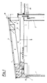
- FIG. 1 a partial section through a landfill container - in the left-hand area during filling and in the right-hand area after dismantling the roof and applying the surface seal -
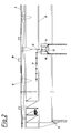
- Fig. 2 is a partial longitudinal section through the main girder of the roof with feeder belt
- Fig. 3 is a cut-out partial view of the container
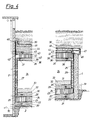
- Fig. 4 is a partial section through the container in the filled and covered state.
- the deep container shown is a cylinder container with a reinforced concrete jacket 1 and a central inspection shaft 2, which rest freely on a base 3 (grown ground or strip foundation), so that the jacket can yield to the outside as a result of the filling.
- the floor of the inspection shaft 2 and the floor area between the inspection shaft 2 and casing 1 is covered with leveling concrete.
- the container roof with integrated feeder and circular conveyor consists of a covering 4, which is supported by purlins 5 of binders 6, which are supported at one end - at 8 - on the casing 1 and at the other end - at 8 - on a central box section 9, which in turn - at 10 - is supported on the jacket 1.
- a feeder belt 11 runs in the box profile, which conveys landfill material from outside to the central discharge hopper 12, and a folding ladder is provided on the underside of the profile.
- the landfill material arrives at the discharge belt 13 of a circular conveyor 14, which in turn is a box section that rotates on a peripheral roller guide 15 on the casing 1 and a central roller guide 16 on the inspection shaft 2.
- a trolley crane 17 is guided on the upper chord of the box section; the discharge belt 13 is a tier belt, so that the dumping of the landfill material into the container can take place at any point along the circular conveyor 14.
- the roof covering 4 has ventilation hoods 18 and roof windows 19 which serve as explosion flaps.
- a first surface filter layer 20 is applied to the leveling concrete between the access shaft 2 and the casing 1, the surface of which is sloping towards the access shaft, for example, has a 4% inclination, into which a drainage pipe array 21 is inserted in a star shape descending into the inspection shaft 2.
- the surface filter layer is advantageously roof-like, so that it is highest in the middle between two neighboring drainage pipes and has the lowest height in the area of the drainage pipes, so that flat drainage surfaces are formed, as is the case, for example, in EP-A 0 130 773 Fig. 4 and 5, for peripheral drainage with an external ring line is known.
- the surface of the first surface filter layer is covered with a liquid and gas-permeable plastic net or fleece 22 onto which a first mineral sealing layer 23, in particular made of clay minerals, is applied, the flat surface of which in turn is inclined towards the inspection shaft 2.
- the surface of the first mineral sealing layer 23 is covered with a liquid and gas-tight HDPE film, for example a thickness of about 3 or higher, as a floor / side sealing apron 24 which is pulled up snugly against the outer wall of the inspection shaft 2 and the inner wall of the jacket and in the transition areas floor / side wall each has an expansion compensation fold 25.
- a radial annular sealing layer 26 which fits snugly against the bottom / side sealing apron 24 is arranged, which is likewise preferably formed from clay minerals and is secured against the interior of the container by a metal support profile, whereby a corrugated copper sheet 27 is provided centrally and a corrugated steel sheet 28 is provided radially.
- the remaining part of the surface of the first mineral sealing layer 23 is in turn covered with a plastic net or fleece 29 and a second mineral surface filter layer 30 with a second drainage pipe array 31 is arranged above it.
- the second surface filter layer 30 and the second drainage tube set 31 are designed and arranged in the same way as the first surface filter layer 20 and the first tube set 21, it being possible for the second drainage tubes 31 to be arranged offset in the vertical direction with respect to the first drainage tubes 21.
- the support profiles 27 and 28 rest on the second surface filter layer 30, which in turn is covered with a plastic net or nonwoven 32, to which a porous protective layer 33, in particular a bed of classified waste, is applied.
- the landfill material 34 is then stored on this protective layer 33.
- the second surface filter layer 30 with the drainage pipe coulter 31 serves to collect and discharge liquid escaping from the stored landfill body.
- pipelines for supplying process gas to the landfill material can furthermore be provided, which advantageously also run in a radial manner, but can also be ring lines. If necessary, the drainage pipes can also be used to introduce process gas into the landfill.
- the first surface filter layer 20 with drainage pipe coulter 21 serves for the detection and removal of leakage liquid which penetrates downward into the first surface filter layer 20 if the bottom / side sealing apron 24 fails and the first mineral sealing layer 23 fails.
- the individual drainage pipes 21 are individually monitored by measuring devices (also optically or visually), so that a quick localization of leaks is possible.
- a pressure / suction system is advantageously provided in the first and / or in the second surface filter layer, with which it is specifically possible to put individual or all drainage pipes 21 or 31 under negative or positive pressure or to locally leak through counterpressure avoid. In this way it is e.g. possible to relieve the pressure on the base seal, especially its sealing film.
- injection tubes known per se are advantageously provided in the first surface filter layer 20, with which a sealant can be introduced in the area of leak points.
- the landfill 34 under or over which a thin cover layer of surface filter material may be introduced into the container, is uniformly distributed in the usual manner and, if necessary, compacted and, after filling to the highest mark, covered with a plastic net or fleece 35, over which a third surface filter layer 36 is applied, on the one hand a gas drainage pipe 37 and on the other hand a liquid introduction system 38 (the reference numerals 37 and 38 are arbitrarily set and do not say about the arrangement of the individual pipes), so that it is not only possible to discharge gases formed in the landfill , eg suction, but through the interaction of the pipe systems in the second 30 and third 36 areas filter layer to flush the landfill material with liquids and / or gases. All pipe and pipe systems run over the access shaft 2; the gas and / or liquid treatment devices, not shown, for cleaning, extracting valuable materials and / or metering chemicals are separated from the landfill container and preferably arranged during the day.
- the third surface filter layer 36 is in turn covered with a plastic net or fleece 39 and a second mineral sealing layer 40 is applied over it, which connects the inner and outer ring sealing layer 26 to form a unit.
- the second mineral sealing layer 40 is poured over the upper edge of the casing 1 and is formed with a sloping surface (inclination e.g. 1%) towards the access shaft 2.
- the peripheral edge of the ceiling / side sealing apron is also raised, as will be described in more detail.
- a plastic net or fleece 43 is in turn spread over the ceiling / side sealing apron 41 and a fourth surface filter layer 44 with drainage pipes 45 is formed thereon, which is drained into the access shaft 2 and the surface of which is sloping towards the jacket 1 (inclination, for example, 2%).
- the outer edge of the ceiling / side sealing apron 41 is pulled up over the outer edge of the fourth surface filter layer 44.
- a cover plate 46 projecting outwardly beyond the jacket 1 and outwardly inclined is arranged, which can be cast on site with walk-on covers, preferably as adjacent individual segments, or is formed from overlapping finished segments that can be lifted off.
- the cover plate 46 has an outer flange with two downwardly directed ribs, of which the outer rib 47 engages over the jacket 1 and the inner rib 48 is designed so that it rests on the second mineral sealing layer 40 and with its outer surface sealing against the the upper edge of the jacket 1 raised bottom / side apron 24 can slide down during the raised outer edge of the ceiling / side sealing apron 41 is held sealingly between the inner surface of the inner rib 48 and the fourth surface filter layer 44.
- the cover plate 46 together with the third 36 and fourth 40 surface filter layers and the second mineral sealing layer 40 arranged therebetween can go with the sinking of the landfill material during its storage and treatment in the container.
- a corresponding guide for the cover plate which spans an upwardly directed flange 49 of the cover plate 46, can be seen.
- the cover plate 46 is covered with a fifth surface filter layer 50, which, like the cover plate, has a slope to the outside and above which there is a usual surface filling, it being, of course, favorable to ensure growth that binds to the surface water.
- a supply air duct 51 and the electrical supply are guided from the outside below the tank bottom into the access shaft 2; it is possible, if necessary, to route all supply and disposal lines through the access shaft 2, which, as can be seen from FIG. 1, is covered accordingly after the roof structure has been dismantled.
- the surface of the cover plate 46 is in the usual manner, e.g. using bitumen paint, isolated.
- the first and second surface filter layers 20 and 30 each have a thickness of 50 cm, the plastic nets or fleeces 23, 38 and 32 each have a surface weight of 750 g / m2, the first mineral sealing layer has a thickness of 3 x 20 cm, the protective layer 30 a thickness of 50 cm, the radial ring sealing layer a thickness of 20 cm, the plastic nets or fleeces 35, 39 and 43 each have a basis weight of 200 g / m2, the third surface filter layer 36 a thickness of 30 cm, the second mineral sealing layer 40 a thickness of 40 to 45 cm, the fourth surface filter layer a thickness of 100 cm on the outer wall of the inspection shaft 2 and 20 cm on the outer edge, the cover plate 46 a thickness of 25 cm and the fourth surface filter layer 50 a thickness of 40 cm on.
- the backfilling should have about 100 to 160 cm of sub-floor, about 15 cm of humus above.
- the surface filter layers are, for example, gravel with grain sizes from 16 to 32 mm.
- the various drainage and piping systems are designed to be corrosion-resistant in the usual way, e.g. Stoneware or metal pipes.
- the diameter of the drainage pipes 21, 31 and 45 is e.g. 200 mm.
- any supporting profiles 27, 28 on metal can also be used with the requirement of corrosion resistance and the requirement that they are at different points in the voltage series, that is to say are able to form a primary element with one another. If external excitation is used, the support profiles can also consist of the same material. If necessary, it is also considered to introduce externally excited electrode lances into the landfill to enable locally targeted processes.
- containers can also be provided, some of which protrude from the floor or are pure elevated containers.
- a floor pan can be provided for the container, in particular made of corrosion-protected steel or aluminum.
- liquids and / or gases also include vapors, for example water vapor.
Landscapes
- Engineering & Computer Science (AREA)
- Environmental & Geological Engineering (AREA)
- Life Sciences & Earth Sciences (AREA)
- Hydrology & Water Resources (AREA)
- General Life Sciences & Earth Sciences (AREA)
- Mining & Mineral Resources (AREA)
- Paleontology (AREA)
- Civil Engineering (AREA)
- General Engineering & Computer Science (AREA)
- Structural Engineering (AREA)
- Processing Of Solid Wastes (AREA)
- Refuse Collection And Transfer (AREA)
- Water Treatment By Sorption (AREA)
Applications Claiming Priority (2)
| Application Number | Priority Date | Filing Date | Title |
|---|---|---|---|
| AT0203287A AT388122B (de) | 1987-08-12 | 1987-08-12 | Verfahren zum behandeln von deponiegut, deponiebehaelter, insbesondere zur durchfuehrung dieses verfahrens, sowie abnehmbares dach fuer deponiebehaelter |
| AT2032/87 | 1987-08-12 |
Publications (2)
| Publication Number | Publication Date |
|---|---|
| EP0303591A2 true EP0303591A2 (fr) | 1989-02-15 |
| EP0303591A3 EP0303591A3 (fr) | 1990-03-28 |
Family
ID=3526338
Family Applications (1)
| Application Number | Title | Priority Date | Filing Date |
|---|---|---|---|
| EP88890204A Withdrawn EP0303591A3 (fr) | 1987-08-12 | 1988-08-04 | Procédé de traitement de matières dans une décharge, réservoir de mise à la décharge pour mettre en oeuvre ledit procédé et toit amovible pour ledit réservoir |
Country Status (3)
| Country | Link |
|---|---|
| US (1) | US4936706A (fr) |
| EP (1) | EP0303591A3 (fr) |
| AT (1) | AT388122B (fr) |
Cited By (1)
| Publication number | Priority date | Publication date | Assignee | Title |
|---|---|---|---|---|
| AT397052B (de) * | 1990-10-22 | 1994-01-25 | Kastner Helmut F Ing | Verfahren und anordnung zur lagerung von müll in einer deponie, vorzugsweise reaktordeponie |
Families Citing this family (10)
| Publication number | Priority date | Publication date | Assignee | Title |
|---|---|---|---|---|
| FR2686275B1 (fr) * | 1992-01-17 | 1994-04-01 | Sarp Industries | Procede et installation pour le stockage de dechets solidifies. |
| US5269634A (en) * | 1992-08-31 | 1993-12-14 | University Of Florida | Apparatus and method for sequential batch anaerobic composting of high-solids organic feedstocks |
| US5286141A (en) * | 1993-02-12 | 1994-02-15 | Vigneri Ronald J | Method and system for remediation of groundwater contamination |
| CN1112778A (zh) * | 1993-07-19 | 1995-11-29 | 尤尼特尼克公共设施公司 | 清除垃圾的方法和设备 |
| US5636940A (en) * | 1995-11-29 | 1997-06-10 | Landfill Technologies, Inc. | Apparatus and method for gas and/or liquid exchange between an area outside and an area inside a bulk material pile |
| US5988947A (en) * | 1997-11-04 | 1999-11-23 | Bruso; Bruce L. | Multi-section soil remediation device |
| US6206098B1 (en) | 1997-11-14 | 2001-03-27 | Kent Cooper | In situ water and soil remediation method and system |
| US5967230A (en) * | 1997-11-14 | 1999-10-19 | Cooper; Kent | In situ water and soil remediation method and system |
| US6502633B2 (en) | 1997-11-14 | 2003-01-07 | Kent Cooper | In situ water and soil remediation method and system |
| US6143394A (en) * | 1998-08-18 | 2000-11-07 | Kg Fibers, Inc. | Nonwoven sorbent manhole apron |
Family Cites Families (15)
| Publication number | Priority date | Publication date | Assignee | Title |
|---|---|---|---|---|
| US3586624A (en) * | 1970-03-02 | 1971-06-22 | Werner Co | Waste disposal method and system |
| US3732697A (en) * | 1972-01-14 | 1973-05-15 | R Dickson | Waste disposal method and facility |
| US4166709A (en) * | 1978-08-03 | 1979-09-04 | Stabatrol Corporation | Method for vaulting hazardous chemical waste materials |
| US4252462A (en) * | 1979-01-30 | 1981-02-24 | Industrial Service International Corp. | Chemical landfill |
| US4352601A (en) * | 1980-08-18 | 1982-10-05 | Stabatrol Corporation | Permanent bin for temporary storage of hazardous materials |
| US4362434A (en) * | 1980-10-28 | 1982-12-07 | Stabatrol Corporation | Permanent disposal vault for hazardous chemical waste materials |
| US4335978A (en) * | 1981-04-07 | 1982-06-22 | Mutch Robert D | Induced intragradient system for secure landfill |
| US4430021A (en) * | 1981-11-23 | 1984-02-07 | Ecological Professional Industries, Inc. | Secure chemical waste landfill |
| AU547913B2 (en) * | 1982-08-30 | 1985-11-14 | Chemfix Technologies Inc. | Treating organic waste |
| DE3303067C2 (de) * | 1983-01-29 | 1986-02-20 | Strabag Bau-AG, 5000 Köln | Lagerstätte für Abfälle und Verfahren zu ihrem Füllen und Verschließen |
| US4464081A (en) * | 1983-06-29 | 1984-08-07 | Rollins Environmental Services, Inc. | Process and structure for storing and isolating hazardous waste |
| US4591443A (en) * | 1984-11-08 | 1986-05-27 | Fmc Corporation | Method for decontaminating a permeable subterranean formation |
| EP0185831B2 (fr) * | 1984-12-22 | 1995-02-15 | Harbauer GmbH & Co. KG | Dispositif pour le nettoyage continu du sol pour l'élimination d'éléments polluants |
| DE3521947A1 (de) * | 1985-06-14 | 1987-01-15 | Holzmann Philipp Ag | Behaelter fuer deponiefaehige abfaelle |
| DE3525701A1 (de) * | 1985-07-18 | 1987-01-22 | Didier Werke Ag | Verfahren zur sanierung von deponien |
-
1987
- 1987-08-12 AT AT0203287A patent/AT388122B/de not_active IP Right Cessation
-
1988
- 1988-08-04 EP EP88890204A patent/EP0303591A3/fr not_active Withdrawn
- 1988-08-10 US US07/230,551 patent/US4936706A/en not_active Expired - Fee Related
Cited By (1)
| Publication number | Priority date | Publication date | Assignee | Title |
|---|---|---|---|---|
| AT397052B (de) * | 1990-10-22 | 1994-01-25 | Kastner Helmut F Ing | Verfahren und anordnung zur lagerung von müll in einer deponie, vorzugsweise reaktordeponie |
Also Published As
| Publication number | Publication date |
|---|---|
| ATA203287A (de) | 1988-10-15 |
| US4936706A (en) | 1990-06-26 |
| AT388122B (de) | 1989-05-10 |
| EP0303591A3 (fr) | 1990-03-28 |
Similar Documents
| Publication | Publication Date | Title |
|---|---|---|
| US3705851A (en) | Waste disposal system | |
| US5201609A (en) | Cellular landfill process and apparatus | |
| EP0292941A2 (fr) | Agencement pour retenir les éléments nocifs des eaux d'infiltration polluées d'une décharge de déchets par une couche d'étanchéité minérale et procédé de fabrication de ladite couche | |
| EP0187874A1 (fr) | Emplacement pour le dépôt de déchets et procédé pour sa fabrication | |
| EP0303591A2 (fr) | Procédé de traitement de matières dans une décharge, réservoir de mise à la décharge pour mettre en oeuvre ledit procédé et toit amovible pour ledit réservoir | |
| DE3423438C2 (de) | Vorrichtung zur Fassung von Sickerwasser aus Deponien | |
| EP0374555B1 (fr) | Méthode pour l'étanchement de surface des dépôts de déchets | |
| DE4317976A1 (de) | Abfallablagerungsgelände | |
| DE3445127A1 (de) | Sohlenkonstruktion fuer eine abfalldeponie | |
| DE4425061C1 (de) | Permeables Behandlungsbett zur Reinigung kontaminierter Grundwasserströme in situ | |
| DE3631807A1 (de) | Behaeltersystem zur lagerung von abfaellen | |
| DE2430371A1 (de) | Verfahren zur deponierung von umweltgefaehrdenden abfaellen | |
| EP0204895B1 (fr) | Réservoir pour déchets aptes à être mis à la décharge | |
| DE3415729A1 (de) | Niederschlagsableitende sperrdecke fuer muelldeponien | |
| EP0884117B1 (fr) | Dispositif pour évacuer les gaz d'une décharge | |
| DE3607499C2 (fr) | ||
| DE3415883A1 (de) | Verfahren zur abdichtung kontaminierter muellkoerper gegenueber ihrer lagerstaette | |
| DE3609973A1 (de) | Sickerwassersammelschacht fuer deponien | |
| DE3300464A1 (de) | Verfahren zum entgasen einer deponie von industrierueckstaenden, insbes. von muell und abfaellen | |
| DE3425788A1 (de) | Muelldeponie zur gewinnung von zersetzungsgasen | |
| DE4400183A1 (de) | Drän-Entwässerungselement für Abfalldeponien und sonstige Verwendung im Erd-, Grund- und Wasserbau | |
| WO1989007493A1 (fr) | Depot temporaire ou definitif de dechets dangereux et procede d'installation de depots de dechets | |
| DE4211667A1 (de) | Verfahren zur Behandlung von Abfall, insbesondere Hausmüll, in einem zumindest teilweise umschlossenen Abfallkörper, z. B. einer Deponie | |
| DE3703442A1 (de) | Verfahren und vorrichtung zum sanieren von vorhandenen deponien, sowie kontaminierten industriestandorten | |
| DE29805120U1 (de) | Anordnung zur Konstruktion und Gestaltung von Deponien |
Legal Events
| Date | Code | Title | Description |
|---|---|---|---|
| PUAI | Public reference made under article 153(3) epc to a published international application that has entered the european phase |
Free format text: ORIGINAL CODE: 0009012 |
|
| AK | Designated contracting states |
Kind code of ref document: A2 Designated state(s): AT BE CH DE ES FR GB GR IT LI LU NL SE |
|
| PUAL | Search report despatched |
Free format text: ORIGINAL CODE: 0009013 |
|
| AK | Designated contracting states |
Kind code of ref document: A3 Designated state(s): AT BE CH DE ES FR GB GR IT LI LU NL SE |
|
| 17P | Request for examination filed |
Effective date: 19900720 |
|
| 17Q | First examination report despatched |
Effective date: 19910613 |
|
| STAA | Information on the status of an ep patent application or granted ep patent |
Free format text: STATUS: THE APPLICATION IS DEEMED TO BE WITHDRAWN |
|
| 18D | Application deemed to be withdrawn |
Effective date: 19911224 |