EP0303685B1 - Verfahren zum parallelen schusseintrag mit gleichmässiger dichte bei mehreren dichtgelagerten enden sowie hergestelltes produkt - Google Patents
Verfahren zum parallelen schusseintrag mit gleichmässiger dichte bei mehreren dichtgelagerten enden sowie hergestelltes produkt Download PDFInfo
- Publication number
- EP0303685B1 EP0303685B1 EP19880902742 EP88902742A EP0303685B1 EP 0303685 B1 EP0303685 B1 EP 0303685B1 EP 19880902742 EP19880902742 EP 19880902742 EP 88902742 A EP88902742 A EP 88902742A EP 0303685 B1 EP0303685 B1 EP 0303685B1
- Authority
- EP
- European Patent Office
- Prior art keywords
- yarns
- yarn
- shuttle
- elements
- structural
- Prior art date
- Legal status (The legal status is an assumption and is not a legal conclusion. Google has not performed a legal analysis and makes no representation as to the accuracy of the status listed.)
- Expired - Lifetime
Links
- 238000000034 method Methods 0.000 title claims abstract description 42
- 238000003780 insertion Methods 0.000 title abstract description 13
- 230000037431 insertion Effects 0.000 title description 2
- 239000004744 fabric Substances 0.000 claims abstract description 71
- 238000012546 transfer Methods 0.000 claims abstract description 56
- 230000008569 process Effects 0.000 claims abstract description 32
- 230000014759 maintenance of location Effects 0.000 claims description 11
- 230000009471 action Effects 0.000 claims description 5
- 239000011347 resin Substances 0.000 claims description 5
- 229920005989 resin Polymers 0.000 claims description 5
- 230000000717 retained effect Effects 0.000 claims description 5
- 230000000881 depressing effect Effects 0.000 claims description 2
- 229920006395 saturated elastomer Polymers 0.000 claims 1
- 238000004519 manufacturing process Methods 0.000 description 7
- 239000000835 fiber Substances 0.000 description 5
- 230000007246 mechanism Effects 0.000 description 5
- 238000005516 engineering process Methods 0.000 description 4
- 238000012986 modification Methods 0.000 description 4
- 230000004048 modification Effects 0.000 description 4
- OKTJSMMVPCPJKN-UHFFFAOYSA-N Carbon Chemical compound [C] OKTJSMMVPCPJKN-UHFFFAOYSA-N 0.000 description 3
- 235000014676 Phragmites communis Nutrition 0.000 description 2
- 230000008021 deposition Effects 0.000 description 2
- 238000006073 displacement reaction Methods 0.000 description 2
- 229910002804 graphite Inorganic materials 0.000 description 2
- 239000010439 graphite Substances 0.000 description 2
- 238000005470 impregnation Methods 0.000 description 2
- 229920000049 Carbon (fiber) Polymers 0.000 description 1
- 238000013459 approach Methods 0.000 description 1
- 230000008901 benefit Effects 0.000 description 1
- 238000004364 calculation method Methods 0.000 description 1
- 229910052799 carbon Inorganic materials 0.000 description 1
- 239000004917 carbon fiber Substances 0.000 description 1
- 239000000969 carrier Substances 0.000 description 1
- 239000007795 chemical reaction product Substances 0.000 description 1
- 239000002131 composite material Substances 0.000 description 1
- 238000010276 construction Methods 0.000 description 1
- 230000007423 decrease Effects 0.000 description 1
- 230000003247 decreasing effect Effects 0.000 description 1
- 230000000994 depressogenic effect Effects 0.000 description 1
- 238000010586 diagram Methods 0.000 description 1
- 230000001747 exhibiting effect Effects 0.000 description 1
- 239000011152 fibreglass Substances 0.000 description 1
- 238000009787 hand lay-up Methods 0.000 description 1
- 238000010348 incorporation Methods 0.000 description 1
- 238000009940 knitting Methods 0.000 description 1
- 239000000463 material Substances 0.000 description 1
- 238000011017 operating method Methods 0.000 description 1
- 238000012856 packing Methods 0.000 description 1
- 229920002647 polyamide Polymers 0.000 description 1
- 229920000728 polyester Polymers 0.000 description 1
- 238000003825 pressing Methods 0.000 description 1
- 238000012545 processing Methods 0.000 description 1
- 239000000047 product Substances 0.000 description 1
- 238000007790 scraping Methods 0.000 description 1
- 230000001360 synchronised effect Effects 0.000 description 1
- 229920002994 synthetic fiber Polymers 0.000 description 1
- 229920001187 thermosetting polymer Polymers 0.000 description 1
- 239000004634 thermosetting polymer Substances 0.000 description 1
- 239000002699 waste material Substances 0.000 description 1
Images



Classifications
-
- D—TEXTILES; PAPER
- D04—BRAIDING; LACE-MAKING; KNITTING; TRIMMINGS; NON-WOVEN FABRICS
- D04H—MAKING TEXTILE FABRICS, e.g. FROM FIBRES OR FILAMENTARY MATERIAL; FABRICS MADE BY SUCH PROCESSES OR APPARATUS, e.g. FELTS, NON-WOVEN FABRICS; COTTON-WOOL; WADDING ; NON-WOVEN FABRICS FROM STAPLE FIBRES, FILAMENTS OR YARNS, BONDED WITH AT LEAST ONE WEB-LIKE MATERIAL DURING THEIR CONSOLIDATION
- D04H3/00—Non-woven fabrics formed wholly or mainly of yarns or like filamentary material of substantial length
- D04H3/02—Non-woven fabrics formed wholly or mainly of yarns or like filamentary material of substantial length characterised by the method of forming fleeces or layers, e.g. reorientation of yarns or filaments
- D04H3/04—Non-woven fabrics formed wholly or mainly of yarns or like filamentary material of substantial length characterised by the method of forming fleeces or layers, e.g. reorientation of yarns or filaments in rectilinear paths, e.g. crossing at right angles
-
- Y—GENERAL TAGGING OF NEW TECHNOLOGICAL DEVELOPMENTS; GENERAL TAGGING OF CROSS-SECTIONAL TECHNOLOGIES SPANNING OVER SEVERAL SECTIONS OF THE IPC; TECHNICAL SUBJECTS COVERED BY FORMER USPC CROSS-REFERENCE ART COLLECTIONS [XRACs] AND DIGESTS
- Y10—TECHNICAL SUBJECTS COVERED BY FORMER USPC
- Y10T—TECHNICAL SUBJECTS COVERED BY FORMER US CLASSIFICATION
- Y10T428/00—Stock material or miscellaneous articles
- Y10T428/24—Structurally defined web or sheet [e.g., overall dimension, etc.]
- Y10T428/24033—Structurally defined web or sheet [e.g., overall dimension, etc.] including stitching and discrete fastener[s], coating or bond
-
- Y—GENERAL TAGGING OF NEW TECHNOLOGICAL DEVELOPMENTS; GENERAL TAGGING OF CROSS-SECTIONAL TECHNOLOGIES SPANNING OVER SEVERAL SECTIONS OF THE IPC; TECHNICAL SUBJECTS COVERED BY FORMER USPC CROSS-REFERENCE ART COLLECTIONS [XRACs] AND DIGESTS
- Y10—TECHNICAL SUBJECTS COVERED BY FORMER USPC
- Y10T—TECHNICAL SUBJECTS COVERED BY FORMER US CLASSIFICATION
- Y10T428/00—Stock material or miscellaneous articles
- Y10T428/24—Structurally defined web or sheet [e.g., overall dimension, etc.]
- Y10T428/24132—Structurally defined web or sheet [e.g., overall dimension, etc.] including grain, strips, or filamentary elements in different layers or components parallel
-
- Y—GENERAL TAGGING OF NEW TECHNOLOGICAL DEVELOPMENTS; GENERAL TAGGING OF CROSS-SECTIONAL TECHNOLOGIES SPANNING OVER SEVERAL SECTIONS OF THE IPC; TECHNICAL SUBJECTS COVERED BY FORMER USPC CROSS-REFERENCE ART COLLECTIONS [XRACs] AND DIGESTS
- Y10—TECHNICAL SUBJECTS COVERED BY FORMER USPC
- Y10T—TECHNICAL SUBJECTS COVERED BY FORMER US CLASSIFICATION
- Y10T428/00—Stock material or miscellaneous articles
- Y10T428/249921—Web or sheet containing structurally defined element or component
- Y10T428/249924—Noninterengaged fiber-containing paper-free web or sheet which is not of specified porosity
Definitions
- This invention pertains to the art of manufacturing plys of structural fabric characterized by the presence of parallel, obliquely biased yarns of high modulus stitched together into a uniform ply, the ply having a high uniform density. More specifically, the invention provides a method for making plys of structural fabric of high yarn density, the yarns being parallel, biased and stitched together in a ply of uniform density through a weft-insertion process.
- One of the most productive and cost-efficient methods of providing plys of structural yarns is the weft-insertion process, where a plurality of yarns is directed back and forth across a space defined by two advancing rows of hooks or retaining elements, the yarns being retained at each crossing by those retaining elements. As the yarns are retained by these elements, the hooks are advanced into a stitching machine, where stitching yarns are applied across the structural yarns.
- a single ply of fabric, with yarns oriented in a direction of 90° to the direction of the fabric, the yarns being relatively widely spaced is produced. The yarns are widely spaced due to the need to pass the yarns and carrier elements between the hooks, or otherwise retain them.
- Density of the fabric is commonly increased by making the infeed of laid-in yarns to the stitching machine higher than the output of stitched fabric. The yarns thus tend to "pile-up" in the machine, increasing density. Methods employing a differential between infeed and output are not applicable to biased or multi-ply fabrics or any other situation where infeed and output must be equal.
- U.S. Patent 4,325,999 in Figure 11, columns 13 and 14, illustrates a method by which a 2-layer non-structural fabric can be produced, wherein each of the yarns in each layer is parallel, the yarns in respective layers being aligned at 90° to each other and 45° with respect to the long axis of the fabric.
- the apparatus requires the yarns to actually pass through spaces between the pins or retaining elements on the conveyor, and then turn around and pass back across those elements.
- the resulting fabric is therefore necessarily of low density, and not suitable for the above-described applications.
- these rake embodiments cannot be used to achieve high density because the spacing of transfer elements on the rake is required to be the same as the yarn density on the shuttle. At high densities, necessarily some yarns will be impaled by the transfer elements, rather than properly engaged. Upon movement of the rake, breakage of the yarns and resulting faults are likely to occur.
- an available, reliable method for providing high, uniform density structural fabric plies wherein the fibers are arranged in parallel is a single-end weft-insertion, where only a single yarn end is passed between the conveyors by the shuttle, or a machine where infeed and output density are not equal.
- the former process is capable of extreme reliability, but it is extraordinarily slow.
- the latter is limited to non-biased fabrics, those laid in at an angle of 90° with respect to the fabric. As a result, neither is a commercially acceptable method for producing the desired fabrics.
- a further problem presented by commercial demands is the need to provide a wide variety of fabrics having different, but uniform, densities through a single fabrication technology. Even within a single application, e.g. aerospace, there is a need to be able to provide fabrics of a wide range of densities but common appearance and manufacturing.
- a further process for forming a ply of structural fabric comprised of parallel structural yarns is disclosed in DE-A-3343048.
- bends of yarns are laid between two conveyors wherein the bends are parallel to each other and laid in a distance that the yarns from bends to bends are in an equal distance to each other. This is achieved by a racking motion of the yarns outside the conveyors over a distance which is equal to the width of each bend.
- the density of the yarns within such a ply is defined by the construction of the shuttle which guides the yarns through holes which are positionned on the shuttle side by side.
- One object of this invention is to provide a process whereby structural fabric plys of high modulus yarns in parallel array, and high and uniform density, without deviation from that parallelity, can be provided.
- a process which involves a conventional weft-insertion shuttle and conveyor arrangement, such that a shuttle, provided with a reed, traverses rapidly back and forth over a space defined by two in-feed conveyors which advance toward a stitching machine.
- the shuttle carries a plurality of yarns.
- the shuttle passes over the conveyor, and the yarns carried by the shuttle are transferred to yarn transfer elements, which are positioned outside the conveyor, and lie parallel to the conveyor.
- These yarn transfer elements then immediately move or "rack", parallel to the conveyors, in the direction opposite to the advance of the conveyors. This racking is achieved before the shuttle has passed back over the conveyor adjacent the engaged yarn transfer elements on its return trip.
- the yarn transfer elements move sychronously with the conveyor to their original position.
- the yarn transfer elements release the yarns, which are then engaged by the needles, hooks, or similar yarn holding or retention devices provided on the conveyors.
- the yarn transfer elements which may be units of a plurality of needles or racks similar to, or identical, with those provided on the conveyor, are spaced no closer together than 0,762 mm (0.3 inches) or whatever minimum tolerance is necessary to ensure positive placement and engagement of the yarn with smooth operation.
- the shuttle then travels over to the other conveyor, where another yarn transfer element is positioned, and the same operation takes place.
- each band of yarns laid down by the shuttle is overlaid, to some degree, with the preceding band or bands, by virtue of the racking motion of the yarn transfer elements.
- This racking motion together with the speed of advance of the conveyors, can be predetermined, given the number of yarns to be carried on the shuttle, and the yarn spacing on the shuttle, to give any desired yarn density.
- the racking motion herein is designed to ensure uniform density over a wide range of densities.
- Yarn holding elements such as pins or hooks, may be spaced on the conveyors as desired.
- Current operating methods make use of conveyors with 12 or 14 elements per 25,4 mm (inch).
- more than one yarn lies between given pairs of adjacent holding elements and/or yarns are impaled on the elements. While, on a microscopic scale, this causes some "bundling", the packing pattern of the yarns eliminates any perceptible deviations.
- This can be further controlled by increasing the number of elements per 25,4 mm (inch).
- the maximum number of elements per 25,4 mm (inch) is limited by the space necessary to firmly seat the yarn between two needles, or impale the yarns.
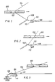
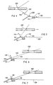
- Figures 1-3 and 4-7 illustrate alternative methods of engagement and release of the yarn by the yarn transfer elements.
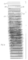
- Figure 8 illustrates one type of fabric that may be produced by this invention, and the overlay pattern employed.
- Figure 9 illustrates an alternative fabric and overlay pattern.
- Figures 11-15 illustrate the process, inhancing clarity by limiting number of yarns laid down by the shuttle at each pass.
- this invention can be practiced using machinery that is entirely conventional, or that can be adapted without major modification.
- the basic elements of a weft insertion apparatus are all applicable to the invention.
- two "endless" conveyors provided with hooks or other yarn retention elements are mounted and provided with a synchronous drive, which advances the hooks into a stitching machine, where the yarns are stitched together, and removed from the hooks.
- the looped portion of the yarns, that which is looped around the retention elements, is frequently trimmed away at this stage.
- This apparatus is also provided with at least one weft-insertion shuttle or carriage, which traverses across the conveyors, and is provided with the ability to depress the yarns carried by the shuttle at either end of its traverse, so as to bring them within reach of engagement with the yarn transfer elements to be used.
- a particularly preferred mechanism is disclosed in U.S. Patent 4,444,025, the disclosure of which is incorporated herein by reference. That particular carrier mechanism is characterized by the provision of a slanted cam, which allows the rotation of the bars of the shuttle depressing the yarns for engagement to be relatively gentle, and at the same time reducing weight, and improving performance, of the shuttle.
- the yarn transfer elements comprise a support upon which are mounted a plurality of hooks, pins or other devices to temporarily engage the yarn. These devices are provided with a slanted edge on the end a "hook" at the free of the engagement device.
- the "racking" motion of the transfer element is effected.
- the yarn slides off the needle hook and onto the yarn holding elements of the conveyor due to the decreasing angle between the shuttle and the engagement device. The transfer element then returns to its original position.
- the hooks, etc. to be employed are conventionally employed on the conveyors of currently available weft-insertion apparatus, and are commercially available.
- the parallel yarns are stitched together through conventional technology, and exit the stitching machine as a uniform structural ply, suitable for incorporation in structural articles for resin impregnation.
- yarn transfer needle 108 has engaged the yarn by "racking" in a direction parallel to yarn retention elements 110 and in a direction opposite to their advance.
- the shuttle has not passed back over yarn holding elements 110 before this racking is completed.
- each yarn retention element may be comprised of a plurality of pins, as illustrated, in order to ensure uniform holding of the yarn by the retention elements.
- FIGs 4-7 An alternative embodiment of operation is illustrated in Figures 4-7.
- the shuttle is illustrated in the same position as in Figure 1, discussed above.
- an additional strip-off bar 114 is featured, carried on the carriage (not illustrated) supporting yarn transfer element 108.
- the racking action of the yarn transfer element can be employed to insure that each band laid down by the shuttle overlaps with bands previously laid down, such that an extremely high and uniform density of yarns in the fabric can be obtained.
- the results of such a lay down is illustrated in Figure 8.
- the fabric has a low density, and does not meet the specification set for such a fabric, which in this example is a density of 16 lines or yarns per 25,4 mm (inch). However, in the center of the fabric, this density is easily achieved. It should be noted that the fact that the beginning and ends of each run do not meet the required density specifications does not necessarily introduce additional waste or extra cost, as these portions of any run in conventional processes are usually trimmed and discarded.
- the controlling parameters were the desired density, 16 ends per 25,4 mm (inch) the number of yarns the shuttle can carry, and critically, yarn spacing on the shuttle and hook spacing on the transfer element, which was 12,7 mm (0.5 inches).
- the racking distance, or band displacement is 27 mm (1.0625 inches).
- the fabric has been illustrated without the secondary stitching yarns, for ease of illustration. Once passing through the stitching machine, however, this fabric would be held together by secondary yarns stitched through the fabric.
- Figure 9 is a similar diagram, where the parameters controlling the amount of racking have been changed.
- the desired density is still 16 yarns per 25,4 mm (inch)
- the shuttle carries 21 yarns ends. These are first laid down as yarn ends 206, which are followed by the deposition of bands 208, on the return trip of the shuttle.
- Figure 11 shows the first band of yarns 11 laid by the shuttle on its way from conveyor 1 to conveyor 2.
- Figure 14 shows the corresponding further step with yarns 14 following the rules according to Figures 11-13.
- the relationship between the strands on the shuttle, the racking of the transfer element, the yarn spacing on the shuttle, and transfer elements and the yarn density are as follows: Yarn density in fabric as measured parallel to the conveyors: d Yarns on shuttle: b Racking of transfer element: a Yarn spacing on shuttle and transfer element hook spacing: c Width of shuttle that is strung with yarn: e Integer: n
- c can be altered according to the formula for yarn density. Unlike b and n, which are integral values, c can be any value above about 0.3.
- This system is applicable to the weft-insertion of virtually any type of yarn or fiber.
- particularly preferred yarns are those exhibiting a modulus of about 5600 kg/cm2 (8 million lbs./in.2) or more, including certain types of fiberglass, graphite and other carbon fibers, certain polyamid and other thermosetting polymers, etc.
- the yarn fiber used as the secondary yarn to stitch the parallel structural yarns into a unitary fabric ply can be selected from virtually any natural or synthetic material.
- relatively low-modulus yarns certain polyesters are extremely easy to work with, and accordingly, preferred.
- Certain embodiments, for extremely high strength applications require the use of high modulus yarns as the secondary or stitching yarns as well.
- One particularly preferred embodiment is where both the parallel yarns and the stitching yarns are comprised of graphite or other carbon-derived materials.
- the fabric may be incorporated, as is, in a multi-ply structural article, generally subsequently infused with a resin which can be cured, or first cut and shaped and then incorporated in the end product, through known technology such as hand lay-up operations, and automated equivalents.
- the individual plys produced may, depending on the stitching employed, also be suitable for the biasing process of U.S. Patent 4,567,758 and incorporated into a biased structural fabric thereby.
Landscapes
- Engineering & Computer Science (AREA)
- Textile Engineering (AREA)
- Treatment Of Fiber Materials (AREA)
- Reinforced Plastic Materials (AREA)
- Manufacturing Of Multi-Layer Textile Fabrics (AREA)
- Woven Fabrics (AREA)
- Knitting Machines (AREA)
Claims (9)
- Verfahren zum Bilden einer Lage strukturierten Gewebes, das aus parallelen strukturellen Fäden in einer gewünschten Dichte besteht, das aufweist:
Ausrichten einer Vielzahl von Fäden, die ein Band mit einer gegebenen Breite definieren, die hin und zurück über zwei parallele voneinander beabstandete fortlaufend fortschreitende Transporteure mit Hilfe eines Wagens verlaufen, der zwischen Endpositionen jenseits jedes Transporteurs hin- und herläuft,
Überführen der Fäden zu den Transporteuren am Ende jeder Hin- und Herbewegung durch Führen der Fäden an Fädenrückhalteelementen vorbei auf den Transporteur, der benachbart zum Wagen an seiner Endposition ist, und Übernehmen der Fäden auf Fadenübertragungselemente, die auf der Seite des benachbarten Transporteurs, gegenüberliegend den parallelen entgegengesetzten Trausporteur, positioniert sind, und Bewegen der Fadenübertragungselemente in einer Versatzbewegung parallel zu dem Transporteur um eine vorbestimmte Distanz in Gegenrichtung zum Vorschub des Transporteurs vor Beendigung der Bewegung des Wagens zurück über den Transporteur angrenzend zu dem Element, danach Beenden der Hin- und Herbewegung des Wagens, wodurch jedes Fadenband, das von dem Wagen gelegt wurde, etwas über das vorhergehende Band oder Bänder gelegt wird, und zwar aufgrund der Versatzbewegung der Fadenübertragungselemente, wobei die Fäden von den Fadenübertragungselementen freigegeben, durch die Fadenhalteelemente zurückgehalten und von den Transporteuren gefördert werden,
Vorwärtsbewegen der Transporteure und der darin gehaltenen Fäden in eine Nähvorrichtung, in der die Fäden zu einer strukturierten Gewebelage zusammengenäht werden, wobei die Bewegung der Fadenübertragungselemente berechnet ist, um eine gerichtete Viellagenanordnung von strukturellen Fäden in einer hohen Dichte bereit zu stellen. - Verfahren nach Anspruch 1, bei dem die Länge der Bewegung der Übertragungselemente bestimmt ist entsprechend der Beziehung

- Verfahren nach Anspruch 1, bei dem die Fäden auf dem Wagen beabstandet sind, und die Fadenübertragungselemente beabstandet sind, und zwar nicht kleiner als 0,118 cm.
- Verfahren nach Anspruch 1, worin die Dichte größer ist als ungefähr 8 Fäden pro 2,54 cm.
- Verfahren von Anspruch 1, bei dem die Fäden strukturelle Garne sind mit einem Modul von über 5.600 kg/mm².
- Verfahren von Anspruch 1, worin die Fäden von den Übertragungselementen durch die Hin- und Herbewegung des Wagens freigegeben werden, wobei der Winkel zwischen dem Wagen und dem Faden fortschreitend vermindert wird, bis der Faden von dem Fadenübertragungselement durch eine daran angebrachten schrägen Kante freigegeben wird, dabei zurückgehalten durch das Fadenhalteelement.
- Verfahren nach Anspruch 1, bei dem die Übertragung der Fäden von dem Übertragungselement zu dem Halteelement unterstützt wird durch Niederdrücken eines Abstreifstabes in Kontakt mit den Fäden, die auf dem Fadenübertragungselement zurückgehalten werden bis zu einem Punkt, der an die Fadenhalteelemente angrenzt.
- Verfahren nach Anspruch 1, worin die Lage mit den anderen Lagen der strukturellen Fäden zu einem strukturellen Viellagengewebe vernäht wird.
- Verfahren nach Anspruch 1, bei dem das strukturelle Gewebe mit einem aushärtenden Harz gesättigt wird.
Applications Claiming Priority (2)
| Application Number | Priority Date | Filing Date | Title |
|---|---|---|---|
| US07/023,690 US4774120A (en) | 1987-03-09 | 1987-03-09 | Method for multiple-end-close-set uniform density parallel weft insertion and products thereof |
| US23690 | 1987-03-09 |
Publications (3)
| Publication Number | Publication Date |
|---|---|
| EP0303685A1 EP0303685A1 (de) | 1989-02-22 |
| EP0303685A4 EP0303685A4 (de) | 1989-07-11 |
| EP0303685B1 true EP0303685B1 (de) | 1993-06-16 |
Family
ID=21816636
Family Applications (1)
| Application Number | Title | Priority Date | Filing Date |
|---|---|---|---|
| EP19880902742 Expired - Lifetime EP0303685B1 (de) | 1987-03-09 | 1988-03-09 | Verfahren zum parallelen schusseintrag mit gleichmässiger dichte bei mehreren dichtgelagerten enden sowie hergestelltes produkt |
Country Status (5)
| Country | Link |
|---|---|
| US (1) | US4774120A (de) |
| EP (1) | EP0303685B1 (de) |
| JP (1) | JP2849102B2 (de) |
| DE (1) | DE3881785T2 (de) |
| WO (1) | WO1988006969A1 (de) |
Families Citing this family (4)
| Publication number | Priority date | Publication date | Assignee | Title |
|---|---|---|---|---|
| US6620484B1 (en) * | 2000-06-06 | 2003-09-16 | The Boeing Company | Variable density stitched-composite structural elements for energy absorption |
| DE10207317C5 (de) * | 2002-02-21 | 2009-12-31 | Liba Maschinenfabrik Gmbh | Vorrichtung zum Legen von multiaxial ausgerichteten Fadenlagen |
| DE102006055497B4 (de) * | 2006-11-24 | 2009-01-02 | Karl Mayer Textilmaschinenfabrik Gmbh | Musterungshilfsvorrichtung einer Kettenwirkmaschine |
| WO2014145675A1 (en) | 2013-03-15 | 2014-09-18 | Hollander Jonathan Marc | Methods for three-dimensional weaving of composite preforms and products with varying cross-sectional topology |
Family Cites Families (3)
| Publication number | Priority date | Publication date | Assignee | Title |
|---|---|---|---|---|
| US2804973A (en) | 1951-06-09 | 1957-09-03 | Buddecke Heinrich | Yarn pack and method of and means for its preparation |
| US4325999A (en) * | 1979-11-23 | 1982-04-20 | Hitco | Bias fabric |
| US4444025A (en) * | 1982-05-11 | 1984-04-24 | Proform, Inc. | Carrier mechanism for weft insertion |
-
1987
- 1987-03-09 US US07/023,690 patent/US4774120A/en not_active Expired - Fee Related
-
1988
- 1988-03-09 DE DE88902742T patent/DE3881785T2/de not_active Expired - Fee Related
- 1988-03-09 WO PCT/US1988/000674 patent/WO1988006969A1/en not_active Ceased
- 1988-03-09 JP JP50268188A patent/JP2849102B2/ja not_active Expired - Lifetime
- 1988-03-09 EP EP19880902742 patent/EP0303685B1/de not_active Expired - Lifetime
Also Published As
| Publication number | Publication date |
|---|---|
| WO1988006969A1 (en) | 1988-09-22 |
| EP0303685A1 (de) | 1989-02-22 |
| DE3881785D1 (de) | 1993-07-22 |
| US4774120A (en) | 1988-09-27 |
| JP2849102B2 (ja) | 1999-01-20 |
| JPH01502996A (ja) | 1989-10-12 |
| EP0303685A4 (de) | 1989-07-11 |
| DE3881785T2 (de) | 1994-01-20 |
Similar Documents
| Publication | Publication Date | Title |
|---|---|---|
| EP0179859B1 (de) | Verfahren und vorrichtung zur herstellung von schrägen textilien | |
| US5074129A (en) | Formable fabric | |
| US4677831A (en) | Apparatus for laying transverse weft threads for a warp knitting machine | |
| DE69017451T2 (de) | Gerippte Strick-Webware. | |
| US6494235B1 (en) | Bias-bound fabric, method for making same and weaving machine for continuously making such a fabric | |
| CN1199786A (zh) | 在横编机上生产立体的、单面或多面纬编织物的方法 | |
| US5174134A (en) | Knitting method of thick fabric less in elasticity | |
| EP0303685B1 (de) | Verfahren zum parallelen schusseintrag mit gleichmässiger dichte bei mehreren dichtgelagerten enden sowie hergestelltes produkt | |
| US2114004A (en) | Knitted fabric and method of producing same | |
| JPS6030769B2 (ja) | 経編機 | |
| US4877470A (en) | Method for the production of bias fabrics | |
| EP0680529B1 (de) | Verfahren und einrichtung zur herstellung textiler netzartiger flächengebilde | |
| US5189769A (en) | Manufacture of a multiple biased fabric by folding | |
| US4890462A (en) | Knitted fabric | |
| US2888814A (en) | Straight knitting machine operation | |
| US4472234A (en) | Device for producing a web of parallel yarns and different complex articles comprising such a web | |
| EP0407983B1 (de) | Herstellung eines mehrfach schrägverlaufenden Stoffes durch Faltung | |
| US3660868A (en) | Manufacture of non-woven fibrous webs | |
| GB2121841A (en) | A knitted sandwich trimming with selvedge edge | |
| GB2357522A (en) | Composite panel reinforced with knitted fabric | |
| EP0066596B1 (de) | Herstellung von spitzenband | |
| JPH0313347B2 (de) | ||
| EP0330182A3 (en) | Machine and process for forming crosswise filaments for non-woven fabric and product of the process | |
| SU1461789A1 (ru) | Способ изготовлени нетканой ленты дл изделий из армированных пластиков | |
| US3030787A (en) | Method of knitting selvaged fabric |
Legal Events
| Date | Code | Title | Description |
|---|---|---|---|
| PUAI | Public reference made under article 153(3) epc to a published international application that has entered the european phase |
Free format text: ORIGINAL CODE: 0009012 |
|
| AK | Designated contracting states |
Kind code of ref document: A1 Designated state(s): DE FR GB IT |
|
| 17P | Request for examination filed |
Effective date: 19890322 |
|
| A4 | Supplementary search report drawn up and despatched |
Effective date: 19890711 |
|
| 17Q | First examination report despatched |
Effective date: 19910718 |
|
| GRAA | (expected) grant |
Free format text: ORIGINAL CODE: 0009210 |
|
| AK | Designated contracting states |
Kind code of ref document: B1 Designated state(s): DE FR GB IT |
|
| ITF | It: translation for a ep patent filed | ||
| ET | Fr: translation filed | ||
| REF | Corresponds to: |
Ref document number: 3881785 Country of ref document: DE Date of ref document: 19930722 |
|
| PLBE | No opposition filed within time limit |
Free format text: ORIGINAL CODE: 0009261 |
|
| STAA | Information on the status of an ep patent application or granted ep patent |
Free format text: STATUS: NO OPPOSITION FILED WITHIN TIME LIMIT |
|
| 26N | No opposition filed | ||
| PGFP | Annual fee paid to national office [announced via postgrant information from national office to epo] |
Ref country code: GB Payment date: 19990204 Year of fee payment: 12 |
|
| PGFP | Annual fee paid to national office [announced via postgrant information from national office to epo] |
Ref country code: FR Payment date: 19990215 Year of fee payment: 12 |
|
| PGFP | Annual fee paid to national office [announced via postgrant information from national office to epo] |
Ref country code: DE Payment date: 19990315 Year of fee payment: 12 |
|
| PG25 | Lapsed in a contracting state [announced via postgrant information from national office to epo] |
Ref country code: GB Free format text: LAPSE BECAUSE OF NON-PAYMENT OF DUE FEES Effective date: 20000309 |
|
| GBPC | Gb: european patent ceased through non-payment of renewal fee |
Effective date: 20000309 |
|
| PG25 | Lapsed in a contracting state [announced via postgrant information from national office to epo] |
Ref country code: FR Free format text: LAPSE BECAUSE OF NON-PAYMENT OF DUE FEES Effective date: 20001130 |
|
| REG | Reference to a national code |
Ref country code: FR Ref legal event code: ST |
|
| PG25 | Lapsed in a contracting state [announced via postgrant information from national office to epo] |
Ref country code: DE Free format text: LAPSE BECAUSE OF NON-PAYMENT OF DUE FEES Effective date: 20010103 |
|
| PG25 | Lapsed in a contracting state [announced via postgrant information from national office to epo] |
Ref country code: IT Free format text: LAPSE BECAUSE OF NON-PAYMENT OF DUE FEES Effective date: 20050309 |