EP0303761A2 - Dispositif pour éjecter les douilles vers l'avant dans un canon automatique à moteur externe - Google Patents
Dispositif pour éjecter les douilles vers l'avant dans un canon automatique à moteur externe Download PDFInfo
- Publication number
- EP0303761A2 EP0303761A2 EP88103841A EP88103841A EP0303761A2 EP 0303761 A2 EP0303761 A2 EP 0303761A2 EP 88103841 A EP88103841 A EP 88103841A EP 88103841 A EP88103841 A EP 88103841A EP 0303761 A2 EP0303761 A2 EP 0303761A2
- Authority
- EP
- European Patent Office
- Prior art keywords
- rotor
- sleeve
- closure
- slide
- longitudinal
- Prior art date
- Legal status (The legal status is an assumption and is not a legal conclusion. Google has not performed a legal analysis and makes no representation as to the accuracy of the status listed.)
- Granted
Links
- 238000006073 displacement reaction Methods 0.000 claims description 7
- 238000000034 method Methods 0.000 claims description 5
- 230000008569 process Effects 0.000 claims description 5
- 230000000694 effects Effects 0.000 abstract description 4
- 238000003780 insertion Methods 0.000 description 11
- 230000037431 insertion Effects 0.000 description 11
- 238000013461 design Methods 0.000 description 4
- 238000010304 firing Methods 0.000 description 4
- 238000005452 bending Methods 0.000 description 3
- 230000005540 biological transmission Effects 0.000 description 3
- 230000008859 change Effects 0.000 description 3
- 230000007246 mechanism Effects 0.000 description 3
- 239000004575 stone Substances 0.000 description 3
- 230000006835 compression Effects 0.000 description 2
- 238000007906 compression Methods 0.000 description 2
- 238000004519 manufacturing process Methods 0.000 description 2
- FGRBYDKOBBBPOI-UHFFFAOYSA-N 10,10-dioxo-2-[4-(N-phenylanilino)phenyl]thioxanthen-9-one Chemical compound O=C1c2ccccc2S(=O)(=O)c2ccc(cc12)-c1ccc(cc1)N(c1ccccc1)c1ccccc1 FGRBYDKOBBBPOI-UHFFFAOYSA-N 0.000 description 1
- 230000009471 action Effects 0.000 description 1
- 238000011161 development Methods 0.000 description 1
- 230000018109 developmental process Effects 0.000 description 1
- 230000002349 favourable effect Effects 0.000 description 1
- 230000010354 integration Effects 0.000 description 1
- 238000012545 processing Methods 0.000 description 1
- 230000009467 reduction Effects 0.000 description 1
Images


Classifications
-
- F—MECHANICAL ENGINEERING; LIGHTING; HEATING; WEAPONS; BLASTING
- F41—WEAPONS
- F41A—FUNCTIONAL FEATURES OR DETAILS COMMON TO BOTH SMALLARMS AND ORDNANCE, e.g. CANNONS; MOUNTINGS FOR SMALLARMS OR ORDNANCE
- F41A15/00—Cartridge extractors, i.e. devices for pulling cartridges or cartridge cases at least partially out of the cartridge chamber; Cartridge ejectors, i.e. devices for throwing the extracted cartridges or cartridge cases free of the gun
- F41A15/12—Cartridge extractors, i.e. devices for pulling cartridges or cartridge cases at least partially out of the cartridge chamber; Cartridge ejectors, i.e. devices for throwing the extracted cartridges or cartridge cases free of the gun for bolt-action guns
-
- F—MECHANICAL ENGINEERING; LIGHTING; HEATING; WEAPONS; BLASTING
- F41—WEAPONS
- F41A—FUNCTIONAL FEATURES OR DETAILS COMMON TO BOTH SMALLARMS AND ORDNANCE, e.g. CANNONS; MOUNTINGS FOR SMALLARMS OR ORDNANCE
- F41A7/00—Auxiliary mechanisms for bringing the breech-block or bolt or the barrel to the starting position before automatic firing; Drives for externally-powered guns; Remote-controlled gun chargers
- F41A7/08—Drives for externally-powered guns, i.e. drives for moving the breech-block or bolt by an external force during automatic firing
- F41A7/10—Drives for externally-powered guns, i.e. drives for moving the breech-block or bolt by an external force during automatic firing using a rotating cylindrical drum having a camming groove
Definitions
- the invention relates to a device for a forward-looking sleeve ejection of an externally driven machine cannon with a breech which can be moved longitudinally displaceably by a continuously rotating control roller, from which means for feeding a cartridge and for pushing out an empty cartridge case are simultaneously moved forward, for the feed and Ejection process in the circumferential direction one behind the other pockets of an intermittently rotating rotor are provided.
- ejection levers are provided as a means for ejecting the empty cartridge cases on both sides in the outer region of the rotor and are connected to the breech and extend into the two adjacent pockets of the rotor, optionally depending on the feed direction eject the empty cartridges from the left or the right rotor pocket to the front.
- the ejection process of the sleeve on the lever-acting loads are disadvantageously transferred in full by the lever arrangement directly to the closure, whereby the connection point of the lever on the closure is subjected to unfavorably superimposed torsional, bending and shear stresses.
- such superimposed tensions can have a negative effect on the operational readiness of the closure in the case of the long levers which are additionally angled in the pocket area of the rotor.
- the ejection lever and the closure are made in one piece, which means that a considerable manufacturing outlay is required for manufacture and additional stresses due to notch effects can occur at the connection points, which would accelerate the early removal of the complete closure.
- the sleeve ejection it is also necessary for the sleeve ejection to guide an empty sleeve located in the rotor pocket in the longitudinal direction on the outside through an additional part, for example a pivoting boundary wall. Additional drive means are required to pivot this boundary wall to the respective left or right discharge pocket of the rotor.
- the sleeve slide is also mounted independently of the closure and advantageously absorbs the tilting loads that occur during the sleeve ejection process.
- the sleeve slide By driving elements protruding radially into the rotor ash, torsional loads on the sleeve slide are avoided.
- a positive-locking connection between the sleeve slide and the closure which is only effective in the axial direction, provides, in a further advantageous manner over the known rigid connection, for a substantial reduction in the loads acting on the closure during the ejection process.
- the sleeve slide is mounted on a drive shaft of the rotor arranged inside the rotor.
- the driving elements of the sleeve slide it is also advantageously possible to design the driving elements of the sleeve slide to be comparatively short for ejecting the sleeves.
- Favorable leverage ratios are created, the resulting low bending bursts being securely absorbed by a tubular bearing housing of the sleeve slide and being transmitted over a large area to the shaft.
- a slide or ball bearing arranged within the bearing housing further advantageously ensures a low-friction longitudinal displacement on the shaft.
- the driving element contains a driving surface with a circular segment cross section for pushing out the sleeve.
- This circular segment-like surface enables the sleeve to be supported over a large area when being pushed out, as a result of which deformations of the driving surface due to low surface pressures are avoided.
- the interlocking connection between the slide and the closure consists of a circular segment-like driving spring which engages in a groove of the closure adapted to the driving spring, as a result of which the forces required for longitudinal displacement of the sleeve slide can be transmitted from the closure over a large area and thus only as low pressure loads .
- the respective position of the groove and the respective width of the driving spring is furthermore advantageously larger than the size of the gaps between the driving springs, as a result of which a constant engagement of at least one driving spring in the groove and thus its axial fixation always remains guaranteed.
- longitudinal slots are arranged in the rotor between each pocket and an axially extending bore provided for receiving the slide bearing housing, which ensure a common intermittent rotary movement of the sleeve slide with the rotor without additional drive means.
- guide rollers are arranged in front of and behind the receiving groove, preferably in the front and rear breech area, which are mounted on both sides of the breech in prismatic guides and are almost free of play by actuators for a longitudinal shift can be set. This guarantees a precise forward and backward movement of the closure, with the arrangement of the rollers at the very front and at the far rear reducing further freedom lines of the closure to a minimum.
- the roller arrangement enables a low-load introduction of force to the weapon housing by the sleeve slide.
- a rear contour of an insertion lever which can be controlled to feed the cartridges is designed as the outer boundary wall of the pocket provided for the pushing-out operation of the sleeves, so that additional guide parts are unnecessary.
- Each pocket serving the sleeve shaft and lying on top in every rotor position is outside the rotor, for a targeted ejection of the sleeves forward into the outside area Gun cover, assigned to an ejection chute.
- the push-out path of an ejection chute is always opened by a slide between the rotor and the ejection chute for pushing out the sleeves; on the other hand, the slide closes the rotor chute serving the cartridge feed in the direction of the ejection chute and enables trouble-free cartridge feed.
- the device is furthermore advantageously characterized in that the sleeve slide can be produced essentially as a cast without cutting and requires only minimal mechanical processing.
- the arrangement of the slide within the rotor means that space can be exploited without increasing weight.
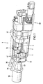
- Figure 1 illustrates the structure of an externally powered machine gun 1, in which via a breech 3, which is movable longitudinally displaceably by a continuously rotating control roller 2, not only serves to feed the cartridges 6 in a cargo space 46 (FIG. 2) of the weapon barrel 39, but according to the details in FIGS. 2 to 10 eject mechanisms shown, pushing empty cartridge cases 7 forward out of an ejection chute 35 arranged on the right or left side of the weapon barrel 39.
- a drive and gear unit 40 arranged on the rear of the machine cannon comprises the drive for the control roller 2, a stepper gear for a rotor 9, a further continuously rotating gear for the controlled feeding of the cartridges 6 via a respective insertion lever 34 and a change gear for reversing the cartridge feed, whereby a cartridge supply to the right or left of the weapon barrel according to FIGS. 9 and 10 is possible and only a sleeve ejection window 41 on the side facing away from the respective feed side of the rotor is released by a slide 36 shown in FIG. 8 for the sleeve ejection.
- the weapon housing 42 includes a breech lock 43 in the lower front area which, like the drive and transmission unit 40, is not part of this property right, but has already been adequately described in the applicant's previous property rights.
- the two ejection chutes 35 are preferably oriented slightly forward and allow the empty cartridge cases 7 to be ejected even through an armored turret cover, not shown.
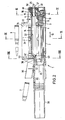
- FIG. 2 illustrates in detail the structure of the mechanisms necessary for pushing out the empty cartridge cases 7.
- the control groove 44 of the control roller 2 is designed such that the closure 3 engages in the front and rear end positions. In the front latching position, the breech 3 is locked by the breech lock 43, then the cartridge 6 is fired and the breech 3 is unlocked.
- the movement path of the cartridge case 7 held by the means 4 corresponds to the elongated tube core axis 45, so that a straight-line cartridge feed and case removal takes place is guaranteed.
- the rotor 9 arranged on a plane 24 extending transversely to the axis 26 (FIG. 3) of the control roller 2 and beyond the tube core axis 45 contains 3 pockets 8 (FIG. 3) arranged uniformly distributed over the circumference, of which the pockets 8 are located on the plane Pocket 8 occupies a position on the elongated tube core axis 45 and thereby passes the cartridge 6 to the closure 3 or the empty sleeve 7 for the sleeve transport.
- the stepping gear moves the rotor 9 one transport step further, the rotor 9 moving the empty cartridge case 7 out of the closure 3 and at the same time moving the next cartridge 6 to be fired through the subsequent pocket 8 into the closure 3.
- the sleeve slide provided as a means 5 for pushing out the empty cartridge cases 7 is mounted coaxially and longitudinally displaceably, which has driving elements 10 projecting radially into each rotor pocket 8 and is connected via a positive connection 11 to the closure 3 in such a way that it is connected on the one hand with the closure 3 is displaceable in the axial direction 12 and, on the other hand, can rotate intermittently with the rotor 9.
- the integration of the sleeve slide 5 within the rotor 9 enables its longitudinal displacement and the sliding out of the sleeve 7 in a pocket 8 of the rotor 9 facing away from the closure 3 by a driver 10 of the sleeve slide 5 which projects radially into the pockets.
- the sleeve slide 5 contains a tubular bearing housing 15 and is mounted on a drive shaft 14 arranged centrally within the rotor 9.
- a sliding or ball bearing 16 is provided within the bearing housing 15 for longitudinal displacement on the shaft 14.
- the drive shaft 14 is mounted at its front end in the weapon housing 42 and at its rear end is connected to the stepping gear in a manner not shown, and is connected via a toothed profile 47 to a drive pulley 48 firmly connected to the rotor.
- the drive pulley 48 is connected to the rotor via a thread 49 and is secured against rotation. It also serves to receive a bearing 50 for the radial and axial fixing of the rotor in the weapon housing 42.
- the shaft bearing which is fixed to the weapon housing, serves simultaneously to fasten the rotor 9.
- This front region of the bearing which belongs to the weapon housing 42, can be pivoted forwards about an axis 51 (FIG. 1) in order to carry out a simple assembly, which is why this pivoting movement is carried out the rear end walls of the two chutes are chamfered.
- the slide 36 (FIG. 8) is also arranged, which is driven in a manner not shown by the change gear.
- the weapon housing contains a front and a rear guide 52, 53 in the rotor area and insertion levers 34 for inserting the cartridge 6, which are shown in detail in FIG. 3 and will be described in detail.
- the rotor 9 has a longitudinal bore 22 on the inside for carrying out the longitudinal movement of the sleeve slide 5, which is delimited at the front by the rotor end wall and at the rear by the disk 48 and is adapted to the outer contour of the bearing housing 15.
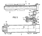
- the structure of the sleeve slide 5 in cooperation with the rotor 9 and the closure 3 will be explained in more detail with reference to Figures 3 to 7.
- the rotor 9 is equipped with three pockets 8 arranged offset by 120 ° on the circumference, into which the entrainment elements 10 of the sleeve slide, which point radially to the rotor axis 25, engage centrally in the region of the respective pocket 8 near the bottom.
- These entrainment elements 10 form the front end 19 of a longitudinal web 18 connected to the bearing housing 15 and each contain a circular segment-like entrainment surface 17 for pushing out the sleeve 7.
- Each longitudinal web 18 contains in the rear longitudinal region as an element of the positive connection 11 a circular segment-like driving spring 20 which engages in a groove 21 of the closure 3 which is adapted to the radius r of the driving spring 20 and runs in the circumferential direction 13.
- the respective chord length 1 corresponds to a groove 21 arranged on the closure 3, the width b of the driving spring 20, the length 1 and width b, however, only ensuring the positive connection 11 being greater than the dimension c of the gaps between the driving springs 20 of the sleeve slide 5.
- the rotor 9 between each pocket 8 and the bore 22 is provided with longitudinal slots 33 each adapted to the thickness s of the webs 18.
- the closure in front of and behind the groove 21 is equipped in pairs transversely to a plane 24 extending from the rotor axis 25 to the axis 26 of the control roller 2 with guide rollers 27 directed outwards on both sides, which are in the front and rear closure area are stored.
- a front and rear guide roller 27 on the left side are guided in a left-hand longitudinal guide 28 which is fastened parallel to the barrel core axis 45 and in the weapon housing 42, and correspondingly a front and rear guide roller 27 on the right side in a right-hand longitudinal guide which is fastened in the weapon housing 42 on the right hand side parallel to the barrel core axis 45 29 out.
- the guide rollers 27 have upper and lower inclined surfaces 30, preferably arranged symmetrically at 45 °, and the longitudinal guides 28, 29 have prism-shaped guide surfaces 31 corresponding to the inclined surfaces 30.
- the two longitudinal guides 28, 29 are each equipped with adjusting members 32, which are supported on the weapon housing 42, for a precise guide adjustment directed transversely to the plane 24.
- the adjusting members 32 allow the longitudinal guides 28, 29 to be adjusted from both outer sides of the breech 3.
- the flat arrangement of the roller bearings also enables reliable guidance and support of the breech and thus a largely trouble-free transmission of the forces occurring during the sleeve ejection to the weapon housing 42 furthermore, a comparatively small distance between the rotor axis 25 and the axis 26 of the control roller 2 and thus a space-saving arrangement is achieved.
- a striker 54 and a control block 55, a locking piece 56 and a compression spring 57 are also arranged on the breech 3 for igniting the cartridge 6 and for actuating the same.
- the cartridge 6 is fired in the locked state of the breech 3 by a cam (not shown) of the control groove 44 of the control roller 2, which shifts the control stone 55 in its axial direction, at the same time being displaced in the direction of the tube core axis 45 via slopes of the control stone and firing pin 54 .
- the locking piece 56 pushes the firing pin 54 back over further bevels via a bolt 58, which is displaced from an unillustrated contour of the weapon housing 42 in an elongated hole 59 of the breech 3.
- the firing pin remains under the locking piece 56 until the forward movement of the breech 3 has reached the contour of the weapon housing.
- the cartridge feed to the rotor 9 and the sleeve ejection from the rotor 9 take place via the two upper rotor lugs 8, which are arranged symmetrically on the side of the plane 24, with the feed of the cartridges 6 according to FIG. 9 optionally from the right side via an insertion lever likewise mounted on the right side in the weapon housing 34 into a right-hand rotor pocket 8 and the sleeve ejection takes place via a left-hand rotor pocket 8, while the cartridge feed according to FIG. 10 takes place in the opposite direction from the left side of the weapon by means of an insertion lever 34 mounted on the left side of the weapon housing and the sleeve ejection via the right cartridge pocket to the front.
- an insertion lever conveys a cartridge 6 into a rotor pocket 8 with each revolution, while the insertion lever 34, which is in the rest position on the other side of the weapon, through its rear contour 33 facing the pocket 8, an outer boundary wall for the sleeve 7 to be pushed out provided pocket of the rotor 9 forms.
- the insertion lever 34 has a recess 60 which interrupts its contour 33, so that only one cartridge can be conveyed via the arm 61 of the insertion lever 34 and the subsequent cartridges are blocked by the contour 33 until insertion by the arm 61.
- the slide 36 arranged between the ejection chutes 35 and the two pockets 8 provided for pushing out the sleeves 7 has laterally displaceable arms 37, 38, one arm 38 of which the way for pushing the sleeve 7 into the one ejection chute 35 releases and the other arm 37 blocks the passage to the other chute 35 and forms a front boundary wall for a new cartridge to be inserted.
- the slide 36 is displaced, for example, from one cartridge feed direction to the other shown in FIGS. 9 and 10 by a change gear, not shown.
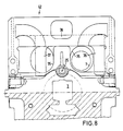
- the rotor performs the following functional steps to feed the cartridges and to eject the tubes:
- the rotor 9 is moved a further step by the step mechanism during the shooting operation in the rear latching position of the breech 3.
- the rotor 9 carries out a left-turning and in the case of a right-hand cartridge supply a clockwise rotation.
- the sleeve 7 drawn out of the closure 3 from the cargo space 45 is moved out of the closure 3 through a rotor pocket 8 and pivoted into the plane of the sleeve ejection window 41, the cartridge 6 to be supplied being pivoted into the receiving position of the closure 3 at the same time.
- a driving spring 20 of the sleeve slide 5 is unscrewed from the groove 21 of the closure 3 and a subsequent driving spring 20, which is offset by 120 °, is moved into the groove 21.
- the sleeve slide 5 is carried forward with the beginning of the closing movement via the positive connection 11.
- the driving surface 17 of the driving element 10 located on the sleeve slide 5 pushes the sleeve 7 lying in front of the sleeve slide 5 through an ejection window 41 of the weapon housing 42 and an associated ejection chute 35.
Landscapes
- Engineering & Computer Science (AREA)
- General Engineering & Computer Science (AREA)
- Portable Nailing Machines And Staplers (AREA)
- Slide Fasteners (AREA)
Applications Claiming Priority (2)
| Application Number | Priority Date | Filing Date | Title |
|---|---|---|---|
| DE19873727740 DE3727740A1 (de) | 1987-08-20 | 1987-08-20 | Vorrichtung fuer einen nach vorn gerichteten huelsenauswurf aus einer fremdgetriebenen maschinenkanone |
| DE3727740 | 1987-08-28 |
Publications (3)
| Publication Number | Publication Date |
|---|---|
| EP0303761A2 true EP0303761A2 (fr) | 1989-02-22 |
| EP0303761A3 EP0303761A3 (en) | 1989-10-18 |
| EP0303761B1 EP0303761B1 (fr) | 1992-09-09 |
Family
ID=6334107
Family Applications (1)
| Application Number | Title | Priority Date | Filing Date |
|---|---|---|---|
| EP19880103841 Expired - Lifetime EP0303761B1 (fr) | 1987-08-20 | 1988-03-11 | Dispositif pour éjecter les douilles vers l'avant dans un canon automatique à moteur externe |
Country Status (3)
| Country | Link |
|---|---|
| US (1) | US4869150A (fr) |
| EP (1) | EP0303761B1 (fr) |
| DE (2) | DE3727740A1 (fr) |
Cited By (14)
| Publication number | Priority date | Publication date | Assignee | Title |
|---|---|---|---|---|
| EP0766056A3 (fr) * | 1995-09-30 | 1998-04-15 | Rheinmetall Industrie Aktiengesellschaft | Dispositif de sécurité pour le percuteur d'une arme à feu |
| US7153820B2 (en) | 2001-08-13 | 2006-12-26 | Ecolab Inc. | Solid detergent composition and method for solidifying a detergent composition |
| US8093200B2 (en) | 2007-02-15 | 2012-01-10 | Ecolab Usa Inc. | Fast dissolving solid detergent |
| WO2012160498A2 (fr) | 2011-05-20 | 2012-11-29 | Ecolab Usa Inc. | Formulations acides destinées à être utilisées dans un système de nettoyage d'articles manufacturés |
| EP2677023A2 (fr) | 2007-10-18 | 2013-12-25 | Ecolab Inc. | Compositions nettoyantes solides, cireuses et comprimées, et leurs procédés de fabrication |
| WO2014018309A1 (fr) | 2012-07-26 | 2014-01-30 | The Procter & Gamble Company | Compositions de nettoyage liquides à faible ph et à enzymes |
| EP2792737A1 (fr) | 2011-05-20 | 2014-10-22 | Ecolab USA Inc. | Détergents sans phosphates et sans acides phosphoriques dans un système alternatif basique/acide pour le lavage de la vaisselle |
| WO2015007440A1 (fr) * | 2013-07-17 | 2015-01-22 | Rheinmetall Waffe Munition Gmbh | Dispositif d'éjection de douille et arme pourvue d'un dispositif d'éjection de douille de ce type |
| WO2015032451A1 (fr) | 2013-09-09 | 2015-03-12 | Ecolab Usa Inc. | Élimination synergique de taches par le biais d'une nouvelle combinaison de chélateurs |
| WO2015032447A1 (fr) | 2013-09-09 | 2015-03-12 | Ecolab Usa Inc. | Détachage synergique grâce à une nouvelle combinaison de chélateurs |
| EP3282004A1 (fr) | 2011-12-13 | 2018-02-14 | Ecolab USA Inc. | Procédé pour le lavage mécanique de vaisselle |
| EP3470516A1 (fr) | 2012-09-10 | 2019-04-17 | Ecolab USA Inc. | Compositions pour laver la vaisselle à la main liquides et stables contenant des enzymes |
| EP3666870A1 (fr) | 2013-10-24 | 2020-06-17 | Ecolab USA Inc. | Compositions et méthodes d'élimination des salissures des surfaces |
| WO2021022045A1 (fr) | 2019-07-31 | 2021-02-04 | Ecolab Usa Inc. | Compositions de détartrage sans équipement de protection individuelle |
Families Citing this family (8)
| Publication number | Priority date | Publication date | Assignee | Title |
|---|---|---|---|---|
| FR2664686A1 (fr) * | 1990-07-12 | 1992-01-17 | Giat Ind Sa | Dispositif d'alimentation en munitions d'une arme automatique. |
| BR9714455A (pt) | 1996-12-31 | 2000-03-21 | Procter & Gamble | e aquosas, de baixo custo com tensoativos aromáticos. |
| US6156722A (en) * | 1996-12-31 | 2000-12-05 | The Procter & Gamble Company | Laundry detergent compositions comprising dye fixatives |
| BR9714194A (pt) * | 1996-12-31 | 2000-03-28 | Procter & Gamble | Composições detergentes para a lavagem de tecidos com poliamidas-poliaminas para proporcionar benefìcios na aparência aos tecidos lavados com as memas |
| BE1012500A3 (fr) * | 1999-03-04 | 2000-11-07 | Fn Herstal Sa | Arme a feu avec ejection vers l'avant ou reportee vers l'avant de l'arme. |
| TW201130553A (en) * | 2010-03-08 | 2011-09-16 | yi-rong Li | Transmission method of toy gun and transmission mechanism thereof |
| CN103822533B (zh) * | 2014-03-10 | 2016-03-16 | 宋益伶 | 弹性变向抛壳机构 |
| CN114812265B (zh) * | 2022-04-28 | 2025-07-22 | 北京天航创联科技发展有限责任公司 | 子弹顺位装置和装弹装置 |
Family Cites Families (9)
| Publication number | Priority date | Publication date | Assignee | Title |
|---|---|---|---|---|
| US3894471A (en) * | 1971-09-30 | 1975-07-15 | Pacific Car & Foundry Co | Rapid fire weapon for turret installation |
| US4373422A (en) * | 1978-09-29 | 1983-02-15 | Ford Motor Company | Reciprocating feed system |
| US4269108A (en) * | 1979-03-27 | 1981-05-26 | Ares, Inc. | Programmed shell casing ejector apparatus for automatic cannon |
| US4348938A (en) * | 1979-10-30 | 1982-09-14 | Ares, Inc. | Two stage shell feeding apparatus with shell feeding path control |
| US4563936A (en) * | 1982-05-28 | 1986-01-14 | Hughes Helicopters, Inc. | Weapon with next round select feed system |
| US4612843A (en) * | 1983-06-03 | 1986-09-23 | Etat Francais | Dual ammunition feed for automatic weapons |
| FR2547042B1 (fr) * | 1983-06-03 | 1985-07-12 | France Etat Armement | Double alimentation en munitions pour armes automatiques |
| FR2579743B1 (fr) * | 1985-03-26 | 1987-05-15 | France Etat Armement | Arme automatique a moteur externe |
| US4700608A (en) * | 1985-10-30 | 1987-10-20 | General Electric Company | Machine gun |
-
1987
- 1987-08-20 DE DE19873727740 patent/DE3727740A1/de not_active Withdrawn
-
1988
- 1988-03-11 DE DE8888103841T patent/DE3874461D1/de not_active Expired - Fee Related
- 1988-03-11 EP EP19880103841 patent/EP0303761B1/fr not_active Expired - Lifetime
- 1988-08-26 US US07/237,672 patent/US4869150A/en not_active Expired - Lifetime
Cited By (27)
| Publication number | Priority date | Publication date | Assignee | Title |
|---|---|---|---|---|
| EP0766056A3 (fr) * | 1995-09-30 | 1998-04-15 | Rheinmetall Industrie Aktiengesellschaft | Dispositif de sécurité pour le percuteur d'une arme à feu |
| US7153820B2 (en) | 2001-08-13 | 2006-12-26 | Ecolab Inc. | Solid detergent composition and method for solidifying a detergent composition |
| US10005986B2 (en) | 2007-02-15 | 2018-06-26 | Ecolab Usa Inc. | Fast dissolving solid detergent |
| US8093200B2 (en) | 2007-02-15 | 2012-01-10 | Ecolab Usa Inc. | Fast dissolving solid detergent |
| US8309509B2 (en) | 2007-02-15 | 2012-11-13 | Ecolab Usa Inc. | Fast dissolving solid detergent |
| US11261406B2 (en) | 2007-02-15 | 2022-03-01 | Ecolab Usa Inc. | Fast dissolving solid detergent |
| EP2617804A1 (fr) | 2007-02-15 | 2013-07-24 | Ecolab Inc. | Détergent solide se dissolvant rapidement |
| US10577565B2 (en) | 2007-02-15 | 2020-03-03 | Ecolab Usa Inc. | Fast dissolving solid detergent |
| US8697625B2 (en) | 2007-02-15 | 2014-04-15 | Ecolab Usa Inc. | Fast dissolving solid detergent |
| EP3339412A1 (fr) | 2007-02-15 | 2018-06-27 | Ecolab Usa Inc. | Détergent solide à dissolution rapide |
| EP2677023A2 (fr) | 2007-10-18 | 2013-12-25 | Ecolab Inc. | Compositions nettoyantes solides, cireuses et comprimées, et leurs procédés de fabrication |
| EP3438235A1 (fr) | 2007-10-18 | 2019-02-06 | Ecolab USA Inc. | Compositions de nettoyage à presse, cire et solide et leurs procédés de fabrication |
| WO2012160498A2 (fr) | 2011-05-20 | 2012-11-29 | Ecolab Usa Inc. | Formulations acides destinées à être utilisées dans un système de nettoyage d'articles manufacturés |
| EP2902471A1 (fr) | 2011-05-20 | 2015-08-05 | Ecolab USA Inc. | Détergents sans phosphates et acides non phosphoriques dans un système alternatif alcalin/acide pour le lavage de la vaisselle |
| EP2792737A1 (fr) | 2011-05-20 | 2014-10-22 | Ecolab USA Inc. | Détergents sans phosphates et sans acides phosphoriques dans un système alternatif basique/acide pour le lavage de la vaisselle |
| EP3282004A1 (fr) | 2011-12-13 | 2018-02-14 | Ecolab USA Inc. | Procédé pour le lavage mécanique de vaisselle |
| WO2014018309A1 (fr) | 2012-07-26 | 2014-01-30 | The Procter & Gamble Company | Compositions de nettoyage liquides à faible ph et à enzymes |
| EP3470516A1 (fr) | 2012-09-10 | 2019-04-17 | Ecolab USA Inc. | Compositions pour laver la vaisselle à la main liquides et stables contenant des enzymes |
| WO2015007440A1 (fr) * | 2013-07-17 | 2015-01-22 | Rheinmetall Waffe Munition Gmbh | Dispositif d'éjection de douille et arme pourvue d'un dispositif d'éjection de douille de ce type |
| EP3279304A1 (fr) | 2013-09-09 | 2018-02-07 | Ecolab USA Inc. | Élimination synergique de taches par le biais d'une nouvelle combinaison de chélateurs |
| WO2015032451A1 (fr) | 2013-09-09 | 2015-03-12 | Ecolab Usa Inc. | Élimination synergique de taches par le biais d'une nouvelle combinaison de chélateurs |
| EP3561034A1 (fr) | 2013-09-09 | 2019-10-30 | Ecolab USA Inc. | Élimination synergique de taches par le biais d'une nouvelle combinaison de chélateurs |
| EP3272847A1 (fr) | 2013-09-09 | 2018-01-24 | Ecolab USA Inc. | Élimination synergique de taches par le biais d'une nouvelle combinaison de chélateurs |
| WO2015032447A1 (fr) | 2013-09-09 | 2015-03-12 | Ecolab Usa Inc. | Détachage synergique grâce à une nouvelle combinaison de chélateurs |
| EP3666870A1 (fr) | 2013-10-24 | 2020-06-17 | Ecolab USA Inc. | Compositions et méthodes d'élimination des salissures des surfaces |
| EP4276163A1 (fr) | 2013-10-24 | 2023-11-15 | Ecolab USA Inc. | Compositions et méthodes d'élimination des salissures des surfaces |
| WO2021022045A1 (fr) | 2019-07-31 | 2021-02-04 | Ecolab Usa Inc. | Compositions de détartrage sans équipement de protection individuelle |
Also Published As
| Publication number | Publication date |
|---|---|
| DE3727740A1 (de) | 1989-03-02 |
| EP0303761B1 (fr) | 1992-09-09 |
| US4869150A (en) | 1989-09-26 |
| EP0303761A3 (en) | 1989-10-18 |
| DE3874461D1 (de) | 1992-10-15 |
Similar Documents
| Publication | Publication Date | Title |
|---|---|---|
| EP0303761B1 (fr) | Dispositif pour éjecter les douilles vers l'avant dans un canon automatique à moteur externe | |
| DE68917396T2 (de) | Vorrichtung zum Öffnen und Schliessen eines Verschlusses in halbautomatischen Pistolen. | |
| DE2752721C2 (de) | Verschlußblockanordnung für eine automatische Schußwaffe | |
| EP0004581A2 (fr) | Arme portative automatique | |
| EP0103219B1 (fr) | Chargeur à étoupilles d'allumage pour une culasse à coin dans un canon | |
| DE3712905A1 (de) | Maschinenwaffe mit schusskontrolle | |
| DE1428787B1 (de) | Zufuehrvorrichtung fuer eine selbsttaetige Feuerwaffe | |
| DE2751042C2 (de) | Gasdruckladeeinrichtung für eine selbstladende Schußwaffe | |
| DE3218550C2 (de) | Maschinenkanone | |
| DE1960023C1 (de) | Automatische Waffe zum Abfeuern von Patronen | |
| DE2446145C2 (de) | Munitionszubringer für eine Waffe mit in Waffenlängsrichtung hin- und herbewegtem Verschluß | |
| DE3023957C2 (de) | Wechselgurtzuführer für eine selbsttätige Feuerwaffe, insbesondere Maschinenkanone | |
| DE2044964C3 (de) | Automatische Schnellfeuerwaffe mit Stützriegelverschluß | |
| DE3521800A1 (de) | Lauf-wechselsystem fuer eine pistole | |
| EP0124072A2 (fr) | Dispositif pour arrêter rapidement un canon automatique à moteur externe | |
| DE3432537C2 (de) | Repetiergewehrverschluß | |
| DE3903823A1 (de) | Revolver mit tiefliegendem lauf | |
| EP1469273B1 (fr) | Culasse à coin | |
| DE3238725C2 (fr) | ||
| DE3427875C1 (de) | Automatische Feuerwaffe mit walzenfoermigem Verschlussteil | |
| EP0185191B1 (fr) | Dispositif de déchargement pour un canon à moteur externe | |
| DE1264294B (de) | Verschluss fuer Handfeuerwaffen | |
| EP0123059B1 (fr) | Pistolet de signalisation | |
| DE69313176T2 (de) | Einrichtung zum Laden von Munition in einem schwenkbaren Patronenlager | |
| EP0419523A1 (fr) | Arme a feu a chargement automatique |
Legal Events
| Date | Code | Title | Description |
|---|---|---|---|
| PUAI | Public reference made under article 153(3) epc to a published international application that has entered the european phase |
Free format text: ORIGINAL CODE: 0009012 |
|
| AK | Designated contracting states |
Kind code of ref document: A2 Designated state(s): CH DE FR GB IT LI |
|
| PUAL | Search report despatched |
Free format text: ORIGINAL CODE: 0009013 |
|
| AK | Designated contracting states |
Kind code of ref document: A3 Designated state(s): CH DE FR GB IT LI |
|
| 17P | Request for examination filed |
Effective date: 19890902 |
|
| 17Q | First examination report despatched |
Effective date: 19910319 |
|
| ITF | It: translation for a ep patent filed | ||
| GRAA | (expected) grant |
Free format text: ORIGINAL CODE: 0009210 |
|
| AK | Designated contracting states |
Kind code of ref document: B1 Designated state(s): CH DE FR GB IT LI |
|
| REF | Corresponds to: |
Ref document number: 3874461 Country of ref document: DE Date of ref document: 19921015 |
|
| GBT | Gb: translation of ep patent filed (gb section 77(6)(a)/1977) | ||
| ET | Fr: translation filed | ||
| REG | Reference to a national code |
Ref country code: CH Ref legal event code: PFA Free format text: RHEINMETALL GMBH |
|
| RAP4 | Party data changed (patent owner data changed or rights of a patent transferred) |
Owner name: RHEINMETALL GMBH |
|
| PLBE | No opposition filed within time limit |
Free format text: ORIGINAL CODE: 0009261 |
|
| STAA | Information on the status of an ep patent application or granted ep patent |
Free format text: STATUS: NO OPPOSITION FILED WITHIN TIME LIMIT |
|
| 26N | No opposition filed | ||
| PGFP | Annual fee paid to national office [announced via postgrant information from national office to epo] |
Ref country code: CH Payment date: 20000221 Year of fee payment: 13 |
|
| PG25 | Lapsed in a contracting state [announced via postgrant information from national office to epo] |
Ref country code: LI Free format text: LAPSE BECAUSE OF NON-PAYMENT OF DUE FEES Effective date: 20010331 Ref country code: CH Free format text: LAPSE BECAUSE OF NON-PAYMENT OF DUE FEES Effective date: 20010331 |
|
| REG | Reference to a national code |
Ref country code: CH Ref legal event code: PL |
|
| REG | Reference to a national code |
Ref country code: GB Ref legal event code: IF02 |
|
| PGFP | Annual fee paid to national office [announced via postgrant information from national office to epo] |
Ref country code: GB Payment date: 20040303 Year of fee payment: 17 |
|
| PGFP | Annual fee paid to national office [announced via postgrant information from national office to epo] |
Ref country code: DE Payment date: 20040305 Year of fee payment: 17 |
|
| PGFP | Annual fee paid to national office [announced via postgrant information from national office to epo] |
Ref country code: FR Payment date: 20040310 Year of fee payment: 17 |
|
| PG25 | Lapsed in a contracting state [announced via postgrant information from national office to epo] |
Ref country code: IT Free format text: LAPSE BECAUSE OF NON-PAYMENT OF DUE FEES;WARNING: LAPSES OF ITALIAN PATENTS WITH EFFECTIVE DATE BEFORE 2007 MAY HAVE OCCURRED AT ANY TIME BEFORE 2007. THE CORRECT EFFECTIVE DATE MAY BE DIFFERENT FROM THE ONE RECORDED. Effective date: 20050311 Ref country code: GB Free format text: LAPSE BECAUSE OF NON-PAYMENT OF DUE FEES Effective date: 20050311 |
|
| PG25 | Lapsed in a contracting state [announced via postgrant information from national office to epo] |
Ref country code: DE Free format text: LAPSE BECAUSE OF NON-PAYMENT OF DUE FEES Effective date: 20051001 |
|
| GBPC | Gb: european patent ceased through non-payment of renewal fee |
Effective date: 20050311 |
|
| PG25 | Lapsed in a contracting state [announced via postgrant information from national office to epo] |
Ref country code: FR Free format text: LAPSE BECAUSE OF NON-PAYMENT OF DUE FEES Effective date: 20051130 |
|
| REG | Reference to a national code |
Ref country code: FR Ref legal event code: ST Effective date: 20051130 |