EP0303766A2 - Dispositif pour le nettoiement d'une liaison de contact - Google Patents
Dispositif pour le nettoiement d'une liaison de contact Download PDFInfo
- Publication number
- EP0303766A2 EP0303766A2 EP88106312A EP88106312A EP0303766A2 EP 0303766 A2 EP0303766 A2 EP 0303766A2 EP 88106312 A EP88106312 A EP 88106312A EP 88106312 A EP88106312 A EP 88106312A EP 0303766 A2 EP0303766 A2 EP 0303766A2
- Authority
- EP
- European Patent Office
- Prior art keywords
- handset
- base station
- contact
- contact pins
- guide
- Prior art date
- Legal status (The legal status is an assumption and is not a legal conclusion. Google has not performed a legal analysis and makes no representation as to the accuracy of the status listed.)
- Granted
Links
Images

Classifications
-
- H—ELECTRICITY
- H04—ELECTRIC COMMUNICATION TECHNIQUE
- H04M—TELEPHONIC COMMUNICATION
- H04M1/00—Substation equipment, e.g. for use by subscribers
- H04M1/02—Constructional features of telephone sets
- H04M1/04—Supports for telephone transmitters or receivers
- H04M1/06—Hooks; Cradles
-
- H—ELECTRICITY
- H02—GENERATION; CONVERSION OR DISTRIBUTION OF ELECTRIC POWER
- H02J—ELECTRIC POWER NETWORKS; CIRCUIT ARRANGEMENTS OR SYSTEMS FOR SUPPLYING OR DISTRIBUTING ELECTRIC POWER; SYSTEMS FOR STORING ELECTRIC ENERGY
- H02J7/00—Circuit arrangements for charging or discharging batteries or for supplying loads from batteries
- H02J7/70—Circuit arrangements for charging or discharging batteries or for supplying loads from batteries characterised by the mechanical construction
- H02J7/731—Circuit arrangements for charging or discharging batteries or for supplying loads from batteries characterised by the mechanical construction specially adapted for holding portable devices containing batteries
-
- H—ELECTRICITY
- H02—GENERATION; CONVERSION OR DISTRIBUTION OF ELECTRIC POWER
- H02J—ELECTRIC POWER NETWORKS; CIRCUIT ARRANGEMENTS OR SYSTEMS FOR SUPPLYING OR DISTRIBUTING ELECTRIC POWER; SYSTEMS FOR STORING ELECTRIC ENERGY
- H02J7/00—Circuit arrangements for charging or discharging batteries or for supplying loads from batteries
- H02J7/70—Circuit arrangements for charging or discharging batteries or for supplying loads from batteries characterised by the mechanical construction
- H02J7/751—Circuit arrangements for charging or discharging batteries or for supplying loads from batteries characterised by the mechanical construction concerning the insertion or the connection of the batteries
Definitions
- the invention relates to a device for automatically cleaning a releasable contact connection of electrical contacts which are actuated when a handset is placed or attached to or on a base station of a wireless telephone set, the handset consisting essentially of a lower and upper part with an interposed printed circuit board, an auditory and speech capsule, a keypad and a battery drawer.
- Detachable contact connections are known in which a self-cleaning contact system of electrical contacts is achieved by sliding two contact parts against one another (Plug connections). It is also known in a wireless telephone set that when the handset is placed on the assigned base station, a charging contact connection is made between a rechargeable battery pack in the handset and the base station. This is done through a static contact connection. Oxidation and contamination of the contacts in a detachable contact connection of the type described can only be avoided if the contacts come into constant contact with a certain contact pressure at the same contact point. In order to ensure such a condition, very precise guidance of the handset through the base station is required when hanging up. In practice, however, it has been shown that by placing the handset on the base station differently, the user does not always have a secure and co-located contact system for the contact connection parts.
- the object of the invention is therefore to provide a device for making electrical contact with a handset when it is placed on a wireless telephone set for charging the batteries in the handset, in which the handset inevitably assumes its end position when it is placed on the base station, while at the same time ensuring that it is perfectly safe establishes electrical contact connection to the base station.
- a guide between the handset and the base station is provided for this purpose, which inevitably brings the handset into an end position due to its own weight when it is placed on the base station, and the Contact points of the contact connections are designed as sliding contacts. As a result, the contact points are cleaned both when hanging up and when removing the handset.
- the handset shows a wireless telephone set 1 which is formed from a handset 2 and a base station 3.
- the handset consists essentially of an upper part 4 and a lower part 5 with an intermediate circuit board, which carries the components, and a hearing and speaking capsule, not shown, a keypad and a battery insert.
- the handset is connected to the base station via a detachable contact connection for charging the battery pack located in the handset.
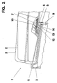
- FIG. 2 shows an enlarged view of a partial view of FIG. 1 and the area of the contact connection.
- the contact connection consists of two contact pins 6 arranged next to one another, which are assigned to the ground station, and of two strip-shaped contact tracks 7 opposite the contact pins, which are located in the handset. Both contact pins are movable and stored in guide bores under constant spring tension.
- the pins have a contact tip and have a stepped shaft on which a compression spring 8 is pushed.
- the spring stroke of the contact pins is limited by a locking washer 9.
- the contact tracks are provided with a solder tab 10. 2, the drawing shows the handset in two positions. The handset is shown once in its end position after sliding onto the base station 3 and secondly when it is placed on the base station.
- the handset When placing on the base station, the handset inevitably comes into contact with an inclined sliding surface 11, which is located at the base station.
- the inevitable sliding of the handset on the base station is essentially given in that the base station in the contact area 6, 7 has a guide lug 12 with an inwardly directed inclined surface 13 and that Handset with a bead-like projection 14 opposite the inclined surface inevitably engages under the guide lug 12 of the base station when it is placed on or attached to or on the base station.
- the dead weight and a predetermined guidance of the handset to the base station thus ensure that when the end position is reached, the contact pins 6 slide along the strip-shaped contact tracks 7 with increasing pressure increase.
- the contact connection between the handset and the base station is inevitably subjected to a constant cleaning process.
Landscapes
- Engineering & Computer Science (AREA)
- Power Engineering (AREA)
- Signal Processing (AREA)
- Telephone Set Structure (AREA)
- Coupling Device And Connection With Printed Circuit (AREA)
- Push-Button Switches (AREA)
- Electrical Discharge Machining, Electrochemical Machining, And Combined Machining (AREA)
Priority Applications (1)
| Application Number | Priority Date | Filing Date | Title |
|---|---|---|---|
| AT88106312T ATE91209T1 (de) | 1987-08-21 | 1988-04-20 | Einrichtung zum reinigen einer kontaktverbindung. |
Applications Claiming Priority (2)
| Application Number | Priority Date | Filing Date | Title |
|---|---|---|---|
| DE3727934 | 1987-08-21 | ||
| DE19873727934 DE3727934A1 (de) | 1987-08-21 | 1987-08-21 | Einrichtung zum reinigen einer kontaktverbindung |
Publications (3)
| Publication Number | Publication Date |
|---|---|
| EP0303766A2 true EP0303766A2 (fr) | 1989-02-22 |
| EP0303766A3 EP0303766A3 (en) | 1989-11-23 |
| EP0303766B1 EP0303766B1 (fr) | 1993-06-30 |
Family
ID=6334207
Family Applications (1)
| Application Number | Title | Priority Date | Filing Date |
|---|---|---|---|
| EP88106312A Expired - Lifetime EP0303766B1 (fr) | 1987-08-21 | 1988-04-20 | Dispositif pour le nettoiement d'une liaison de contact |
Country Status (3)
| Country | Link |
|---|---|
| EP (1) | EP0303766B1 (fr) |
| AT (1) | ATE91209T1 (fr) |
| DE (2) | DE3727934A1 (fr) |
Cited By (2)
| Publication number | Priority date | Publication date | Assignee | Title |
|---|---|---|---|---|
| US5557970A (en) * | 1994-01-10 | 1996-09-24 | The United States Of America As Represented By The Secretary Of The Army | Automated thickness measurement system |
| WO2005000114A3 (fr) * | 2003-06-03 | 2005-06-09 | Bayer Healthcare Llc | Appareil de diagnostic medical portatif |
Family Cites Families (4)
| Publication number | Priority date | Publication date | Assignee | Title |
|---|---|---|---|---|
| US4731813A (en) * | 1983-12-30 | 1988-03-15 | Motorola, Inc. | Address encoding system for portable battery-operated devices |
| DE3400294A1 (de) * | 1984-01-05 | 1985-07-18 | Siemens AG, 1000 Berlin und 8000 München | Station zur aufnahme eines aufladbaren, schnurlosen telefons |
| US4581498A (en) * | 1984-03-08 | 1986-04-08 | Transworld Drilling Company | Reel having a removable hub |
| US4560223A (en) * | 1984-06-29 | 1985-12-24 | Pylon Company, Inc. | Self-cleaning tri-cusp signal contact |
-
1987
- 1987-08-21 DE DE19873727934 patent/DE3727934A1/de not_active Withdrawn
-
1988
- 1988-04-20 DE DE8888106312T patent/DE3882102D1/de not_active Expired - Lifetime
- 1988-04-20 AT AT88106312T patent/ATE91209T1/de not_active IP Right Cessation
- 1988-04-20 EP EP88106312A patent/EP0303766B1/fr not_active Expired - Lifetime
Cited By (2)
| Publication number | Priority date | Publication date | Assignee | Title |
|---|---|---|---|---|
| US5557970A (en) * | 1994-01-10 | 1996-09-24 | The United States Of America As Represented By The Secretary Of The Army | Automated thickness measurement system |
| WO2005000114A3 (fr) * | 2003-06-03 | 2005-06-09 | Bayer Healthcare Llc | Appareil de diagnostic medical portatif |
Also Published As
| Publication number | Publication date |
|---|---|
| DE3882102D1 (de) | 1993-08-05 |
| EP0303766B1 (fr) | 1993-06-30 |
| DE3727934A1 (de) | 1989-03-02 |
| ATE91209T1 (de) | 1993-07-15 |
| EP0303766A3 (en) | 1989-11-23 |
Similar Documents
| Publication | Publication Date | Title |
|---|---|---|
| DE68929505T2 (de) | Kleines wiederaufladbares elektrisches Gerät | |
| DE2515171A1 (de) | Vorrichtung zum gleichzeitigen einfuehren mehrerer elektrischer leiter in anschlussglieder eines elektrischen verbinders | |
| DE1025035B (de) | Verfahren zum Herstellen einer loesbaren elektrischen Verbindung zwischen einem Leiter und einem Klemmteil unter Verwendung eines federnden Verbinders sowie Montagewerkzeug zur Durchfuehrung des Verfahrens | |
| DE2360822A1 (de) | Halterung fuer sicherungspatronen | |
| DE3424971C2 (de) | Halte- und Transportvorrichtung für bedrahtete Schaltungselemente mit unterschiedlichem Rastermaß | |
| EP0303766A2 (fr) | Dispositif pour le nettoiement d'une liaison de contact | |
| DE2228780A1 (de) | Zugentlastungsanordnung fuer einer steckerleiste zugefuehrte kabel | |
| DE3877729T2 (de) | Anordnung zum erzielen einer kontaktfunktion in einem pruefsystem fuer relaisschutzausruestungen. | |
| DE3708782A1 (de) | Vorrichtung zum kontaktieren und ggf. einkuerzen von isolierten kabeladern | |
| DE60121754T2 (de) | Batteriehalter mit integriertem schalter | |
| DE10005791A1 (de) | Station für ein schnurloses Telekommunikationsendgerät | |
| DE2710260C3 (de) | Klemmhalterung für Rundbatterien | |
| DE3407446A1 (de) | Steckerkupplung mit steckersicherung | |
| DE946364C (de) | Steckkontakteinrichtung mit festen und zurueckfedernden Kontaktstiften | |
| DE4425550A1 (de) | Anordnung mit elektrischer Fassung und Abdeckeinrichtung | |
| DE1948041C3 (de) | Anschlußvorrichtung | |
| DE2426208C3 (de) | Vorrichtung zur Halterung einer Batterie | |
| DE1124558B (de) | Gestellrahmenaufbau fuer Fernmelde-, insbesondere Fernsprechanlagen | |
| DE3425541A1 (de) | Fernsprechstation mit ablage fuer den handapparat | |
| DE1765802C (de) | Kontaktelement | |
| DE2441699A1 (de) | Vorrichtung zum halten von aufdrucken od. dgl. aufweisenden anzeigetraegern, insbesondere fluessigkristallanzeigen | |
| DE8804264U1 (de) | Vorrichtung zur Überführung eines Teststreifens von einer ersten Unterlage zu einer zweiten Unterlage | |
| DE1274710B (de) | Verbindungsklemme | |
| DE1813062A1 (de) | Verfahren und Vorrichtung zum Bestuecken gedruckter Schaltungen | |
| DE4001412A1 (de) | Schnurloses telefon |
Legal Events
| Date | Code | Title | Description |
|---|---|---|---|
| PUAI | Public reference made under article 153(3) epc to a published international application that has entered the european phase |
Free format text: ORIGINAL CODE: 0009012 |
|
| AK | Designated contracting states |
Kind code of ref document: A2 Designated state(s): AT BE CH DE FR GB IT LI |
|
| PUAL | Search report despatched |
Free format text: ORIGINAL CODE: 0009013 |
|
| AK | Designated contracting states |
Kind code of ref document: A3 Designated state(s): AT BE CH DE FR GB IT LI |
|
| RHK1 | Main classification (correction) |
Ipc: H04M 1/72 |
|
| 17P | Request for examination filed |
Effective date: 19900223 |
|
| 17Q | First examination report despatched |
Effective date: 19920122 |
|
| GRAA | (expected) grant |
Free format text: ORIGINAL CODE: 0009210 |
|
| AK | Designated contracting states |
Kind code of ref document: B1 Designated state(s): AT BE CH DE FR GB IT LI |
|
| REF | Corresponds to: |
Ref document number: 91209 Country of ref document: AT Date of ref document: 19930715 Kind code of ref document: T |
|
| REF | Corresponds to: |
Ref document number: 3882102 Country of ref document: DE Date of ref document: 19930805 |
|
| GBT | Gb: translation of ep patent filed (gb section 77(6)(a)/1977) |
Effective date: 19930708 |
|
| ET | Fr: translation filed | ||
| ITF | It: translation for a ep patent filed | ||
| PLBE | No opposition filed within time limit |
Free format text: ORIGINAL CODE: 0009261 |
|
| REG | Reference to a national code |
Ref country code: GB Ref legal event code: 746 Effective date: 19940512 |
|
| ITPR | It: changes in ownership of a european patent |
Owner name: OFFERTA DI LICENZA AL PUBBLICO |
|
| 26N | No opposition filed | ||
| REG | Reference to a national code |
Ref country code: FR Ref legal event code: DL |
|
| REG | Reference to a national code |
Ref country code: CH Ref legal event code: PFA Free format text: GRUNDIG E.M.V. ELEKTRO- MECHANISCHE VERSUCHSANSTALT MAX GRUNDIG GMBH & CO. KG |
|
| PLAA | Information modified related to event that no opposition was filed |
Free format text: ORIGINAL CODE: 0009299DELT |
|
| PLBE | No opposition filed within time limit |
Free format text: ORIGINAL CODE: 0009261 |
|
| STAA | Information on the status of an ep patent application or granted ep patent |
Free format text: STATUS: NO OPPOSITION FILED WITHIN TIME LIMIT |
|
| 26N | No opposition filed | ||
| RAP2 | Party data changed (patent owner data changed or rights of a patent transferred) |
Owner name: GRUNDIG E.M.V. ELEKTRO-MECHANISCHE VERSUCHSANSTALT |
|
| REG | Reference to a national code |
Ref country code: FR Ref legal event code: CD |
|
| PGFP | Annual fee paid to national office [announced via postgrant information from national office to epo] |
Ref country code: BE Payment date: 19970314 Year of fee payment: 10 |
|
| PGFP | Annual fee paid to national office [announced via postgrant information from national office to epo] |
Ref country code: CH Payment date: 19970409 Year of fee payment: 10 |
|
| PGFP | Annual fee paid to national office [announced via postgrant information from national office to epo] |
Ref country code: AT Payment date: 19970430 Year of fee payment: 10 |
|
| REG | Reference to a national code |
Ref country code: CH Ref legal event code: PFA Free format text: GRUNDIG E.M.V. ELEKTRO- MECHANISCHE VERSUCHSANSTALT MAX GRUNDIG GMBH & CO. KG TRANSFER- GRUNDIG AG |
|
| REG | Reference to a national code |
Ref country code: GB Ref legal event code: 732E |
|
| PG25 | Lapsed in a contracting state [announced via postgrant information from national office to epo] |
Ref country code: AT Free format text: LAPSE BECAUSE OF NON-PAYMENT OF DUE FEES Effective date: 19980420 |
|
| PG25 | Lapsed in a contracting state [announced via postgrant information from national office to epo] |
Ref country code: BE Free format text: LAPSE BECAUSE OF NON-PAYMENT OF DUE FEES Effective date: 19980430 Ref country code: LI Free format text: LAPSE BECAUSE OF NON-PAYMENT OF DUE FEES Effective date: 19980430 Ref country code: CH Free format text: LAPSE BECAUSE OF NON-PAYMENT OF DUE FEES Effective date: 19980430 |
|
| REG | Reference to a national code |
Ref country code: FR Ref legal event code: TP |
|
| BERE | Be: lapsed |
Owner name: GRUNDIG A.G. Effective date: 19980430 |
|
| REG | Reference to a national code |
Ref country code: CH Ref legal event code: PL |
|
| REG | Reference to a national code |
Ref country code: GB Ref legal event code: IF02 |
|
| REG | Reference to a national code |
Ref country code: GB Ref legal event code: 732E |
|
| REG | Reference to a national code |
Ref country code: FR Ref legal event code: TP |
|
| PG25 | Lapsed in a contracting state [announced via postgrant information from national office to epo] |
Ref country code: IT Free format text: LAPSE BECAUSE OF NON-PAYMENT OF DUE FEES;WARNING: LAPSES OF ITALIAN PATENTS WITH EFFECTIVE DATE BEFORE 2007 MAY HAVE OCCURRED AT ANY TIME BEFORE 2007. THE CORRECT EFFECTIVE DATE MAY BE DIFFERENT FROM THE ONE RECORDED. Effective date: 20050420 |
|
| PGFP | Annual fee paid to national office [announced via postgrant information from national office to epo] |
Ref country code: DE Payment date: 20070509 Year of fee payment: 20 |
|
| PGFP | Annual fee paid to national office [announced via postgrant information from national office to epo] |
Ref country code: GB Payment date: 20070419 Year of fee payment: 20 |
|
| PGFP | Annual fee paid to national office [announced via postgrant information from national office to epo] |
Ref country code: FR Payment date: 20070413 Year of fee payment: 20 |
|
| REG | Reference to a national code |
Ref country code: GB Ref legal event code: PE20 Expiry date: 20080419 |
|
| PG25 | Lapsed in a contracting state [announced via postgrant information from national office to epo] |
Ref country code: GB Free format text: LAPSE BECAUSE OF EXPIRATION OF PROTECTION Effective date: 20080419 |