EP0303801B2 - Absperrarmatur - Google Patents
Absperrarmatur Download PDFInfo
- Publication number
- EP0303801B2 EP0303801B2 EP88110035A EP88110035A EP0303801B2 EP 0303801 B2 EP0303801 B2 EP 0303801B2 EP 88110035 A EP88110035 A EP 88110035A EP 88110035 A EP88110035 A EP 88110035A EP 0303801 B2 EP0303801 B2 EP 0303801B2
- Authority
- EP
- European Patent Office
- Prior art keywords
- valve
- shut
- valve rod
- spindle
- thread
- Prior art date
- Legal status (The legal status is an assumption and is not a legal conclusion. Google has not performed a legal analysis and makes no representation as to the accuracy of the status listed.)
- Expired - Lifetime
Links
Images
Classifications
-
- F—MECHANICAL ENGINEERING; LIGHTING; HEATING; WEAPONS; BLASTING
- F16—ENGINEERING ELEMENTS AND UNITS; GENERAL MEASURES FOR PRODUCING AND MAINTAINING EFFECTIVE FUNCTIONING OF MACHINES OR INSTALLATIONS; THERMAL INSULATION IN GENERAL
- F16K—VALVES; TAPS; COCKS; ACTUATING-FLOATS; DEVICES FOR VENTING OR AERATING
- F16K31/00—Actuating devices; Operating means; Releasing devices
- F16K31/02—Actuating devices; Operating means; Releasing devices electric; magnetic
- F16K31/04—Actuating devices; Operating means; Releasing devices electric; magnetic using a motor
- F16K31/047—Actuating devices; Operating means; Releasing devices electric; magnetic using a motor characterised by mechanical means between the motor and the valve, e.g. lost motion means reducing backlash, clutches, brakes or return means
Definitions
- the invention relates to a shut-off valve with a drive device and with a threaded spindle, to which a fitting plate which can be placed on a seat is formed, a spindle nut being in engagement with the spindle and the drive device being arranged directly connected to the spindle nut.
- Shut-off valves are generally known. They are usually connected to a drive device.
- a known drive device which serves as an actuator for a valve, has an electric motor which drives a drive bushing, for example a shaft, via a gear.
- the drive bush is in turn engaged with the valve nut of the valve and sets it in rotation. The rotation movement is converted into an axial movement of the spindle and thus of the valve plate by means of a thread on the spindle and on the spindle nut.
- a drive for valves is known from DE-B-1 185 031, a worm wheel being connected to the spindle of the closure piece and being in engagement with a motor-driven worm spindle.
- the efficiency of the known conversion from a rotary movement into an axial movement is less than 50%, generally only between 25% and 35%.
- the overall efficiency of a known combination of drive device and shut-off valve, connected by a drive bushing, is only between 10% and 25%. This makes a very high output of an electric motor in the drive device necessary. When determining the required drive power, it must always be taken into account that the very large proportion of 65% to 75% of the total drive power cannot be used to advantage due to friction.
- the proportion of friction during operation of the valve is subject to changes that are caused by different temperatures or, for example, can be attributed to contamination after long periods of inactivity.
- the fluctuations in the friction have a major influence on the actuating force of the valve.
- the invention had for its object to develop a shut-off valve which takes up little space, which also achieves good overall efficiency due to low friction losses with a relatively low power of the electric motor and which enables actuating forces to be clearly determined by a low friction component.
- shut-off valve according to the invention With the shut-off valve according to the invention, the advantage is achieved that the thread of the spindle causes little friction due to the lack of self-locking and nevertheless cannot be moved by the flowing medium due to the existing brake.
- the shut-off valve according to the invention achieves a high overall efficiency, so that a comparatively small drive device can be used.
- the shut-off valve according to the invention therefore requires little space.
- shut-off valve according to the invention there is a valve that combines the drive device and the shut-off device into one system.
- the number of components required and the overall height of the shut-off valve according to the invention are considerably lower than in most known valves with the same nominal size.
- Shut-off valves constructed according to the invention can be used particularly advantageously in power plants, since there is little space available there.
- the thread of the spindle has a large pitch that is greater than 5 °. With such a pitch it is ensured that the thread has no self-locking. Due to the translation of the relatively steep thread of the spindle, the proportion of friction in the required drive power is low. This leads to an increase in the overall efficiency.
- a brake on the drive device consists, for example, of a gearwheel which is connected to the spindle nut and of a pawl which engages between the teeth of the gearwheel, said pawl being deflectable by the gearwheel only in a fixed direction of rotation against a restoring force.
- the advantage is achieved that the gearwheel and thus the spindle can be moved in a fixed direction of rotation even when the brake is effective.
- the brake works in the opposite direction and the spindle cannot move.
- the brake is advantageously only effective for movements in a defined direction of rotation.
- the pawl is designed so that it can only be deflected in the desired direction by a force that exceeds a predetermined value. This can be caused by a return spring. This has the advantage that the force acting must also exceed a threshold value in the desired direction of movement. As a result, automatic movements in this direction are largely avoided.
- a multi-start spindle thread is provided, for example.
- the spindle is designed as a ball screw or as a threaded roller spindle.
- the spindle is designed in two parts.
- the two parts are rigidly coupled, for example screwed.
- torsion stresses are kept away from the valve stem when the valve is small and the valve stem has a smaller diameter than usual.
- the drive device has, for example, an electric motor which is connected directly to the spindle nut via a gear.
- the gear is, for example, a worm gear, a spur gear or a planetary gear.
- the spindle nut is designed, for example, as a worm wheel.
- the electric motor of the drive device can be controlled, for example, via a timing element.
- shut-off valve is provided which, because of its low overall height, can be used particularly advantageously in power plants.
- the shut-off valve according to the invention achieves a good overall efficiency through a small proportion of friction in the required drive power, without the valve stem being able to move automatically.
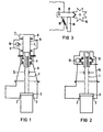
- a shut-off valve according to FIGS. 1 and 2 has a spindle 1, to which a valve plate 3 which can be placed on a seat 2 is molded.
- shut-off device 5 consisting of the spindle 1 with the valve plate 3 and the spindle nut 4 and a housing 6, forms a separate component.
- a likewise separate drive device 7 is placed on the shut-off device 5.
- This contains in a housing 8 a drive bushing 9 which can be coupled to the spindle nut 4.
- An electric motor not shown, is connected to the drive bushing 9 via a worm 10 and a worm wheel 11. The drive device 7 can be removed from the shut-off device 5.
- a spindle nut 12 designed as a worm wheel engages with the spindle 1.
- An electric motor not shown, is connected to the spindle nut 12 via a worm 13.
- the spindle 1 is driven without the interposition of a drive bushing.
- the drive device is integrated in the shut-off device. Both are inseparable from one housing 14.
- a brake for the spindle 1 consists of a gear wheel 15 connected to the spindle nut 12.
- a pawl 17, which engages between teeth of the gear wheel 15, is rotatable about a pin 16.
- a permanently installed block 18 prevents deflection of the pawl 17 in a certain direction of rotation and thus also a rotation of the gear 15 in a certain direction of rotation.
Landscapes
- Engineering & Computer Science (AREA)
- General Engineering & Computer Science (AREA)
- Mechanical Engineering (AREA)
- Mechanically-Actuated Valves (AREA)
- Braking Arrangements (AREA)
- Electrically Driven Valve-Operating Means (AREA)
- Control Of Combustion (AREA)
- Pens And Brushes (AREA)
Priority Applications (1)
| Application Number | Priority Date | Filing Date | Title |
|---|---|---|---|
| AT88110035T ATE96516T1 (de) | 1987-08-10 | 1988-06-23 | Absperrarmatur. |
Applications Claiming Priority (2)
| Application Number | Priority Date | Filing Date | Title |
|---|---|---|---|
| DE3726581 | 1987-08-10 | ||
| DE3726581 | 1987-08-10 |
Publications (3)
| Publication Number | Publication Date |
|---|---|
| EP0303801A1 EP0303801A1 (de) | 1989-02-22 |
| EP0303801B1 EP0303801B1 (de) | 1993-10-27 |
| EP0303801B2 true EP0303801B2 (de) | 1997-02-12 |
Family
ID=6333449
Family Applications (1)
| Application Number | Title | Priority Date | Filing Date |
|---|---|---|---|
| EP88110035A Expired - Lifetime EP0303801B2 (de) | 1987-08-10 | 1988-06-23 | Absperrarmatur |
Country Status (4)
| Country | Link |
|---|---|
| EP (1) | EP0303801B2 (es) |
| AT (1) | ATE96516T1 (es) |
| DE (1) | DE3885196D1 (es) |
| ES (1) | ES2043734T5 (es) |
Cited By (3)
| Publication number | Priority date | Publication date | Assignee | Title |
|---|---|---|---|---|
| US7615893B2 (en) | 2000-05-11 | 2009-11-10 | Cameron International Corporation | Electric control and supply system |
| US8106538B2 (en) | 2001-09-19 | 2012-01-31 | Cameron International Corporation | DC voltage converting device |
| US8212378B2 (en) | 2000-10-30 | 2012-07-03 | Cameron International Corporation | Control and supply system |
Families Citing this family (8)
| Publication number | Priority date | Publication date | Assignee | Title |
|---|---|---|---|---|
| DE19650947C2 (de) * | 1996-12-07 | 1999-11-04 | Hartmann & Braun Gmbh & Co Kg | Axialkupplung für einen Stellantrieb |
| DE20115473U1 (de) | 2001-09-19 | 2003-02-20 | Biester, Klaus, 29342 Wienhausen | Universelles Energieversorgungssystem |
| DE20018563U1 (de) * | 2000-10-30 | 2002-03-21 | CAMERON GmbH, 29227 Celle | Betätigungsvorrichtung, insbesondere für eine Drosseleinrichtung |
| DE20115471U1 (de) | 2001-09-19 | 2003-02-20 | Biester, Klaus, 29342 Wienhausen | Universelles Energieversorgungssystem |
| DE20115474U1 (de) | 2001-09-19 | 2003-02-20 | Biester, Klaus, 29342 Wienhausen | Gleichspannungs-Wandlervorrichtung |
| DE20115475U1 (de) | 2001-09-19 | 2003-02-20 | Biester, Klaus, 29342 Wienhausen | Gleichspannungs-Wandlervorrichtung |
| CN105240589B (zh) * | 2015-11-02 | 2018-09-04 | 新疆水利水电科学研究院 | 电动阀低功耗阀门的柱型控制装置 |
| CN107283278A (zh) * | 2017-07-29 | 2017-10-24 | 刘路清 | 一种用于钢板清洁去锈的自锁式磨料刷辊驱动装置 |
Family Cites Families (6)
| Publication number | Priority date | Publication date | Assignee | Title |
|---|---|---|---|---|
| BE553737A (es) * | 1955-03-25 | |||
| US2948839A (en) * | 1956-04-09 | 1960-08-09 | Conval Corp | Motor control for positioning device |
| CH383717A (de) * | 1959-05-02 | 1964-10-31 | Int Bremsengesellschaft Mbh | Verstellvorrichtung mit Umwandlung einer Drehbewegung in eine geradlinige Bewegung |
| DE1167431B (de) * | 1960-07-26 | 1964-04-09 | Fostoria Corp | Motorgetriebene Vorrichtung zur Betaetigung eines Ventilschaftes |
| DE1185031B (de) * | 1962-06-27 | 1965-01-07 | Zikesch Carl Herbert | Antrieb fuer Ventile, die in groesserer Anzahl in einer laengeren Hochdruckleitung untergebracht sind |
| DE2141519A1 (de) * | 1971-08-19 | 1973-02-22 | Kloeckner Humboldt Deutz Ag | Motorantrieb fuer steuerorgane |
-
1988
- 1988-06-23 EP EP88110035A patent/EP0303801B2/de not_active Expired - Lifetime
- 1988-06-23 DE DE88110035T patent/DE3885196D1/de not_active Expired - Fee Related
- 1988-06-23 ES ES88110035T patent/ES2043734T5/es not_active Expired - Lifetime
- 1988-06-23 AT AT88110035T patent/ATE96516T1/de not_active IP Right Cessation
Cited By (5)
| Publication number | Priority date | Publication date | Assignee | Title |
|---|---|---|---|---|
| US7615893B2 (en) | 2000-05-11 | 2009-11-10 | Cameron International Corporation | Electric control and supply system |
| US8212378B2 (en) | 2000-10-30 | 2012-07-03 | Cameron International Corporation | Control and supply system |
| US8536731B2 (en) | 2001-05-07 | 2013-09-17 | Cameron International Corporation | Electric control and supply system |
| US8106538B2 (en) | 2001-09-19 | 2012-01-31 | Cameron International Corporation | DC voltage converting device |
| US8212410B2 (en) | 2002-11-12 | 2012-07-03 | Cameron International Corporation | Electric control and supply system |
Also Published As
| Publication number | Publication date |
|---|---|
| ES2043734T5 (es) | 1997-04-01 |
| EP0303801A1 (de) | 1989-02-22 |
| ATE96516T1 (de) | 1993-11-15 |
| DE3885196D1 (de) | 1993-12-02 |
| ES2043734T3 (es) | 1994-01-01 |
| EP0303801B1 (de) | 1993-10-27 |
Similar Documents
| Publication | Publication Date | Title |
|---|---|---|
| EP1404956B1 (de) | Elektromotorischer antrieb mit einer schnecke | |
| EP0303801B2 (de) | Absperrarmatur | |
| EP0599083B1 (de) | Antriebseinheit zur Steuerung und Regelung von Armaturen od.dgl. | |
| DE3540652C2 (de) | Elektrischer Schraubendreher | |
| EP0410487B1 (de) | Notantrieb einer elektromotorisch antreibbaren Antriebseinheit | |
| EP1233690A1 (de) | Elektromotorischer stellantrieb | |
| DE60025230T2 (de) | Elektrisches bremsbetätigungsmodul für flugzeuge | |
| DE2629112C3 (de) | Schutzmechanismus zur verhinderung der uebertragung eines unzulaessigen drehmomentes, insbesondere ventil-schutzmechanismus fuer ventile | |
| DE2134027A1 (de) | Antriebsvorrichtung zum bewegen von fensterscheiben, schiebedaechern und dergleichen von kraftfahrzeugen | |
| DE3114708A1 (de) | Ventilantrieb | |
| EP3608557B1 (de) | Kugelgewindetrieb | |
| DE102008049251B4 (de) | Stellvorrichtung zur Umwandlung einer rotatorischen Bewegung in eine lineare Bewegung | |
| WO2020038952A1 (de) | Steer-by-wire-lenkgetriebe mit hohlwellenmotor und kugelgewindetrieb | |
| DE102004003665B4 (de) | Stellvorrichtung | |
| DE69102746T2 (de) | Elektromechanische Steuerung mit Hilfe einer Zentrifuge. | |
| DE10135141A1 (de) | Starter | |
| DE19519310A1 (de) | Differentialgetriebe für einen elektromotorisch betriebenen Bremsaktor | |
| DE29918221U1 (de) | Linearantrieb | |
| DE4447395A1 (de) | Stellantrieb | |
| DE2700928A1 (de) | Stellantrieb fuer luft- und drosselklappen, mischhaehne u.dgl. in heizungs- und lueftungsanlagen | |
| EP0305762A1 (de) | Elektromotorischer Stellantrieb mit zeitabhängiger Endlagen- Abschaltung zum Einsatz in Steuer- oder Regeleinrichtungen für strömende Medien | |
| DE3801904A1 (de) | Schraubgetriebe | |
| DE19803541B4 (de) | Stelleinrichtung zur automatisierten Betätigung eines rotatorisch und translatorisch bewegbaren Schaltelements eines Schaltgetriebes | |
| DE69504767T2 (de) | Schneckenvorrichtung zur Positionierung in Fahrzeugscheinwerfer | |
| DE102022004380B4 (de) | Anschlussadapter mit einer elektromechanischen Stellvorrichtung |
Legal Events
| Date | Code | Title | Description |
|---|---|---|---|
| PUAI | Public reference made under article 153(3) epc to a published international application that has entered the european phase |
Free format text: ORIGINAL CODE: 0009012 |
|
| AK | Designated contracting states |
Kind code of ref document: A1 Designated state(s): AT BE CH DE ES FR GB GR IT LI LU NL SE |
|
| 17P | Request for examination filed |
Effective date: 19890726 |
|
| 17Q | First examination report despatched |
Effective date: 19900508 |
|
| RIN1 | Information on inventor provided before grant (corrected) |
Inventor name: ZILL, HEINRICH Inventor name: HOLTFOTH, PETER |
|
| GRAA | (expected) grant |
Free format text: ORIGINAL CODE: 0009210 |
|
| AK | Designated contracting states |
Kind code of ref document: B1 Designated state(s): AT BE CH DE ES FR GB GR IT LI LU NL SE |
|
| PG25 | Lapsed in a contracting state [announced via postgrant information from national office to epo] |
Ref country code: IT Free format text: LAPSE BECAUSE OF FAILURE TO SUBMIT A TRANSLATION OF THE DESCRIPTION OR TO PAY THE FEE WITHIN THE PRE;WARNING: LAPSES OF ITALIAN PATENTS WITH EFFECTIVE DATE BEFORE 2007 MAY HAVE OCCURRED AT ANY TIME BEFORE 2007. THE CORRECT EFFECTIVE DATE MAY BE DIFFERENT FROM THE ONE RECORDED.SCRIBED TIME-LIMIT Effective date: 19931027 Ref country code: GR Free format text: LAPSE BECAUSE OF FAILURE TO SUBMIT A TRANSLATION OF THE DESCRIPTION OR TO PAY THE FEE WITHIN THE PRESCRIBED TIME-LIMIT Effective date: 19931027 Ref country code: SE Effective date: 19931027 |
|
| REF | Corresponds to: |
Ref document number: 96516 Country of ref document: AT Date of ref document: 19931115 Kind code of ref document: T |
|
| REF | Corresponds to: |
Ref document number: 3885196 Country of ref document: DE Date of ref document: 19931202 |
|
| REG | Reference to a national code |
Ref country code: ES Ref legal event code: FG2A Ref document number: 2043734 Country of ref document: ES Kind code of ref document: T3 |
|
| GBT | Gb: translation of ep patent filed (gb section 77(6)(a)/1977) |
Effective date: 19931125 |
|
| ET | Fr: translation filed | ||
| PG25 | Lapsed in a contracting state [announced via postgrant information from national office to epo] |
Ref country code: LU Free format text: LAPSE BECAUSE OF NON-PAYMENT OF DUE FEES Effective date: 19940630 |
|
| PLBI | Opposition filed |
Free format text: ORIGINAL CODE: 0009260 |
|
| 26 | Opposition filed |
Opponent name: MANNESMANN AG Effective date: 19940727 |
|
| NLR1 | Nl: opposition has been filed with the epo |
Opponent name: MANNESMANN AG |
|
| PLAW | Interlocutory decision in opposition |
Free format text: ORIGINAL CODE: EPIDOS IDOP |
|
| PLAW | Interlocutory decision in opposition |
Free format text: ORIGINAL CODE: EPIDOS IDOP |
|
| PUAH | Patent maintained in amended form |
Free format text: ORIGINAL CODE: 0009272 |
|
| STAA | Information on the status of an ep patent application or granted ep patent |
Free format text: STATUS: PATENT MAINTAINED AS AMENDED |
|
| 27A | Patent maintained in amended form |
Effective date: 19970212 |
|
| AK | Designated contracting states |
Kind code of ref document: B2 Designated state(s): AT BE CH DE ES FR GB GR IT LI LU NL SE |
|
| REG | Reference to a national code |
Ref country code: CH Ref legal event code: AEN Free format text: AUFRECHTERHALTUNG DES PATENTES IN GEAENDERTER FORM |
|
| NLR2 | Nl: decision of opposition | ||
| REG | Reference to a national code |
Ref country code: ES Ref legal event code: DC2A Kind code of ref document: T5 Effective date: 19970218 |
|
| ET3 | Fr: translation filed ** decision concerning opposition | ||
| NLR3 | Nl: receipt of modified translations in the netherlands language after an opposition procedure | ||
| GBTA | Gb: translation of amended ep patent filed (gb section 77(6)(b)/1977) | ||
| PGFP | Annual fee paid to national office [announced via postgrant information from national office to epo] |
Ref country code: AT Payment date: 19970602 Year of fee payment: 10 |
|
| PGFP | Annual fee paid to national office [announced via postgrant information from national office to epo] |
Ref country code: BE Payment date: 19970609 Year of fee payment: 10 |
|
| PGFP | Annual fee paid to national office [announced via postgrant information from national office to epo] |
Ref country code: ES Payment date: 19970611 Year of fee payment: 10 |
|
| PGFP | Annual fee paid to national office [announced via postgrant information from national office to epo] |
Ref country code: NL Payment date: 19970619 Year of fee payment: 10 |
|
| PG25 | Lapsed in a contracting state [announced via postgrant information from national office to epo] |
Ref country code: AT Free format text: LAPSE BECAUSE OF NON-PAYMENT OF DUE FEES Effective date: 19980623 |
|
| PG25 | Lapsed in a contracting state [announced via postgrant information from national office to epo] |
Ref country code: BE Free format text: LAPSE BECAUSE OF NON-PAYMENT OF DUE FEES Effective date: 19980630 |
|
| BERE | Be: lapsed |
Owner name: SIEMENS A.G. Effective date: 19980630 |
|
| PG25 | Lapsed in a contracting state [announced via postgrant information from national office to epo] |
Ref country code: NL Free format text: LAPSE BECAUSE OF NON-PAYMENT OF DUE FEES Effective date: 19990101 |
|
| NLV4 | Nl: lapsed or anulled due to non-payment of the annual fee |
Effective date: 19990101 |
|
| PGFP | Annual fee paid to national office [announced via postgrant information from national office to epo] |
Ref country code: GB Payment date: 19990616 Year of fee payment: 12 |
|
| PG25 | Lapsed in a contracting state [announced via postgrant information from national office to epo] |
Ref country code: ES Free format text: LAPSE BECAUSE OF NON-PAYMENT OF DUE FEES Effective date: 19990624 |
|
| PGFP | Annual fee paid to national office [announced via postgrant information from national office to epo] |
Ref country code: FR Payment date: 19990629 Year of fee payment: 12 |
|
| PGFP | Annual fee paid to national office [announced via postgrant information from national office to epo] |
Ref country code: DE Payment date: 19990820 Year of fee payment: 12 |
|
| PGFP | Annual fee paid to national office [announced via postgrant information from national office to epo] |
Ref country code: CH Payment date: 19990920 Year of fee payment: 12 |
|
| PG25 | Lapsed in a contracting state [announced via postgrant information from national office to epo] |
Ref country code: GB Free format text: LAPSE BECAUSE OF NON-PAYMENT OF DUE FEES Effective date: 20000623 |
|
| PG25 | Lapsed in a contracting state [announced via postgrant information from national office to epo] |
Ref country code: LI Free format text: LAPSE BECAUSE OF NON-PAYMENT OF DUE FEES Effective date: 20000630 Ref country code: CH Free format text: LAPSE BECAUSE OF NON-PAYMENT OF DUE FEES Effective date: 20000630 |
|
| GBPC | Gb: european patent ceased through non-payment of renewal fee |
Effective date: 20000623 |
|
| REG | Reference to a national code |
Ref country code: CH Ref legal event code: PL |
|
| PG25 | Lapsed in a contracting state [announced via postgrant information from national office to epo] |
Ref country code: FR Free format text: LAPSE BECAUSE OF NON-PAYMENT OF DUE FEES Effective date: 20010228 |
|
| REG | Reference to a national code |
Ref country code: FR Ref legal event code: ST |
|
| PG25 | Lapsed in a contracting state [announced via postgrant information from national office to epo] |
Ref country code: DE Free format text: LAPSE BECAUSE OF NON-PAYMENT OF DUE FEES Effective date: 20010403 |
|
| REG | Reference to a national code |
Ref country code: ES Ref legal event code: FD2A Effective date: 20010503 |