EP0303829A1 - Dispositif avertisseur pour roue à bandage pneumatique de véhicule - Google Patents
Dispositif avertisseur pour roue à bandage pneumatique de véhicule Download PDFInfo
- Publication number
- EP0303829A1 EP0303829A1 EP88111278A EP88111278A EP0303829A1 EP 0303829 A1 EP0303829 A1 EP 0303829A1 EP 88111278 A EP88111278 A EP 88111278A EP 88111278 A EP88111278 A EP 88111278A EP 0303829 A1 EP0303829 A1 EP 0303829A1
- Authority
- EP
- European Patent Office
- Prior art keywords
- tire
- rim
- sensing element
- actuating
- measuring device
- Prior art date
- Legal status (The legal status is an assumption and is not a legal conclusion. Google has not performed a legal analysis and makes no representation as to the accuracy of the status listed.)
- Granted
Links
- 230000000149 penetrating effect Effects 0.000 claims abstract 2
- 230000005540 biological transmission Effects 0.000 claims description 9
- 238000011156 evaluation Methods 0.000 claims description 3
- 239000000523 sample Substances 0.000 claims 2
- 238000005259 measurement Methods 0.000 description 2
- 230000035515 penetration Effects 0.000 description 2
- 239000007787 solid Substances 0.000 description 2
- 238000013459 approach Methods 0.000 description 1
- 238000013461 design Methods 0.000 description 1
- 238000011161 development Methods 0.000 description 1
- 230000018109 developmental process Effects 0.000 description 1
- 238000012806 monitoring device Methods 0.000 description 1
- 238000012544 monitoring process Methods 0.000 description 1
- 238000007493 shaping process Methods 0.000 description 1
- 238000012546 transfer Methods 0.000 description 1
- 238000013519 translation Methods 0.000 description 1
Images
Classifications
-
- B—PERFORMING OPERATIONS; TRANSPORTING
- B60—VEHICLES IN GENERAL
- B60C—VEHICLE TYRES; TYRE INFLATION; TYRE CHANGING; CONNECTING VALVES TO INFLATABLE ELASTIC BODIES IN GENERAL; DEVICES OR ARRANGEMENTS RELATED TO TYRES
- B60C23/00—Devices for measuring, signalling, controlling, or distributing tyre pressure or temperature, specially adapted for mounting on vehicles; Arrangement of tyre inflating devices on vehicles, e.g. of pumps or of tanks; Tyre cooling arrangements
- B60C23/06—Signalling devices actuated by deformation of the tyre, e.g. tyre mounted deformation sensors or indirect determination of tyre deformation based on wheel speed, wheel-centre to ground distance or inclination of wheel axle
Definitions
- the invention relates to a warning device according to the preamble of patent claim 1.
- the invention is therefore based on the object of improving a device of the type mentioned in such a way that not only a drop in tire pressure, but also the depressurized condition of the tire can be measured or displayed while driving.
- the invention has the advantage that it is not necessary to adapt the device to tire-specific air pressures of different makes or special operating states.
- the invention also has the advantage that a flattening of the tread of the tire as a result of a load when the tire pressure is not adequate is recognized by the evaluation device.
- Another advantage of the invention results from the simple and less prone to failure structure of the device.
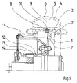
- Fig. 1 shows a vehicle wheel with a wheel bowl (1) and a rim (2)
- the rim base (3) is designed as a circumferential support surface for the tire (4) in the flattened state.
- the tire (4) is depressurized or almost depressurized, the inner surface (5) of the tread (6) of the tire (4) in contact with the roadway is supported on the rim base (3).
- the tire and rim system shown has an emergency running property, such that the part of the tire supported on the rim base (3) can continue to run as a "solid rubber tire”.
- a measuring device (7) which penetrates the rim well (3) or the rim (2) in the vicinity of the rim well (3) and into the interior (9 ) of the tire (4) protruding sensing element (8) in the form of a plunger (8).
- the end (10) of the plunger (8) protruding into the interior (9) is directed against the inner surface (5).
- the tappet (8) is in contact with the inner surface (5) approaching the rim base (3), or the inner surface (5) supported on the rim base (3), from a predetermined starting position in its longitudinal direction radially with respect to the rim base (3) against the wheel a restoring force adjustable.
- an adjustment path is generated as the output signal of the measuring device (7), which corresponds to the adjustment of the plunger (8).
- the travel path is via a with the Transfer the tappet (8), which is operatively connected, to a transmission device (12) rotating around the vehicle wheel.
- the actuating device (12) has an actuator (13) which can be adjusted by the output signal of the measuring device (7) via the transmission mechanism (11).
- the measuring device (7) with a translation device with which the generated travel can be changed in the sense of expanding the measuring range.
- the position of the actuator (13) is sensed by a sensor (14) which is arranged in an axially fixed manner and passed on to an evaluation and display device in the sense of DE-PS 28 13 058 mentioned at the beginning.
- the actuating device (12) and the measuring device (7) are arranged with respect to one another on the vehicle wheel such that the actuator (13) passes through the scanning range of the sensor (14) when the plunger (8) can be actuated by flattening the tire (4).
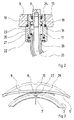
- Fig. 2 shows an embodiment of the measuring device (7), the housing (17) by a screw connection (15) and a seal (16) is connected to the rim base (3).
- the position of the tappet (8) relative to the rim base (3) is predetermined by a stop (18) of the housing (17) and by a support surface (19) of the tappet (8).
- the stop (18) can also be made adjustable, so that the position of the plunger (8) relative to Rim bed (3) is changeable. For example, by increasing the depth of penetration of the plunger (8) into the interior (9), the measurement can begin before the tire (4) is drastically flattened.
- a spring (21) is arranged in a chamber (20) of the housing (17), which is supported on the one hand on a support surface (22) which is stationary with respect to the housing (17) and on the other hand on an end face (23) of the plunger (8). As a result, the plunger (8) is biased against the stop (18) in its unactuated position.
- the chamber (20) is sealed off from the interior (9) of the tire (4) by a seal (24).
- the transmission mechanism (11) is formed by a flexible linkage (25) connected to the tappet (8) and an envelope (26) of the flexible linkage (25).
- the transmission mechanism (11) can be fastened with conventional fastening means, e.g. Clamps to be attached to the wheel bowl (1).
- conventional fastening means e.g. Clamps
- said cavity or this recess could serve to counteract an imbalance of the vehicle wheel caused by the measuring device (7) by means of a corresponding arrangement and design.
- Fig. 3 shows the measuring device (7) with an actuating auxiliary device (27) in the form of a leaf spring (27) which is firmly connected to the rim base (3) on one side.
- the free end (28) of the Leaf spring (27) is arranged between the plunger (8) and the inner surface (5), such that the plunger (8) can be actuated when the free end (28) is acted upon by the inner surface (5).
- the measuring range can then be varied by adjusting the plunger (8) and shaping the leaf spring (27) accordingly.
- the measuring device (7) can also be designed in the manner of a compressible chamber, which can be actuated by the inner surface (5) of the tire (4) approaching the rim base (3), a change in the chamber pressure affecting the adjustment mechanism ( 11) acting output signal can be generated.
- the measuring device (7) can also be used as a sensor, e.g. in the manner of a plunger coil or a proximity circuit, which can be excited by an approach of the inner surface (5) of the tire (4) to the rim base (3), an electrical output signal which can be generated thereby being used to adjust the adjustment mechanism.
Landscapes
- Engineering & Computer Science (AREA)
- Mechanical Engineering (AREA)
- Measuring Fluid Pressure (AREA)
Applications Claiming Priority (2)
| Application Number | Priority Date | Filing Date | Title |
|---|---|---|---|
| DE19873727875 DE3727875A1 (de) | 1987-08-21 | 1987-08-21 | Warneinrichtung fuer ein luftbereiftes rad eines fahrzeugs |
| DE3727875 | 1987-08-21 |
Publications (2)
| Publication Number | Publication Date |
|---|---|
| EP0303829A1 true EP0303829A1 (fr) | 1989-02-22 |
| EP0303829B1 EP0303829B1 (fr) | 1991-09-11 |
Family
ID=6334169
Family Applications (1)
| Application Number | Title | Priority Date | Filing Date |
|---|---|---|---|
| EP88111278A Expired - Lifetime EP0303829B1 (fr) | 1987-08-21 | 1988-07-14 | Dispositif avertisseur pour roue à bandage pneumatique de véhicule |
Country Status (5)
| Country | Link |
|---|---|
| US (1) | US4887067A (fr) |
| EP (1) | EP0303829B1 (fr) |
| JP (1) | JP2764585B2 (fr) |
| DE (2) | DE3727875A1 (fr) |
| ES (1) | ES2023984B3 (fr) |
Cited By (1)
| Publication number | Priority date | Publication date | Assignee | Title |
|---|---|---|---|---|
| CN112009670A (zh) * | 2020-09-03 | 2020-12-01 | 闫巍 | 一种航天客机滑行轮过度磨损提示机构 |
Families Citing this family (4)
| Publication number | Priority date | Publication date | Assignee | Title |
|---|---|---|---|---|
| DE19728601C2 (de) * | 1997-07-04 | 2003-10-30 | Bayerische Motoren Werke Ag | Fahrzeugrad mit einem Luftreifen und einem Notlaufring |
| US20040140888A1 (en) * | 2002-11-12 | 2004-07-22 | Simpson William A. | Low air pressure warning system for tires |
| US7421902B2 (en) | 2006-10-13 | 2008-09-09 | Smartire Systems, Inc. | Fluid pressure sensing method and apparatus |
| DE102006055878B4 (de) * | 2006-11-23 | 2020-12-03 | Huf Baolong Electronics Bretten Gmbh | Verfahren zum Zuordnen von Identifikationscodes in Funksignalen von Reifendruckkontrolleinrichtungen an Fahrzeugrädern zu deren Position und zum Durchführen des Verfahrens ausgestattetes Fahrzeug |
Citations (4)
| Publication number | Priority date | Publication date | Assignee | Title |
|---|---|---|---|---|
| DE447195C (de) * | 1926-01-27 | 1927-07-19 | Hermann Jacoby | Vorrichtung zum Anzeigen von Luftmangel in Druckluftreifen an Kraftwagen, Motorraedern o. dgl. |
| US3588813A (en) * | 1967-08-17 | 1971-06-28 | Kennard E Robinson | Tire pressure signal system |
| DE2813058C2 (de) * | 1978-03-25 | 1984-04-19 | Wabco Westinghouse Fahrzeugbremsen GmbH, 3000 Hannover | Reifendrucküberwachungseinrichtung |
| DE3503805A1 (de) * | 1985-02-05 | 1986-08-07 | Continental Gummi-Werke Ag, 3000 Hannover | Verfahren und vorrichtung zur messung der eindrueckung an einem reifen |
Family Cites Families (11)
| Publication number | Priority date | Publication date | Assignee | Title |
|---|---|---|---|---|
| DE820545C (de) * | 1950-03-16 | 1952-03-06 | Hans Gerl | Reifenluft-Kontrollgeraet bei Luftreifen fuer Lastkraftwagen und deren Anhaenger |
| US2925799A (en) * | 1957-07-30 | 1960-02-23 | Caldwell William Addison | Universal relief valve and pressure signal for pneumatic tires |
| DE1680495A1 (de) * | 1967-04-04 | 1971-09-30 | Glacomo Spaggiari | Anzeige-Vorrichtung fuer die Druckminderung bei Fahrzeugreifen,insbesondere Kraftfahrzeugreifen |
| US3680523A (en) * | 1970-10-28 | 1972-08-01 | Thomas Gaskins | Pressure indicator |
| SE7506969L (sv) * | 1974-06-25 | 1975-12-29 | Dunlop Ltd | Anordning for varning om punktering eller tomning av pneumatiska deck |
| US4117452A (en) * | 1977-04-06 | 1978-09-26 | Gould Inc. | Tire condition sensing apparatus |
| US4235184A (en) * | 1979-03-23 | 1980-11-25 | Sharon Steel Corporation | Strapping, seal and counterweight device for mounting tire pressure warning system sensors on tire rims |
| JPH0113428Y2 (fr) * | 1980-09-11 | 1989-04-19 | ||
| JPS5815323B2 (ja) * | 1980-12-26 | 1983-03-25 | 住友ゴム工業株式会社 | チユ−ブレスタイヤの内圧低下警報装置 |
| US4531112A (en) * | 1982-06-17 | 1985-07-23 | Thomas Stephen E | Method and apparatus for transmitting from within a pneumatic wheel assembly |
| DE3523774A1 (de) * | 1985-07-03 | 1987-01-08 | Bosch Gmbh Robert | Drucksensor |
-
1987
- 1987-08-21 DE DE19873727875 patent/DE3727875A1/de not_active Withdrawn
-
1988
- 1988-07-14 DE DE8888111278T patent/DE3864775D1/de not_active Expired - Lifetime
- 1988-07-14 EP EP88111278A patent/EP0303829B1/fr not_active Expired - Lifetime
- 1988-07-14 ES ES88111278T patent/ES2023984B3/es not_active Expired - Lifetime
- 1988-08-03 JP JP63192916A patent/JP2764585B2/ja not_active Expired - Fee Related
- 1988-08-16 US US07/232,742 patent/US4887067A/en not_active Expired - Lifetime
Patent Citations (4)
| Publication number | Priority date | Publication date | Assignee | Title |
|---|---|---|---|---|
| DE447195C (de) * | 1926-01-27 | 1927-07-19 | Hermann Jacoby | Vorrichtung zum Anzeigen von Luftmangel in Druckluftreifen an Kraftwagen, Motorraedern o. dgl. |
| US3588813A (en) * | 1967-08-17 | 1971-06-28 | Kennard E Robinson | Tire pressure signal system |
| DE2813058C2 (de) * | 1978-03-25 | 1984-04-19 | Wabco Westinghouse Fahrzeugbremsen GmbH, 3000 Hannover | Reifendrucküberwachungseinrichtung |
| DE3503805A1 (de) * | 1985-02-05 | 1986-08-07 | Continental Gummi-Werke Ag, 3000 Hannover | Verfahren und vorrichtung zur messung der eindrueckung an einem reifen |
Cited By (1)
| Publication number | Priority date | Publication date | Assignee | Title |
|---|---|---|---|---|
| CN112009670A (zh) * | 2020-09-03 | 2020-12-01 | 闫巍 | 一种航天客机滑行轮过度磨损提示机构 |
Also Published As
| Publication number | Publication date |
|---|---|
| JPS6456213A (en) | 1989-03-03 |
| EP0303829B1 (fr) | 1991-09-11 |
| DE3864775D1 (de) | 1991-10-17 |
| JP2764585B2 (ja) | 1998-06-11 |
| DE3727875A1 (de) | 1989-03-02 |
| ES2023984B3 (es) | 1992-02-16 |
| US4887067A (en) | 1989-12-12 |
Similar Documents
| Publication | Publication Date | Title |
|---|---|---|
| DE10144360B4 (de) | Verfahren zum Zuordnen von Reifendruckmessvorrichtungen eines Kraftfahrzeugs zu Radpositionen und Vorrichtung zum Messen des Reifendrucks | |
| EP0783419B1 (fr) | Procede et dispositif pour determiner la force longitudinale d'un pneumatique et pneumatique correspondant | |
| EP0418495B1 (fr) | Installation de surveillance de la pression d'un pneumatique | |
| DE69808028T2 (de) | Luftfeder, enthaltend eine aktive Komponente und eine Radaufhängungsanordnung und Verfahren zu deren Benutzung | |
| EP0333708B1 (fr) | Detecteur de la pression de pneus de vehicules a moteur | |
| DE60216153T2 (de) | Reifenüberwachungsverfahren und -vorrichtung eines Kraftfahrzeugs | |
| DE60319598T2 (de) | Verfahren und system zur bestimmung des schräglaufwinkels eines reifens während des fahrens eines fahrzeugs | |
| DE60015339T2 (de) | Drucküberwachungssystem | |
| DE3853499T2 (de) | Kraftmessvorrichtung. | |
| DE69806566T2 (de) | Messaufnehmer für einen Luftreifen | |
| EP0284895B1 (fr) | Méthode pour le gonflement d'un pneumatique de véhicule sous une pression correcte avec un dispositif pour le contrôle de la pression de pneumatiques | |
| EP2035243A1 (fr) | Procédé de détection de l'état d'un pneu | |
| EP2834611B1 (fr) | Procédé et dispositif pour contrôler la pression de gonflage | |
| DE69831797T2 (de) | Sicherheitseinsatz, der ein Vibrationssignal in Querrichtung erzeugt, und Vorrichtung zum Detektieren des Aufliegens eines Reifens auf einem Einsatz | |
| DE102019104692A1 (de) | Verfahren und Einrichtung zum Bestimmen der Orientierung einer Reifen-angebrachten Vorrichtung | |
| WO1989005239A1 (fr) | Capteur de la pression des pneus de vehicules a moteur | |
| DE102006033951A1 (de) | Vorrichtung und Verfahren zur Bestimmung einer Radlast eines Reifens eines Kraftwagens | |
| DE10329700A1 (de) | Verfahren und Vorrichtung zur Ermittlung des Reifenfülldrucks und der Radlast eines Fahrzeugreifens | |
| DE69310137T2 (de) | Fahrzeugrad mit reifendrucksensor | |
| DE3150869A1 (de) | Reifendruckwarnvorrichtung | |
| DE69722978T2 (de) | Einrichtung zum Überwachen des Luftdruckes in den Luftreifen eines Fahrzeuges | |
| DE69617747T2 (de) | Druckanzeigeeinrichtungen | |
| DE3810763A1 (de) | Druckschalter zur ueberwachung eines reifenluftdrucks, insbesondere von kraftfahrzeug-reifen | |
| EP0303829B1 (fr) | Dispositif avertisseur pour roue à bandage pneumatique de véhicule | |
| DE19854176A1 (de) | Vorrichtung zur laufenden Kontrolle des Betriebszustands der Reifen von Kraftfahrzeugen |
Legal Events
| Date | Code | Title | Description |
|---|---|---|---|
| PUAI | Public reference made under article 153(3) epc to a published international application that has entered the european phase |
Free format text: ORIGINAL CODE: 0009012 |
|
| AK | Designated contracting states |
Kind code of ref document: A1 Designated state(s): DE ES FR GB IT SE |
|
| 17P | Request for examination filed |
Effective date: 19890117 |
|
| 17Q | First examination report despatched |
Effective date: 19900503 |
|
| GRAA | (expected) grant |
Free format text: ORIGINAL CODE: 0009210 |
|
| AK | Designated contracting states |
Kind code of ref document: B1 Designated state(s): DE ES FR GB IT SE |
|
| ITF | It: translation for a ep patent filed | ||
| REF | Corresponds to: |
Ref document number: 3864775 Country of ref document: DE Date of ref document: 19911017 |
|
| ET | Fr: translation filed | ||
| GBT | Gb: translation of ep patent filed (gb section 77(6)(a)/1977) | ||
| REG | Reference to a national code |
Ref country code: ES Ref legal event code: FG2A Ref document number: 2023984 Country of ref document: ES Kind code of ref document: B3 |
|
| PLBE | No opposition filed within time limit |
Free format text: ORIGINAL CODE: 0009261 |
|
| STAA | Information on the status of an ep patent application or granted ep patent |
Free format text: STATUS: NO OPPOSITION FILED WITHIN TIME LIMIT |
|
| 26N | No opposition filed | ||
| PGFP | Annual fee paid to national office [announced via postgrant information from national office to epo] |
Ref country code: ES Payment date: 19930422 Year of fee payment: 6 |
|
| PG25 | Lapsed in a contracting state [announced via postgrant information from national office to epo] |
Ref country code: ES Free format text: LAPSE BECAUSE OF EXPIRATION OF PROTECTION Effective date: 19940715 |
|
| EAL | Se: european patent in force in sweden |
Ref document number: 88111278.3 |
|
| REG | Reference to a national code |
Ref country code: ES Ref legal event code: FD2A Effective date: 19990601 |
|
| REG | Reference to a national code |
Ref country code: GB Ref legal event code: IF02 |
|
| PGFP | Annual fee paid to national office [announced via postgrant information from national office to epo] |
Ref country code: GB Payment date: 20020710 Year of fee payment: 15 Ref country code: FR Payment date: 20020710 Year of fee payment: 15 |
|
| PGFP | Annual fee paid to national office [announced via postgrant information from national office to epo] |
Ref country code: DE Payment date: 20020711 Year of fee payment: 15 |
|
| PGFP | Annual fee paid to national office [announced via postgrant information from national office to epo] |
Ref country code: SE Payment date: 20020712 Year of fee payment: 15 |
|
| PG25 | Lapsed in a contracting state [announced via postgrant information from national office to epo] |
Ref country code: GB Free format text: LAPSE BECAUSE OF NON-PAYMENT OF DUE FEES Effective date: 20030714 |
|
| PG25 | Lapsed in a contracting state [announced via postgrant information from national office to epo] |
Ref country code: SE Free format text: LAPSE BECAUSE OF NON-PAYMENT OF DUE FEES Effective date: 20030715 |
|
| PG25 | Lapsed in a contracting state [announced via postgrant information from national office to epo] |
Ref country code: DE Free format text: LAPSE BECAUSE OF NON-PAYMENT OF DUE FEES Effective date: 20040203 |
|
| EUG | Se: european patent has lapsed | ||
| GBPC | Gb: european patent ceased through non-payment of renewal fee |
Effective date: 20030714 |
|
| PG25 | Lapsed in a contracting state [announced via postgrant information from national office to epo] |
Ref country code: FR Free format text: LAPSE BECAUSE OF NON-PAYMENT OF DUE FEES Effective date: 20040331 |
|
| REG | Reference to a national code |
Ref country code: FR Ref legal event code: ST |
|
| PG25 | Lapsed in a contracting state [announced via postgrant information from national office to epo] |
Ref country code: IT Free format text: LAPSE BECAUSE OF NON-PAYMENT OF DUE FEES;WARNING: LAPSES OF ITALIAN PATENTS WITH EFFECTIVE DATE BEFORE 2007 MAY HAVE OCCURRED AT ANY TIME BEFORE 2007. THE CORRECT EFFECTIVE DATE MAY BE DIFFERENT FROM THE ONE RECORDED. Effective date: 20050714 |