EP0303838A2 - Dispositif pour le traitement de l'air comprimé pour systèmes à air comprimé - Google Patents
Dispositif pour le traitement de l'air comprimé pour systèmes à air comprimé Download PDFInfo
- Publication number
- EP0303838A2 EP0303838A2 EP19880111635 EP88111635A EP0303838A2 EP 0303838 A2 EP0303838 A2 EP 0303838A2 EP 19880111635 EP19880111635 EP 19880111635 EP 88111635 A EP88111635 A EP 88111635A EP 0303838 A2 EP0303838 A2 EP 0303838A2
- Authority
- EP
- European Patent Office
- Prior art keywords
- pressure
- air dryer
- air
- regeneration
- valve
- Prior art date
- Legal status (The legal status is an assumption and is not a legal conclusion. Google has not performed a legal analysis and makes no representation as to the accuracy of the status listed.)
- Withdrawn
Links
Images



Classifications
-
- B—PERFORMING OPERATIONS; TRANSPORTING
- B60—VEHICLES IN GENERAL
- B60T—VEHICLE BRAKE CONTROL SYSTEMS OR PARTS THEREOF; BRAKE CONTROL SYSTEMS OR PARTS THEREOF, IN GENERAL; ARRANGEMENT OF BRAKING ELEMENTS ON VEHICLES IN GENERAL; PORTABLE DEVICES FOR PREVENTING UNWANTED MOVEMENT OF VEHICLES; VEHICLE MODIFICATIONS TO FACILITATE COOLING OF BRAKES
- B60T17/00—Component parts, details, or accessories of power brake systems not covered by groups B60T8/00, B60T13/00 or B60T15/00, or presenting other characteristic features
- B60T17/002—Air treatment devices
- B60T17/004—Draining and drying devices
-
- B—PERFORMING OPERATIONS; TRANSPORTING
- B01—PHYSICAL OR CHEMICAL PROCESSES OR APPARATUS IN GENERAL
- B01D—SEPARATION
- B01D53/00—Separation of gases or vapours; Recovering vapours of volatile solvents from gases; Chemical or biological purification of waste gases, e.g. engine exhaust gases, smoke, fumes, flue gases, aerosols
- B01D53/26—Drying gases or vapours
- B01D53/261—Drying gases or vapours by adsorption
Definitions
- the invention relates to a compressed air treatment device for compressed air systems, in particular for compressed air brake systems of commercial vehicles, of the type specified in the preamble of claim 1.
- the idle phase of the compressor that delivers the compressed air is used to regenerate the drying agent present in the air container by removing moisture.
- the air dryer is switched via its control input in such a way that the inlet of the air dryer is connected to a ventilation outlet.
- the dried regeneration air stored in the regeneration air reservoir during normal operation of the air dryer thus flows through the air dryer in the opposite direction in order to escape to the outside at the venting outlet, and withdraws when it flows through the air dryer the drying agent moisture.
- the pneumatic control input for switching the air dryer is connected via a control line to the output of the pressure regulator, which leads the pneumatic input and output signals which characterize the switching state of the pressure regulator.
- the pressure regulator is connected to the outlet of the air dryer via a compressed air line and switches off at a pressure at the air dryer outlet of approximately 8 bar and switches on again at a pressure of approximately 7.2 bar.
- the pressure regulator output connected to the control line is ventilated.
- This switching air which forms the external signal, reaches the control input of the air dryer and switches it over to regeneration mode.
- the switching valve which is controlled as a function of the pressure in the regeneration air reservoir, is switched into the control line.
- the compressed air treatment device with the characterizing features of claim 1 has the advantage that the pressure regulator does not switch the switching air for switching the air dryer directly but indirectly.
- the switching air itself is drawn from the compressed air supply at the outlet of the air dryer.
- the pressure regulator only cancels the effect of the locking device as soon as it switches from its switch-on phase to its switch-off phase, in which the outlet of the pressure regulator connected to the locking device is ventilated.
- the locking device has a pneumatic, low-power control input so that the maximum permissible pressure difference is not exceeded in pressure regulators with the double-seat valve described at the beginning.
- the known pressure regulators can thus continue to be used in the compressed air treatment device according to the invention, the full switching range of the pressure regulator of 0.8 bar being used for the regeneration operation.
- the locking device itself prevents ventilation of the control input of the air dryer during normal or drying operation of the air dryer, since the switch-on pressure of the pressure regulator is still above the upper pressure limit for the switching valve for multiple switching of the air dryer. If the electrical device fails, the device automatically switches to idle and thus the air dryer to regeneration mode.
- the compressed air supply to the compressed air system has priority, so that when air is required in the compressed air system, it is suddenly switched to normal operation, ie drying operation of the air dryer.
- the locking device consists of a pressure switch and control logic.
- the switching valve is designed as a 3/2-way solenoid valve with spring return, and at least one pressure switch that detects the storage pressure is connected to the regeneration air reservoir. There are preferably two pressure switches.
- the switching threshold of one pressure switch is set to the upper and the switching shaft of the other pressure switch to the lower pressure limit.
- the control logic links the output signals of the pressure switches and generates the switching signal for the 3/2-way solenoid valve.
- the switching valve is designed as a pneumatic 3/2-way valve with switching hysteresis, which switches to ventilation of the control input of the air dryer when the upper pressure limit is exceeded and switches back to venting of the control input of the air dryer when the pressure falls below the lower pressure limit.
- the locking device consists of a simple pressure switch and a 3/2-way solenoid valve controlled by the pressure switch, which is switched on in the connecting line between the pneumatically controlled 3/2-way valve and the outlet of the air dryer and interrupts the connecting line as long as the pressure regulator is turned off is in its switch-on phase.
- a saving of components and short connecting lines between the individual valves results if, according to a further embodiment of the invention, the pressure regulator is integrated into the air dryer itself.
- the compressed air preparation device shown schematically in FIG. 1 serves to supply compressed air systems, here a compressed air brake system for commercial vehicles, with compressed air.
- the compressed air reservoir of the compressed air brake system not shown here, are connected via a four-circuit protection valve 10 known per se filled, to which two service brake circuits, a parking brake and trailer circuit and a secondary consumer circuit are connected.
- the compressed air treatment device has an air compressor 11 and an air dryer 12 with inlet 13, outlet 14, control input 15 and ventilation outlet 16.
- the air dryer 12, which is designed as a single-container air dryer, is of a known type, as described, for example, in DE-OS 35 04 884.
- the compressed air entering the inlet 13 and conveyed by the air compressor 11 flows through a container filled with a drying agent and exits via a check valve at the outlet 14 of the air dryer 14.
- a check valve at the outlet 14 of the air dryer 14.
- a regeneration air reservoir 18 which is connected to the connection 17 of the air dryer 12 via a compressed air line 19, is tensioned by the dried compressed air.
- the compressed air line 19 there is a check valve 20 with a flow direction pointing towards the regeneration air reservoir 18 and a throttle 21 parallel to the check valve 20.
- regenerate the air dryer 12 it can be switched via its control input 15 so that its inlet 13 is connected to the ventilation outlet 16.
- air from the regeneration air reservoir 18 can flow through the throttle 21 in the now opposite flow direction, the drying agent in the container of the air dryer 12 and escape into the atmosphere at the vent outlet 16.
- the dried regeneration air flowing through the drying agent extracts moisture from the drying agent, as a result of which the latter is regenerated.
- a pressure regulator 22 is connected to the outlet 14 of the air dryer 12 connected to the input of the four-circuit protection valve 10.
- This pressure regulator 22 is also of a known type, which is described, for example, in DE-OS 33 08 547.
- a longitudinal section of the pressure regulator 22 used here is shown in FIG. It has a two-part valve housing 23, consisting of a base body 24 and a housing cover 25, which are screwed together with a seal 26 with an intermediate layer.
- a control piston 33 is rigidly connected, on the front of which the return spring 28 is supported and the back of which is loaded by an adjusting spring 34 which is supported on a spring plate 36 connected to an adjusting screw 35 and whose pretension can be adjusted via the adjusting screw 35 .
- the diaphragm 26 held between the base body 24 and the housing cover 25 of the regulator housing 23 is clamped on the control piston 33.
- Return spring 28, adjusting spring 34 and the surfaces of the control piston 33 and valve member 27 acted upon by the pressure in the valve chamber 37 between the inlet 31 and the passage opening 30 are so matched that the pressure regulator 22 at a pressure at the outlet 14 of the air dryer 12 of FIG. 8 controlled via the inlet 31 bar opens and closes again from 7.2 bar.
- the valve member 27 lifts off the valve seat 29 and compressed air reaches the outlet 32 of the pressure regulator 22.
- a pressure switch 38 is connected to the output of the pressure regulator 22. This is designed so that it is in the switch-on phase of the pressure regulator 22 when the valve member 27 rests on the valve seat 29 and the outlet 32 is not vented is closed and opens in the switch-off phase of the pressure regulator 22, ie when the valve member 27 is lifted from the valve seat 29 and the outlet 32 is vented.
- the pressure switch 38 is electrically connected to a control logic 39, as is shown in the circuit diagram in a conventional design in FIG. 3.
- the control input 15 of the air dryer 12 is connected via a control line 40 to the outlet 14 of the air dryer 12.
- a control valve 41 which is designed here as a 3/2-way solenoid valve with spring return, is arranged in the control line 40.
- the switching valve 41 is controlled by the control logic 39.
- the switching valve 41 is designed so that the control input 15 of the air dryer 12 is connected to the outlet 14 of the air dryer 12 in its unexcited basic position and is vented in its excited switching position.
- Two pressure switches 42 and 43 with different switching thresholds are connected to the regeneration air reservoir 18. Both pressure switches 42 and 43 are designed as break contacts, the first pressure switch 42 opening when a lower pressure limit value in the regeneration air reservoir 18 is exceeded and the second pressure switch 43 opening in the regeneration air reservoir 18 when an upper pressure limit value is exceeded.
- the lower pressure limit is between 0.5 and 1 bar and the upper pressure limit is 0.5 bar lower than the switch-on pressure of the pressure regulator 22, which here is approximately 7.2 bar.
- the two pressure switches 42 and 43 are electrically connected to the control logic 39.
- the control logic 39 is now designed such that it energizes or switches off the excitation winding 44 of the switching valve 41 in a predetermined manner by linking the output signals of the pressure switches 38, 42 and 43.
- the link is designed so that when the pressure regulator 22 is switched on, the switching valve 41 is always energized, so that the Control input 15 is vented in normal or drying operation of the air dryer 12.
- Pressure switch 38 and control logic 39 form a locking device which energizes the switching valve 41 irrespective of the output signal of the two pressure switches 42, 43 connected to the regeneration air reservoir 18 and thus locks it in its switchover position as long as the pressure regulator 22 is switched on.
- the switching valve 41 is energized when the pressure in the regeneration air reservoir 18 drops below the lower pressure limit value and is switched off again as soon as the pressure in the regeneration air reservoir 18 exceeds the upper pressure limit value.
- the control input 15 of the air dryer 12 is thereby connected to the outlet 14 of the air dryer 12 and is thus aerated.
- the vent outlet 16 of the air dryer 12 is opened and the air dryer 12 is switched to its regeneration mode.
- a first relay 45 is connected to a DC voltage source U B via the pressure switch 38 connected to the pressure regulator 22, a second relay 46 via the first pressure switch 42 connected to the regeneration air reservoir 18 and a third relay 47 via the second pressure switch 43 connected to the regeneration air reservoir 18 .
- the switching contact 45a of the first relay 45 is in series with the excitation winding 44 of the switching valve 41 at the DC voltage source U B.
- the switching contact 47a of the third relay 47 and the switching contact 46a of the second relay 46 are connected in series and are on the one hand at the DC voltage source U B and on the other hand at the excitation winding 44 of the switching valve 41.
- the second switching relay 46 also has a second switching contact 46b for producing one Self-holding circuit for relay 46 on, which is connected on the one hand to the input of the relay winding of the relay 46 and on the other hand to the switching valve-side connection of the switching contact 46a. All relays 45 are designed so that the switch contacts 45a, 46a, 46b and 47a are open when the relay windings are de-energized and closed when the relay windings are energized.
- the mode of operation of the compressed air treatment device 12 in connection with the control logic 39 according to FIG. 3 is as follows: As long as the pressure at the outlet 14 of the air dryer 12 is less than 8 bar, the pressure regulator 22 is in its switch-on phase and the pressure switch 38 is not vented and is therefore closed. The relay 45 is energized and the relay contact 45a is closed. The switching valve 41 is energized and switches to its working position in which the control input 15 of the air dryer 12 is vented. The air dryer 12 operates in the drying mode, ie the compressed air conveyed by the air compressor 11 flows through the air dryer 12 from its inlet 13 to the outlet 14 and is thereby dried and reaches the four-circuit protection valve 10.
- the pressure regulator 22 switches to its switch-off phase, as a result of which the outlet of the pressure regulator 22 connected to the pressure switch 38 is aerated.
- the pressure switch 38 thus opens and the relay 45 drops out.
- the switching contact 45a opens and the switching valve 41 is switched off.
- the switching valve 41 returns to its basic position, in which it connects the outlet 14 of the air dryer 12 to its control input 15.
- the air dryer 12 is switched over to its regeneration mode. Dried air from the regeneration air reservoir 18 now flows through the air dryer 12 and extracts moisture from the drying agent.
- the pressure switch 43 closes and the relay 47 is energized, as a result of which the switch contact 47a closes. If the pressure in the regeneration air tank 18 continues to drop below the lower pressure limit value, the pressure switch 42 also closes and the relay 46 is energized.
- the switching contacts 46a and 46b close, whereby on the one hand the field winding 44 of the switching valve 41 is connected to the direct voltage U B via the closed switching contact 47a of the relay 47 and on the other hand the self-holding circuit of the relay 46 becomes effective.
- the switching valve 41 switches over and the control input 15 of the air dryer 12 is vented. The air dryer 12 is thus switched over to drying mode.
- the relay 46 remains energized. If the pressure in the regeneration air reservoir 18 exceeds the upper pressure limit, then The pressure switch 47 also opens, the relay 46 drops out and the switching contact 47a interrupts the energization of the switching valve 41.
- the switching valve 41 switches back to its basic position, the control input 15 of the air dryer 12 is vented from the outlet 14 and the air dryer 12 switches again in the regeneration mode. This cycle is repeated continuously, with very good regeneration of the drying agent in the air dryer 12 being achieved.
- the pressure switch 38 closes and by energizing the switching valve 41, the regeneration operation of the air dryer 12 is interrupted and the drying operation of the air dryer 12 is established .
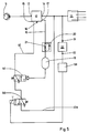
- FIG. 4 The embodiment of a compressed air treatment device shown in FIG. 4 largely corresponds to that in FIG. 1, so that the same components are provided with the same reference numerals.
- the pressure regulator 22 ' In contrast to the compressed air treatment device according to FIG. 1, here the pressure regulator 22 'is not connected to the outlet 14 of the air dryer 12 but switched on between the air compressor 11 and the inlet 13 of the air dryer 12.
- the pressure regulator 22 ' is approximately modified and detects the pressure at the outlet 14 of the air dryer via a connecting line 48'.
- the mode of operation of this compressed air treatment device is identical to that described in FIG. 1.
- the switching valve 141 is designed as a pneumatically controlled 3/2-way valve with spring return, the pneumatic one Control input is connected to the regeneration air reservoir 18.
- the switching valve 141 has a switching hysteresis, one switching threshold of which corresponds to the lower pressure limit value and the other switching threshold of which corresponds to the upper pressure limit value, so that the switching valve 141 switches at a pneumatic control pressure which exceeds the upper pressure limit value and the control line 40 between the outlet 14 and the Control input 15 of air dryer 12 closes and, at a control pressure which is less than the lower pressure limit value, switches back to its basic position by the return spring, in which control input 15 of air dryer 12 is vented.
- a 3/2-way solenoid valve 149 which is controlled by the pressure switch 138, is arranged in the line section 40a of the control line 40 connecting the outlet 14 of the air dryer 12 to the switching valve 141.
- the pressure switch 138 which in turn is connected to the output of the pressure regulator 22, forms, together with the 3/2-way solenoid valve 149, the locking device already mentioned in FIG. 1, which, just like there, the ventilation of the control input 15 of the air dryer 12 by the switching valve 141 independently of the pressure in Regeneration air reservoir 18 is blocked as long as the pressure regulator 22 is switched on and supplies a pneumatic single signal to the pressure regulator 38.
- the 3/2-way solenoid valve 149 is designed such that it vents the connection of the switching valve 141 in its de-energized basic position and connects it to the outlet 14 of the air dryer 12 in its energized working position.
- the pressure switch 138 is modified in such a way that it is open when the pressure regulator 22, that is to say unventilated output 32, is open and closes when the pressure regulator 22, that is to say vented output 32, is switched off.
- the switching valve 141 vents the control input 15 in its basic position and connects the control input 15 with the in its reversed working position Connection of the 3/2-way solenoid valve 149.
- the 3/2-way solenoid valve 149 assumes the basic position shown in FIG. Regardless of the switching position of the switching valve 141 due to the pressure level in the regeneration air reservoir 18, the control input 15 of the air dryer 12 is vented, so that the air dryer is in drying mode. If the output pressure of the air dryer 12 reaches the value of 8 bar, the pressure regulator 22 switches off and the pressure switch 138 is vented. This closes, so that the excitation winding of the 3/2-way solenoid valve 149 is energized. The latter switches to its working position and connects the connection of the switching valve 141 to the outlet 14 of the air dryer 12.
- the control input 15 of the air dryer 12 is now ventilated, so that the air dryer 12 switches over to its regeneration mode, or vented, so that the air dryer 12 switches back to the drying operation.
- the control input 15 is vented when the pressure in the regeneration air reservoir 18 exceeds the upper pressure limit value, and the control input 15 is vented as soon as the pressure in the regeneration air reservoir 18 falls below the lower pressure limit value.
- the upper pressure limit is again about 0.5 bar below the switch-on pressure of the pressure regulator 22, here 7.2 bar, while the lower pressure limit is again between 0.5 and 1 bar.
- the pressure regulator 22 is integrated into the air dryer 12 itself.
- Air dryer 12 and pressure control valve 22, which form a structural unit, are shown in Fig. 6 in the circuit detail.
- the container 50 containing the drying agent is arranged in series with a check valve 51 between the inlet 13 and the outlet 14 of the air dryer 12.
- the connection 17 for the compressed air line 19 to the regeneration air tank 18 is connected to the outlet of the tank 15 or to the inlet of the check valve 51.
- a pressure relief valve 52 is connected, the outlet of which is connected to the vent outlet 16 via a silencer 53.
- the pressure relief valve 52 has an additional pneumatic control input 54, which forms the control input 15 of the air dryer 12.
- the pressure regulator 22 consists of a pneumatically controllable 3/2-way valve 55 with adjustable spring return, one connection of which is connected to the outlet 14 of the air dryer 12 together with the pneumatic control input.
- the second connection of the 3/2-way valve 55 is connected to the pressure switch 38, while the third connection is vented.
- the input of the pressure switch 38 is vented.
- the 3/2-way valve 55 is reversed and the pressure switch 38 is vented. If the pressure at the outlet 14 of the air dryer 12 falls below the switch-on pressure of the pressure regulator 22 of 7.2 bar, the 3/2-way valve 55 is reset by the return spring and the pressure switch 38 is vented.
- the output of the pressure switch 38 is in turn fed to the control logic 39 which, in the manner already described, the switching valve 41 designed as a 3/2-way solenoid valve in the outlet 14 of the air dryer 12 controls with the control input 15 of the air dryer 12 connecting control line 40.
- the structure and mode of operation of the compressed air treatment device according to FIG. 6 correspond to that shown in FIG. 1, so that the same components are provided with the same reference symbols.
- the pressure valve 56 in the air dryer 12 which short-circuits the container 50 when the pressure at the inlet 13 of the air dryer 12 is exceeded during the drying operation and bypasses the container 50 and directs the compressed air directly to the outlet 14 of the air dryer 12.
- control logic 39 does not need to be implemented with electrical switching relays, but is expediently designed as electronic logic logic.
- the pressure switches 38, 42 and 43 can also be designed as closers, which close in the opposite manner as described above above the set pressure threshold and open below the set pressure threshold. This must be taken into account in the control logic 39, so that it supplies the switching signals for the switching valve 41 in the same way as described.
- a single pressure switch with switching hysteresis or a pressure sensor can be provided, which delivers an output signal proportional to the pressure in the regeneration air reservoir 18 to the control logic 39.
- the control logic 39 could contain a Schmitt trigger which, when its upper and lower switching thresholds are exceeded, delivers a switching signal with the opposite effect to the switching valve 41.
- the control logic 39 it is possible during the Switch-off phase of the pressure regulator 22 to bring about a multiple regeneration of the air dryer 12 in various ways.
- the switching cycle of the air dryer 12 from its regeneration phase to its drying phase can be set via a time relay or can be controlled by a moisture sensor that senses the moisture of the drying agent in the container of the air dryer 12. Repeated regeneration can also be achieved during the switch-off phase of the pressure regulator 22 by means of a counter which triggers the ventilation of the control input 15 of the air dryer 12 by the switching valve 41 when a predetermined counting cycle is reached.
Landscapes
- Engineering & Computer Science (AREA)
- Chemical & Material Sciences (AREA)
- Analytical Chemistry (AREA)
- General Chemical & Material Sciences (AREA)
- Oil, Petroleum & Natural Gas (AREA)
- Chemical Kinetics & Catalysis (AREA)
- Transportation (AREA)
- Mechanical Engineering (AREA)
- Drying Of Gases (AREA)
- Valves And Accessory Devices For Braking Systems (AREA)
Applications Claiming Priority (2)
| Application Number | Priority Date | Filing Date | Title |
|---|---|---|---|
| DE19873727603 DE3727603A1 (de) | 1987-08-19 | 1987-08-19 | Druckluftaufbereitungseinrichtung fuer druckluftsysteme |
| DE3727603 | 1987-08-19 |
Publications (2)
| Publication Number | Publication Date |
|---|---|
| EP0303838A2 true EP0303838A2 (fr) | 1989-02-22 |
| EP0303838A3 EP0303838A3 (fr) | 1989-07-26 |
Family
ID=6334032
Family Applications (1)
| Application Number | Title | Priority Date | Filing Date |
|---|---|---|---|
| EP88111635A Withdrawn EP0303838A3 (fr) | 1987-08-19 | 1988-07-20 | Dispositif pour le traitement de l'air comprimé pour systèmes à air comprimé |
Country Status (2)
| Country | Link |
|---|---|
| EP (1) | EP0303838A3 (fr) |
| DE (1) | DE3727603A1 (fr) |
Cited By (6)
| Publication number | Priority date | Publication date | Assignee | Title |
|---|---|---|---|---|
| WO1991016224A1 (fr) * | 1990-04-12 | 1991-10-31 | Allied-Signal Inc. | Systeme de commande de charge/purge pour secheur par air avec controle d'humidite |
| WO1991016225A1 (fr) * | 1990-04-12 | 1991-10-31 | Allied-Signal Inc. | Systeme de commande de charge/purge pour un dessicateur d'air a temps de charge limite |
| WO1995029832A1 (fr) * | 1994-04-28 | 1995-11-09 | Alliedsignal Truck Brake Systems Company | Valve de regulation de differentiel de pression pour systeme a air comprime |
| US6332917B1 (en) * | 1997-02-21 | 2001-12-25 | J. Lorch Gesellschaft & Co. Gmbh | Processing system for the preparation of compressed air |
| EP1504977A1 (fr) * | 2003-08-05 | 2005-02-09 | Haldex Brake Corporation | Système d'alimentation d'air comprimé |
| EP2492118B1 (fr) | 2011-02-25 | 2017-12-13 | WABCO GmbH | Procédé de fonctionnement d'une installation de traitement de l'air comprimé dans un véhicule, installation de traitement de l'air comprimé dotée d'un tel procédé, véhicule doté d'une telle installation de traitement de l'air comprimé et produit de programme informatique |
Families Citing this family (3)
| Publication number | Priority date | Publication date | Assignee | Title |
|---|---|---|---|---|
| DE4041710A1 (de) * | 1990-12-24 | 1992-06-25 | Wabco Westinghouse Fahrzeug | Druckluftanlage mit einem hochdruckteil und einem niederdruckteil |
| CN107685725B (zh) * | 2017-07-25 | 2019-12-03 | 湖北航天技术研究院特种车辆技术中心 | 一种混合动力底盘的供气系统 |
| EP4552936A1 (fr) | 2023-11-07 | 2025-05-14 | ZF CV Systems Global GmbH | Procédé de commande d'un dispositif d'alimentation en air comprimé et dispositif d'alimentation en air comprimé pour un système d'air comprimé d'un véhicule utilitaire |
Family Cites Families (5)
| Publication number | Priority date | Publication date | Assignee | Title |
|---|---|---|---|---|
| DE3139682A1 (de) * | 1981-10-06 | 1983-05-05 | Robert Bosch Gmbh, 7000 Stuttgart | Lufttrocknungseinrichtung fuer druckluftanlage |
| DE3139683C2 (de) * | 1981-10-06 | 1986-02-20 | Robert Bosch Gmbh, 7000 Stuttgart | Lufttrocknungsvorrichtung |
| DE3308547A1 (de) * | 1983-03-10 | 1984-09-13 | Robert Bosch Gmbh, 7000 Stuttgart | Druckluftversorgungseinrichtung fuer druckluftsysteme |
| US4549888A (en) * | 1984-11-07 | 1985-10-29 | Allied Corporation | Automatic control for an external air supply |
| DE3504884A1 (de) * | 1985-01-16 | 1986-07-17 | Robert Bosch Gmbh, 7000 Stuttgart | Druckluftaufbereitungsvorrichtung |
-
1987
- 1987-08-19 DE DE19873727603 patent/DE3727603A1/de not_active Withdrawn
-
1988
- 1988-07-20 EP EP88111635A patent/EP0303838A3/fr not_active Withdrawn
Cited By (8)
| Publication number | Priority date | Publication date | Assignee | Title |
|---|---|---|---|---|
| US5103576A (en) * | 1989-01-26 | 1992-04-14 | Allied Signal Inc. | Charge/purge control system for air dryer with humidity control |
| WO1991016224A1 (fr) * | 1990-04-12 | 1991-10-31 | Allied-Signal Inc. | Systeme de commande de charge/purge pour secheur par air avec controle d'humidite |
| WO1991016225A1 (fr) * | 1990-04-12 | 1991-10-31 | Allied-Signal Inc. | Systeme de commande de charge/purge pour un dessicateur d'air a temps de charge limite |
| WO1995029832A1 (fr) * | 1994-04-28 | 1995-11-09 | Alliedsignal Truck Brake Systems Company | Valve de regulation de differentiel de pression pour systeme a air comprime |
| US6332917B1 (en) * | 1997-02-21 | 2001-12-25 | J. Lorch Gesellschaft & Co. Gmbh | Processing system for the preparation of compressed air |
| EP1504977A1 (fr) * | 2003-08-05 | 2005-02-09 | Haldex Brake Corporation | Système d'alimentation d'air comprimé |
| JP2005052831A (ja) * | 2003-08-05 | 2005-03-03 | Haldex Brake Corp | 圧縮空気供給システム |
| EP2492118B1 (fr) | 2011-02-25 | 2017-12-13 | WABCO GmbH | Procédé de fonctionnement d'une installation de traitement de l'air comprimé dans un véhicule, installation de traitement de l'air comprimé dotée d'un tel procédé, véhicule doté d'une telle installation de traitement de l'air comprimé et produit de programme informatique |
Also Published As
| Publication number | Publication date |
|---|---|
| DE3727603A1 (de) | 1989-03-02 |
| EP0303838A3 (fr) | 1989-07-26 |
Similar Documents
| Publication | Publication Date | Title |
|---|---|---|
| DE69210614T2 (de) | Druckluftanlage mit zwei lufttrocknern | |
| EP2539196B1 (fr) | Dispositif de préparation de l'air comprimé pour véhicule | |
| EP0212101A2 (fr) | Procédé pour sécher de l'air comprimé | |
| EP1042151A1 (fr) | Installation electronique de traitement d'air comprime | |
| EP1957335A1 (fr) | Dispositif pour traiter de l'air comprime, et procede pour le faire fonctionner | |
| EP0831383B1 (fr) | Régulateur pour installations de production d'air comprimé dans des véhicules | |
| EP1508488B2 (fr) | Installation de production d'air comprimé pour véhicule et méthode pour le faire fonctionner | |
| EP0303838A2 (fr) | Dispositif pour le traitement de l'air comprimé pour systèmes à air comprimé | |
| DE69216721T3 (de) | Gas Dryer | |
| DE19700243C1 (de) | Druckluftaufbereitungseinrichtung für Kraftfahrzeug-Druckluftanlagen | |
| DE2421915C3 (de) | Relaisventil für eine blockiergeschützte Fahrzeug-Druckluftbremsanlage | |
| DE69200955T2 (de) | Bremsdruckregeleinrichtung. | |
| DE3216395C2 (de) | Lufttrockner, insbesondere für Druckluftbremsanlagen von Kraftfahrzeugen | |
| EP0289712A2 (fr) | Régulateur de pression | |
| DE2633161C3 (de) | Zweileitungs-Bremsanlage für Kraftfahrzeuge mit Anhänger | |
| EP1386811A1 (fr) | Installation d'alimentation en air comprimé pour des installations d'air comprimé de véhicules | |
| EP0169303B1 (fr) | Valve de commande pour remorques | |
| EP0114192B1 (fr) | Soupape de commande de remorque | |
| EP2789512B2 (fr) | Dispositif de préparation d'air comprimé pour un véhicule utilitaire | |
| DE102012102490C5 (de) | Druckluftaufbereitungseinrichtung für ein Nutzfahrzeug | |
| EP0060545B1 (fr) | Dispositif anti-bloqueur | |
| DE2419244C2 (de) | Blockierschutzeinrichtung für Bremsanlagen von Fahrzeugen | |
| DE2402375C2 (de) | Blockierschutzvorrichtung für druckluftgebremste Kraftfahrzeuge | |
| AT234533B (de) | Druckregler mit Reifenfüllanschluß | |
| DE3308547A1 (de) | Druckluftversorgungseinrichtung fuer druckluftsysteme |
Legal Events
| Date | Code | Title | Description |
|---|---|---|---|
| PUAI | Public reference made under article 153(3) epc to a published international application that has entered the european phase |
Free format text: ORIGINAL CODE: 0009012 |
|
| AK | Designated contracting states |
Kind code of ref document: A2 Designated state(s): DE FR GB IT SE |
|
| PUAL | Search report despatched |
Free format text: ORIGINAL CODE: 0009013 |
|
| AK | Designated contracting states |
Kind code of ref document: A3 Designated state(s): DE FR GB IT SE |
|
| 17P | Request for examination filed |
Effective date: 19891214 |
|
| 17Q | First examination report despatched |
Effective date: 19910311 |
|
| RAP3 | Party data changed (applicant data changed or rights of an application transferred) |
Owner name: ROBERT BOSCH GMBH |
|
| STAA | Information on the status of an ep patent application or granted ep patent |
Free format text: STATUS: THE APPLICATION IS DEEMED TO BE WITHDRAWN |
|
| 18D | Application deemed to be withdrawn |
Effective date: 19930202 |