EP0303905A2 - Raccord à brides - Google Patents
Raccord à brides Download PDFInfo
- Publication number
- EP0303905A2 EP0303905A2 EP88112692A EP88112692A EP0303905A2 EP 0303905 A2 EP0303905 A2 EP 0303905A2 EP 88112692 A EP88112692 A EP 88112692A EP 88112692 A EP88112692 A EP 88112692A EP 0303905 A2 EP0303905 A2 EP 0303905A2
- Authority
- EP
- European Patent Office
- Prior art keywords
- ring
- flange
- flange connection
- waveguide
- connection according
- Prior art date
- Legal status (The legal status is an assumption and is not a legal conclusion. Google has not performed a legal analysis and makes no representation as to the accuracy of the status listed.)
- Granted
Links
Images

Classifications
-
- H—ELECTRICITY
- H01—ELECTRIC ELEMENTS
- H01P—WAVEGUIDES; RESONATORS, LINES, OR OTHER DEVICES OF THE WAVEGUIDE TYPE
- H01P1/00—Auxiliary devices
- H01P1/04—Fixed joints
- H01P1/042—Hollow waveguide joints
Definitions
- the invention relates to a flange connection for round waveguides.
- the generation and conduction of high-power microwaves is of great importance, since electromagnetic radiation can be used to heat the plasma.
- Frequencies in the range from a few GHz to a few hundred GHz are preferably used.
- the oversized waveguides required have cross dimensions of a few dozen to a few centimeters. They are often circular in cross-section.
- a waveguide Basically, it is the task of a waveguide to guide the electromagnetic waves from the place of their generation to the place of their use and, if possible, without changing the type and intensity of the waves. How well a waveguide can do its job essentially depends on how constant its cross section is. Abrupt changes of the same, as occur preferably in the frontal connection of waveguides, lead, for example, to the mode converter sion and are particularly disruptive. It is therefore important that the waveguides have the smallest possible manufacturing tolerances (eg with regard to their cross-sectional shape) and are connected coaxially with great accuracy.
- a flange connection is known from ISO standard, publication 154-4, "Flanges for wave guides", for coupling round waveguides. Flanges are attached to the ends of the waveguides, e.g. by soldering, which are pressed together by two interlocking, interlocking toothed rings that are screwed together, screwed together.
- the object of the invention is therefore to provide a flange connection for round waveguides, which achieves the coaxiality of two adjoining waveguides with great accuracy, is simple to assemble and inexpensive to manufacture.
- the solution is that the coaxiality of two round, adjoining waveguides with a radially resilient centering ring encloses one end of each of the two waveguides.
- the flange connection is designed such that it can be fitted in the manner of a bayonet lock.
- a particularly preferred embodiment of the flange connection allows it to be assembled and temporarily fixed without the aid of tools.
- a flange connection which comprises at least one independent flange ring which is rotatably but non-displaceably attached to the waveguide in the axial direction.
- Fig. 1 shows a section through a flange connection according to the invention.
- the starting point are two waveguides 1a, 1b, which are to be coaxially coupled.
- These are round waveguides made of a metal, such as phosphorized copper (material DIN 1787), with an outside diameter of about 120 mm and a wall thickness of about 3 mm.
- the waveguide An essential requirement for the waveguide is that its roundness and its wall thickness have small manufacturing tolerances. If necessary, the waveguides must be brought to a uniform wall thickness at their ends. What cannot normally be avoided, however, is the fact that waveguides to be joined together have different outer radii at their ends due to the manufacturing inaccuracy. In this case in particular, the invention provides the best possible remedy, provided the two waveguides meet the above-mentioned requirements with regard to roundness and wall thickness.
- the waveguides 1a, 1b each have a circumferential groove 5a, 5b near their ends, in each of which a snap ring 6a, 6b is seated.
- the snap rings 6a, 6b protrude from the grooves 5a, 5b and can e.g. be made from a bronze wire.
- the essence of the invention is now to use a centering ring 3, which surrounds the two waveguides 1a, 1b at one of their ends.
- the centering ring 3 is designed so that it has a spring effect in the radial direction. If the waveguides 1a, 1b differ at their ends with regard to their outer radii, the centering ring 3 automatically brings them into a coaxial position.
- a flange connection is used to couple the two waveguides 1a, 1b rigidly. According to a preferred embodiment of the invention, it looks as follows:
- Two flange rings 2a, 2b are placed over the waveguides 1a, 1b, the inside diameters of which are just large enough that the flange rings 2a, 2b can be easily moved against the waveguides 1a, 1b, but that they cannot slide over the snap rings 6a, 6b .
- the flange rings 2a, 2b can consist, for example, of material DIN 1725 (AlMgSi alloy) and are preferably surface-treated so that they are better on the waveguides 1a, 1b slide. In practice, it has proven effective to ematalize the flange rings (electrolytic treatment in a titanium oxalate bath). This surface treatment leads to advantageously compact surfaces and is made, for example, by Contraves AG in Zurich.
- the flange rings 2a, 2b each have a circumferential recess 7a, on a side facing the end of the waveguide. 7b, which is large enough to hold the snap ring 6a or. 6b to be able to record.
- a plurality of radially displaceable ring holders 10a, 10b, distributed over the circumference of the flange ring, are arranged on the flange rings 2a, 2b. In Fig. 1 only one ring holder is shown for each flange ring.
- the closed end 15 is underlaid with an elastic ring 12 and a washer 13.
- the elastic ring 12 ensures that the coupling screw 4 still has some free play when it is screwed as far as possible in the direction of the waveguide 1a.
- the coupling screw 4 is provided with a thread.
- the flange ring 2b has a threaded bush 14 at this point.
- a bayonet bore 11 in the flange ring 2a opposite the threaded bush 14 corresponds to a preferred embodiment of the invention and enables a simple construction of the flange connection.
- Fig. 2 shows an axial section through a centering ring according to the invention.
- the centering ring is made, for example, of metal, preferably of ematalized material DIN 1725, and has an inner diameter which is slightly smaller than the outer diameter of the waveguide to be coupled, so that it can encompass the latter without play.
- a radial spring effect is there achieved by that the centering ring is provided with incisions 9 which run parallel to the axis of the centering ring.
- the incisions 9 penetrate alternately from below and from above to a given depth.
- the incisions 9 are arranged at an azimulatal distance of 15 °.
- the centering rings have top and bottom centering ring flanges 8a, 8b. Furthermore, the incisions 9 coming from above penetrate to the lower centering ring flanges 8b and those coming from below to the upper centering ring flanges 8a.
- the centering ring flanges 8b increase the resistance to deformation below the incisions 9 of the centering ring coming from above. Mutatis mutandis can be said for the centering flange 8a.
- the width of the centering ring has to be determined in such a way that on the one hand the waveguides are enclosed over a sufficiently large width to obtain the effect according to the invention, on the other hand that the flange connection takes up as little space as possible.
- the width of the centering ring is approximately 15 mm.
- the width of the centering ring, the dimension of the centering ring flanges and the number and type of cuts must be adapted to the respective requirements.
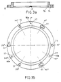
- FIG. 3a shows a flange ring according to the invention in axial section and FIG. 3b shows a top view of the latter.
- 3a and 3b the threaded bush 14, the bayonet bore 11 and the circumferential recess 7a can be seen again.
- 3b shows in particular how the threaded bushings 14 and the bayonet bores 11 can be arranged.
- three threaded bushings 14 and three bayonet bores 11 are alternately arranged at an azimuthal distance of 60 °.
- a captive coupling screw 4 as described above.
- the advantage of installing threaded bushings 14 and bayonet bores 11 on a flange ring in the manner described above is that the flange connection can be constructed with two identical flange rings 2a, 2b. This makes the manufacture and construction of the flange connection easier.
- the flange ring is equipped with guide grooves 17 for the ring holder 10.
- a bore 18a is also provided in each groove, so that the ring holder 10 can be fastened with a screw.
- Fig. 4 shows a section through a ring holder.
- An oval bore 18b is provided for fastening the ring holder with a screw 20 on the flange ring.
- the screw 20 is underlaid with a spring ring 19, which ensures that the ring holder is held in its respective position.
- the ring holder is preferably L-shaped so that it can be easily pushed back and forth without tools. Likewise, it has a recess 7c at one end facing the waveguide, which recess can accommodate the part of a snap ring protruding from the groove of the waveguide when the ring holder is advanced (cf. FIG. 1).
- a round waveguide 1a which has a circumferential groove 5a at a suitable distance from one end, meets the desired requirements in terms of manufacturing accuracy both in terms of roundness and in terms of wall thickness.
- a flange ring 2a with captive coupling screws 4 and ring holders 10a as shown, for example, in FIG. 3b, is placed over the end of the waveguide 1a. Then a snap ring 6a is inserted into the groove 5a of the waveguide. The flange ring 2a is advanced to the snap ring 6a and by advancing the ring holder 10a, which causes the flange ring 6a to slide back against a center of the waveguide 1a prevent being fixed in this position. Of course, it is still axially rotatable about the waveguide 1a.
- the coupling screws 4 are screwed in until the elastic ring 12 is clamped between the closed end 15 and the washer 13. Because of the elastic ring 12, the coupling screw 4 is not rigid on the flange ring, but can be moved somewhat. In this way, manufacturing inaccuracies of bayonet bores 11 of an opposite flange ring can be accommodated.
- a centering ring 3 is placed half over the end of a waveguide 1a. If the spacing of the groove 5a is selected appropriately, the centering ring 3 can be pushed over the waveguide 1a until it contacts the flange ring 2a and then just about half the width surrounds the waveguide 1a.
- the centering ring 3 clamps on the waveguide 1a. Note that both hands are now free to take the second waveguide 1b, slide it into the centering ring 3 and rotate it in the desired direction (think of the case that the waveguide 1b is curved), the bayonet catch close and tighten the coupling screws 4 by hand until the flange connection is provisionally fixed. Now you have both hands free to e.g. finally tighten the coupling screws 4 with a wrench.
- a flange connection according to the invention can be at least provisionally constructed with two hands, ie by one person, without tools. It is particularly clever, for example, to design a ring holder or a coupling screw lock so that it do not offer a point of attack for tools such as screwdrivers or wrenches, so that these parts cannot be removed by mistake.
- each waveguide is compatible with several, different coupling arrangements (third-party systems, vacuum seals, etc.).
- connection according to the invention connects round waveguides coaxially and that it is extremely simple to set up.
Landscapes
- Waveguide Connection Structure (AREA)
- Mutual Connection Of Rods And Tubes (AREA)
Applications Claiming Priority (2)
| Application Number | Priority Date | Filing Date | Title |
|---|---|---|---|
| DE19873727797 DE3727797A1 (de) | 1987-08-20 | 1987-08-20 | Flanschverbindung |
| DE3727797 | 1987-08-20 |
Publications (3)
| Publication Number | Publication Date |
|---|---|
| EP0303905A2 true EP0303905A2 (fr) | 1989-02-22 |
| EP0303905A3 EP0303905A3 (en) | 1990-04-25 |
| EP0303905B1 EP0303905B1 (fr) | 1993-10-20 |
Family
ID=6334136
Family Applications (1)
| Application Number | Title | Priority Date | Filing Date |
|---|---|---|---|
| EP88112692A Expired - Lifetime EP0303905B1 (fr) | 1987-08-20 | 1988-08-04 | Raccord à brides |
Country Status (4)
| Country | Link |
|---|---|
| US (1) | US4878037A (fr) |
| EP (1) | EP0303905B1 (fr) |
| JP (1) | JPS6461101A (fr) |
| DE (2) | DE3727797A1 (fr) |
Families Citing this family (5)
| Publication number | Priority date | Publication date | Assignee | Title |
|---|---|---|---|---|
| US5434585A (en) * | 1992-11-20 | 1995-07-18 | Gardiner Communications, Inc. | Microwave antenna having a ground isolated feedhorn |
| GB2292481B (en) * | 1994-08-17 | 1998-10-21 | Continental Microwave Technolo | Microwave radio antenna assembly |
| EP2093413B1 (fr) * | 2008-02-19 | 2011-01-12 | Continental Automotive GmbH | Dispositif de couplage |
| EP2093412B1 (fr) * | 2008-02-19 | 2011-01-19 | Continental Automotive GmbH | Dispositif de couplage |
| EP2208883B1 (fr) * | 2009-01-19 | 2015-07-22 | Continental Automotive GmbH | Dispositif de couplage |
Family Cites Families (12)
| Publication number | Priority date | Publication date | Assignee | Title |
|---|---|---|---|---|
| US1295263A (en) * | 1918-09-18 | 1919-02-25 | Norsk Hydro Elektrisk | Flange connection. |
| US2783295A (en) * | 1952-01-18 | 1957-02-26 | Gen Electric | Waveguide seal |
| US2892987A (en) * | 1955-02-18 | 1959-06-30 | Metal Fabricators Corp | Waveguide assembly |
| GB843229A (en) * | 1958-02-24 | 1960-08-04 | Scottish Agricultural Ind Ltd | Improvements in tube couplers |
| US3034808A (en) * | 1958-10-09 | 1962-05-15 | Consolidation Coal Co | Flexible pipe coupling |
| DE1441678B2 (de) * | 1964-12-29 | 1971-03-11 | Feiten & Guilleaume Carlswerk AG, 5000KoIn | Anordnung zur zentrierung der enden stumpf aneinanderstossendermetallischer hohlleiter |
| US3414297A (en) * | 1965-04-09 | 1968-12-03 | Raphael T Pollia | Pipe coupling containing a detachable flange |
| DE2030338B2 (de) * | 1970-06-19 | 1972-11-09 | Siemens AG, 1000 Berlin u. 8000 München | Anordnung zur gasdruckdichten verbindung von hohlleitern zur uebertragung elektromagnetischer wellen |
| US3778799A (en) * | 1972-03-28 | 1973-12-11 | Cables De Lyon Geoffroy Delore | Safety device for pipe lines under gas pressure |
| FR2351509A1 (fr) * | 1976-05-12 | 1977-12-09 | Cables De Lyon Geoffroy Delore | Procede et dispositif de raccordement simplifie de deux guides d'ondes circulaires |
| DE3130680A1 (de) * | 1981-08-03 | 1983-02-17 | Heraeus Quarzschmelze Gmbh, 6450 Hanau | "rohrfoermiger koerper mit flansch" |
| US4962991A (en) * | 1985-01-23 | 1990-10-16 | Raytheon Company | Quick-disconnect waveguide connector assembly |
-
1987
- 1987-08-20 DE DE19873727797 patent/DE3727797A1/de not_active Withdrawn
-
1988
- 1988-07-06 JP JP63168643A patent/JPS6461101A/ja active Pending
- 1988-08-04 DE DE88112692T patent/DE3885038D1/de not_active Expired - Fee Related
- 1988-08-04 EP EP88112692A patent/EP0303905B1/fr not_active Expired - Lifetime
- 1988-08-19 US US07/233,826 patent/US4878037A/en not_active Expired - Fee Related
Also Published As
| Publication number | Publication date |
|---|---|
| DE3727797A1 (de) | 1989-03-02 |
| EP0303905B1 (fr) | 1993-10-20 |
| DE3885038D1 (de) | 1993-11-25 |
| EP0303905A3 (en) | 1990-04-25 |
| JPS6461101A (en) | 1989-03-08 |
| US4878037A (en) | 1989-10-31 |
Similar Documents
| Publication | Publication Date | Title |
|---|---|---|
| DE10216003A1 (de) | Dockingvorrichtung | |
| EP0628734B1 (fr) | Dispositif de fixation pour relier de manière amovible un tube polygonal, en particulier un tube à profil rectangulaire | |
| EP0303905B1 (fr) | Raccord à brides | |
| DE69620475T2 (de) | Käfigmutter mit federwirkung | |
| DE3244516A1 (de) | Vorrichtung zur loesbaren verbindung des geraetetraegers mit der schiene einer leuchte, z. b. fuer leuchtstofflampen | |
| DE68906240T2 (de) | Vorrichtung zum durchtrennen von pfaehlen. | |
| DE3442231A1 (de) | Raumkonstruktion | |
| DE8712088U1 (de) | Elektro-Kochplatte | |
| DE832165C (de) | Elektrische Hohlrohr-Wellenfuehrung | |
| DE4326442A1 (de) | Abstandshalter zur Fixierung einer Leiterplatte in einem Gehäuse und elektrisches Gerät mit einer Leiterplatte und einem Abstandshalter | |
| DE9420034U1 (de) | Seilkreuzklemme | |
| DE3602159C2 (fr) | ||
| EP0438630A1 (fr) | Douille de lampe anti-déflagrante | |
| DE1028639B (de) | Einseitig kurzgeschlossener Hohlleiter-abschnitt, der mit einer Vorrichtung zum Anschluss einer Koaxialleitung versehen ist | |
| DE1541578C3 (de) | Mikrowellen-Impedanztransformator | |
| DD235769A1 (de) | Halterung fuer elektrische geraete in gerasteter einschubtechnik | |
| EP0849478A1 (fr) | Bande d'emballage pour éléments de fixation | |
| DE102016120378A1 (de) | Tragstrukturelement, Tragstruktur und Möbel | |
| DE202021102897U1 (de) | Rohrverbinder zur Herstellung einer lösbaren Verbindung zwischen mindestens zwei Rohren und Möbelstück mit einem solchen Rohrverbinder | |
| DE1154843B (de) | Loesbare Kupplung fuer Rundhohlleiter der Mikrowellentechnik | |
| DE2153414C3 (de) | Honwerkzeug | |
| DE2309804C3 (de) | Klemmvorrichtung | |
| AT407284B (de) | Klemmvorrichtung für teleskopierbare bauteile | |
| DE1230631B (de) | Vorrichtung zum Verbinden zweier Anschlussteile mittels einer UEberwurfmutter | |
| DE1572978C3 (de) | Wahlweise mit einer Achse eines Geräts fest oder auskuppelbar zu ver bindender Drehknopf |
Legal Events
| Date | Code | Title | Description |
|---|---|---|---|
| PUAI | Public reference made under article 153(3) epc to a published international application that has entered the european phase |
Free format text: ORIGINAL CODE: 0009012 |
|
| AK | Designated contracting states |
Kind code of ref document: A2 Designated state(s): CH DE FR GB IT LI NL |
|
| PUAL | Search report despatched |
Free format text: ORIGINAL CODE: 0009013 |
|
| AK | Designated contracting states |
Kind code of ref document: A3 Designated state(s): CH DE FR GB IT LI NL |
|
| 17P | Request for examination filed |
Effective date: 19901012 |
|
| 17Q | First examination report despatched |
Effective date: 19921211 |
|
| GRAA | (expected) grant |
Free format text: ORIGINAL CODE: 0009210 |
|
| AK | Designated contracting states |
Kind code of ref document: B1 Designated state(s): CH DE FR GB IT LI NL |
|
| PG25 | Lapsed in a contracting state [announced via postgrant information from national office to epo] |
Ref country code: IT Free format text: LAPSE BECAUSE OF FAILURE TO SUBMIT A TRANSLATION OF THE DESCRIPTION OR TO PAY THE FEE WITHIN THE PRE;WARNING: LAPSES OF ITALIAN PATENTS WITH EFFECTIVE DATE BEFORE 2007 MAY HAVE OCCURRED AT ANY TIME BEFORE 2007. THE CORRECT EFFECTIVE DATE MAY BE DIFFERENT FROM THE ONE RECORDED.SCRIBED TIME-LIMIT Effective date: 19931020 Ref country code: NL Effective date: 19931020 Ref country code: FR Effective date: 19931020 Ref country code: GB Effective date: 19931020 |
|
| REF | Corresponds to: |
Ref document number: 3885038 Country of ref document: DE Date of ref document: 19931125 |
|
| EN | Fr: translation not filed | ||
| NLV1 | Nl: lapsed or annulled due to failure to fulfill the requirements of art. 29p and 29m of the patents act | ||
| GBV | Gb: ep patent (uk) treated as always having been void in accordance with gb section 77(7)/1977 [no translation filed] |
Effective date: 19931020 |
|
| PLBE | No opposition filed within time limit |
Free format text: ORIGINAL CODE: 0009261 |
|
| STAA | Information on the status of an ep patent application or granted ep patent |
Free format text: STATUS: NO OPPOSITION FILED WITHIN TIME LIMIT |
|
| PG25 | Lapsed in a contracting state [announced via postgrant information from national office to epo] |
Ref country code: CH Effective date: 19940831 Ref country code: LI Effective date: 19940831 |
|
| 26N | No opposition filed | ||
| REG | Reference to a national code |
Ref country code: CH Ref legal event code: PL |
|
| PG25 | Lapsed in a contracting state [announced via postgrant information from national office to epo] |
Ref country code: DE Effective date: 19950503 |