EP0303937A2 - Filter mit Tiefenwirkung - Google Patents
Filter mit Tiefenwirkung Download PDFInfo
- Publication number
- EP0303937A2 EP0303937A2 EP88112895A EP88112895A EP0303937A2 EP 0303937 A2 EP0303937 A2 EP 0303937A2 EP 88112895 A EP88112895 A EP 88112895A EP 88112895 A EP88112895 A EP 88112895A EP 0303937 A2 EP0303937 A2 EP 0303937A2
- Authority
- EP
- European Patent Office
- Prior art keywords
- filter
- filter body
- filter elements
- density
- conduit
- Prior art date
- Legal status (The legal status is an assumption and is not a legal conclusion. Google has not performed a legal analysis and makes no representation as to the accuracy of the status listed.)
- Granted
Links
Images
Classifications
-
- B—PERFORMING OPERATIONS; TRANSPORTING
- B01—PHYSICAL OR CHEMICAL PROCESSES OR APPARATUS IN GENERAL
- B01D—SEPARATION
- B01D29/00—Filters with filtering elements stationary during filtration, e.g. pressure or suction filters, not covered by groups B01D24/00 - B01D27/00; Filtering elements therefor
- B01D29/11—Filters with filtering elements stationary during filtration, e.g. pressure or suction filters, not covered by groups B01D24/00 - B01D27/00; Filtering elements therefor with bag, cage, hose, tube, sleeve or like filtering elements
- B01D29/13—Supported filter elements
- B01D29/15—Supported filter elements arranged for inward flow filtration
-
- B—PERFORMING OPERATIONS; TRANSPORTING
- B01—PHYSICAL OR CHEMICAL PROCESSES OR APPARATUS IN GENERAL
- B01D—SEPARATION
- B01D29/00—Filters with filtering elements stationary during filtration, e.g. pressure or suction filters, not covered by groups B01D24/00 - B01D27/00; Filtering elements therefor
- B01D29/11—Filters with filtering elements stationary during filtration, e.g. pressure or suction filters, not covered by groups B01D24/00 - B01D27/00; Filtering elements therefor with bag, cage, hose, tube, sleeve or like filtering elements
- B01D29/111—Making filtering elements
-
- B—PERFORMING OPERATIONS; TRANSPORTING
- B01—PHYSICAL OR CHEMICAL PROCESSES OR APPARATUS IN GENERAL
- B01D—SEPARATION
- B01D2201/00—Details relating to filtering apparatus
- B01D2201/18—Filters characterised by the openings or pores
- B01D2201/182—Filters characterised by the openings or pores for depth filtration
-
- B—PERFORMING OPERATIONS; TRANSPORTING
- B01—PHYSICAL OR CHEMICAL PROCESSES OR APPARATUS IN GENERAL
- B01D—SEPARATION
- B01D2201/00—Details relating to filtering apparatus
- B01D2201/60—Shape of non-cylindrical filtering elements
Definitions
- This invention relates to a filter of depth layer type which can remove impurities from a fluid with very high reliability in spite of a simple structure.
- a filter body of a filter of depth layer type has such a density distribution that the density is lowest in an area of its inlet side where a fluid such as oil to be filtered flows into the filter, and the density is progressively increased toward an area of its outlet side where the oil flows out from the filter.
- the filter of depth layer type can arrest a large amount of large and small impurities at a low pressure with least possibility of clogging.
- a filter of so-called roll paper type is known as an example of prior art filters of this kind.
- a filtering material is wound into the form of a roll, and one of the axial ends of the roll is radially most compressed to have a highest density so as to provide a density distribution in which the density progressively decreases from that end toward the other end of the roll.
- a fluid such as oil is supplied from the large-diameter side toward the small-diameter side of the roll, that is, from the low-density inlet side toward the high-density outlet side of the roll to remove impurities from the oil.
- a filter of herringbone twill type for filtering a fluid such as oil is also known as another example of prior art filters of this kind.
- the filter of twill type includes a filter body made by winding a braid-like filtering material in a twill pattern around a hollow cylindrical core member. The manner of winding is such that the filtering material is initially closely wound under a strong tension on the outer peripheral surfare of the core member and is then progressively coarsely wound under a progressively lower tension. That is, the filter body of the filter of twill type has a density distribution in which the density becomes progressively higher radially inward.
- the filter of roll paper type described above, creases tend to be produced on the surface of the filter body during compression of the filtering material in the radial direction, and, when these surface creases are produced as a result of strong compression, undesirable paths of oil are formed in the filter body through which oil flows directly without being filtered. Therefore, the filter of roll paper type has had the problem that the desired delicate density distribution cannot be provided in the filter body due to the impossibility of strong compression of the filtering material, and the impurity arresting capability cannot be improved.
- the total length of the filtering material wound in the twill pattern around the core member is large, and, in addition, the filtering material must be wound while changing the tension and direction of winding to provide the radial density distribution described above.
- the filter of twill type has had the problem that the requirement of a great deal of labor and time results in a high cost, and uniformity of the properties of products is difficult to attain.
- a filter of depth layer type comprising a generally cylindrical filter body formed by laminating a plurality of filter elements each in the form of a thin sheet of a filtering material having a central hole, the holes providing a continuous conduit extending in the axial direction through the filter body when the filter elements are laminated, the filter body having a density distribution in which the density is lowest at the outer peripheral are a serving as an inlet for a fluid to be filtered and becomes progressively higher toward the conduit serving as an outlet for the fluid to be filtered.
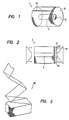
- Fig. 1 shows an embodiment of the filter of depth layer type according to the present invention.
- the filter includes a filter body 2 which is cylindrical in shape and formed by lamination many filter elements 6.
- the filter elements 6 are each in the form of a disc having a central hole 10, and a pair of holding plates 8 are mounted on both ends respectively of the laminate consisting of the filter elements 6. when the filter elements 6 are laminated, their central holes 10 are continuously aligned to define a through-hole 4 or conduit extending through the center of the filter body 2 as shown in Fig. 1.
- Each of the holding plates 8 is in the form of a frusto-conical disc having an opening 12 at the top of the frustum, and these holding plates 8 are mounted in such a relation that the tops of the frusto-conical discs confront each other.
- the holding plates 8 are retained in position by a pressure of fixtures 14 to inpart a holding presswer to the laminated filter elements 6.
- the value of this holding pressure is merely such that the holding plates 8 engage at least at their outer peripheral edges with the outermost filter elements 6.
- a fluid such as oil to be filtered flows into the filter body 2 from the outer peripheral surface of the filter body 2 and flows out from the central conduit 4 of the filter body 2.
- the frusto-conical holding plates 8 are mounted on both ends respectively of the filter body 2 as described already, the radially inner portions of the filter elements 6 are more strongly compressed then the radially outer portions and have a density higher than that of the latter. That is, the density distribution in the laminated filter elements 6 conforms to the frusto-conical shape of the holding plates 8. Therefore, relatively large impurities contained in the oil are arrested in the radially outer portion of the filter body 2, and relatively small impurities are arrested in the radially inner filter-body portion where the density of the filter elements 6 is high.
- the filter of depth layer type of the present invention exhibits a high capability of arresting impurities with least possibility of clogging.
- the filter elements 6 employed in the aforementioned embodiment are circular in shape. However, as shown in Fig.3, an elongate web of filtering material may be successively folded to provide a laminate 30 of filter elements.
- the laminate 30 formed in this manner has a shape similar to a prism.
- Such a laminate 30 may be directly used as a filter body, or its cornets may be cut away to provide a cylindrical filter body as described with reference to Figs. 1 and 2.
- the holding plates 8 having a frusto-conical shape are employed by way of example.
- the holding plates 8 in the present invention are in no way limited to such a specific shape, and those having a pyramidal shape or a stepwise inclining shape may also be employed.
- the taper of the holding plates 8 and the degree of pressurization by the holding plates 8 may be suitably changed as required.
- the holding plates 8 having the frusto-conical shabe need not be provided on both sider, and one of them may be replaced by a flat plate.
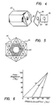
- the filter includes a filter body 42 which is in the form of a hexagonal prism in its overall shape and has a central through-hole or conduit 44.
- This filter body 42 is formed by alternately laminating many filter elements 46 in three different directions, that is, at an angle of 120° therebetween to constitute the shape of the hexagonal prism.
- Each of the filter elements 46 is in the form of a rectangular sheet of a filtering material such as paper or nonwoven cloth and has a central circular hole 48.
- the ratio between the short and long sides of the rectangular sheet is preferably 1: ⁇ 3.
- These filter elements 46 are laminated so as to form a hexagonal external shape as described above and so that their circular holes 48 are continuously aligned to define the conduit 44 extending through the center of the filter body 42.
- this filter body 42 has the function of depth layer filtration in that the filter density is low in its outer peripheral portion and progressively increases toward the center of the filter body 42.
- This filter body 42 may be suitably compressed in the direction of lamination.
- the filter body 42 When the filter body 42 is thus compressed in the direction of lamination, the superposed states of the portions of the filter elements 46 in the areas A, B and C are changed to change the distances between the portions of the filter elements 46 in the individual areas.
- the filter 42 body a has a total length L1 before pressurization, and this total length L1 is reduced to a length L2 after pressurization.
- the degree of pressurization is expressed as and the relation between the degree of pressurization and the degree of compression is as shown in Fig. 6. It will be seen in Fig.
- the filter element portions in the area C are compressed in proportion to the degree of pressurization of all the filter elements 46 as shown by a curve t C .
- the filter element portions in the areas B start to be compressed after the degree of pressurization of all the filter elements 46 exceeds about 30% as shown by a curve t B
- the filter element portions in the areas A start to be compressed after the degree of pressurization of all the filter elements 46 exceeds about 60% as shown by a curve t A .
- the states of compression of the portions of the filter elements 46 in the areas A, B and C can be suitably changed.
- holding plates are disposed at both ends respectively of the filter body 42, and, after the step of predetermined pressurization as described above, the holding plates are fixed in position by suitable fixing means.
- the aforementioned second embodiment has referred to employment of filter body in the form of a hexagonal prism.
- the present invention is it no way limited to a filter body of such a specific shape, and the shape and directions of lamination of the filter elements 46 may be suitably modified to provide filter bodies of any other shapes including an octagonal prism.
Landscapes
- Chemical & Material Sciences (AREA)
- Chemical Kinetics & Catalysis (AREA)
- Filtering Materials (AREA)
- Lubrication Details And Ventilation Of Internal Combustion Engines (AREA)
- Filtration Of Liquid (AREA)
Applications Claiming Priority (4)
| Application Number | Priority Date | Filing Date | Title |
|---|---|---|---|
| JP206540/87 | 1987-08-21 | ||
| JP62206539A JPS6451109A (en) | 1987-08-21 | 1987-08-21 | Deep bed filtration type filter |
| JP62206540A JPS6451110A (en) | 1987-08-21 | 1987-08-21 | Deep bed filtration type filter |
| JP206539/87 | 1987-08-21 |
Publications (3)
| Publication Number | Publication Date |
|---|---|
| EP0303937A2 true EP0303937A2 (de) | 1989-02-22 |
| EP0303937A3 EP0303937A3 (en) | 1989-06-14 |
| EP0303937B1 EP0303937B1 (de) | 1992-11-11 |
Family
ID=26515704
Family Applications (1)
| Application Number | Title | Priority Date | Filing Date |
|---|---|---|---|
| EP88112895A Expired - Lifetime EP0303937B1 (de) | 1987-08-21 | 1988-08-08 | Filter mit Tiefenwirkung |
Country Status (6)
| Country | Link |
|---|---|
| US (1) | US4968425A (de) |
| EP (1) | EP0303937B1 (de) |
| KR (1) | KR920003762B1 (de) |
| CN (1) | CN1011480B (de) |
| DE (1) | DE3875860T2 (de) |
| RU (1) | RU1793943C (de) |
Cited By (1)
| Publication number | Priority date | Publication date | Assignee | Title |
|---|---|---|---|---|
| WO2004050211A1 (en) * | 2002-12-03 | 2004-06-17 | Sungshin Engineering Co.,Ltd | Deep bed filter cartridge |
Families Citing this family (7)
| Publication number | Priority date | Publication date | Assignee | Title |
|---|---|---|---|---|
| US5340541A (en) * | 1993-03-05 | 1994-08-23 | Eli Lilly And Company | Automated Karl Fischer titration apparatus and method |
| US6391265B1 (en) * | 1996-08-26 | 2002-05-21 | Biosite Diagnostics, Inc. | Devices incorporating filters for filtering fluid samples |
| US6099608A (en) * | 1998-07-30 | 2000-08-08 | 3M Innovative Properties Company | Rotating filtration cartridge and blower for HVAC applications |
| US8220640B2 (en) * | 2007-07-23 | 2012-07-17 | Cummins Filtration Ip, Inc. | Stack-disk filter cartridge |
| USD615164S1 (en) * | 2009-06-29 | 2010-05-04 | Protective Industries, Inc. | Open ended industrial pipe cap |
| CN105641995A (zh) * | 2014-11-12 | 2016-06-08 | 宜兴市天马环保工程有限公司 | 一种新型精密过滤器 |
| CN114917661A (zh) * | 2021-01-31 | 2022-08-19 | 湖南迪易清环保科技有限公司 | 一种台型滤芯及水处理装置 |
Family Cites Families (17)
| Publication number | Priority date | Publication date | Assignee | Title |
|---|---|---|---|---|
| DE145055C (de) * | 1900-01-01 | |||
| US2201628A (en) * | 1938-11-16 | 1940-05-21 | Du Pont | Renewable type filter |
| GB555609A (en) * | 1942-02-26 | 1943-08-31 | Cecil Gordon Vokes | Improvements relating to filters provided with cleaning means |
| BE454202A (de) * | 1943-12-30 | |||
| US2697524A (en) * | 1950-06-22 | 1954-12-21 | William A Foust | Liquid filter cartridge |
| US2604994A (en) * | 1950-10-17 | 1952-07-29 | Wm W Nugent & Co Inc | Fiber disk filter assembly |
| CH306629A (de) * | 1951-10-04 | 1955-04-30 | Gmbh Robert Bosch | Zellenfilter. |
| US2753047A (en) * | 1953-01-27 | 1956-07-03 | A R Wood Mfg Company | Filter |
| US2816663A (en) * | 1954-08-09 | 1957-12-17 | Purolator Products Inc | Disc type filter |
| DE1110614B (de) * | 1954-11-13 | 1961-07-13 | Faudi Feinbau G M B H | Auswechselbares Filterelement |
| US2863561A (en) * | 1955-01-20 | 1958-12-09 | Screen Products Inc | Stacked disk filter |
| DE1109648B (de) * | 1957-06-25 | 1961-06-29 | Fram Corp | Filterelement zum Einsatz in ein zylindrisches, starres Filtergehaeuse |
| US3398834A (en) * | 1966-10-10 | 1968-08-27 | Aerojet General Co | Reverse osmosis water purification apparatus and cell therefor |
| US3537592A (en) * | 1968-07-29 | 1970-11-03 | Ogden Filter Co Inc | Cartridge of spaced wall filter elements and spacers |
| US3561602A (en) * | 1968-12-18 | 1971-02-09 | Donald H Molitor | Liquid filter |
| US4632755A (en) * | 1984-11-13 | 1986-12-30 | Degraffenried Howard T | Stacked filter cartridge |
| US4642182A (en) * | 1985-03-07 | 1987-02-10 | Mordeki Drori | Multiple-disc type filter with extensible support |
-
1988
- 1988-08-08 DE DE8888112895T patent/DE3875860T2/de not_active Expired - Fee Related
- 1988-08-08 EP EP88112895A patent/EP0303937B1/de not_active Expired - Lifetime
- 1988-08-18 US US07/234,024 patent/US4968425A/en not_active Expired - Lifetime
- 1988-08-19 RU SU884356333A patent/RU1793943C/ru active
- 1988-08-20 CN CN88106137A patent/CN1011480B/zh not_active Expired
- 1988-08-20 KR KR1019880010603A patent/KR920003762B1/ko not_active Expired
Cited By (1)
| Publication number | Priority date | Publication date | Assignee | Title |
|---|---|---|---|---|
| WO2004050211A1 (en) * | 2002-12-03 | 2004-06-17 | Sungshin Engineering Co.,Ltd | Deep bed filter cartridge |
Also Published As
| Publication number | Publication date |
|---|---|
| DE3875860D1 (de) | 1992-12-17 |
| KR890003427A (ko) | 1989-04-14 |
| EP0303937B1 (de) | 1992-11-11 |
| RU1793943C (ru) | 1993-02-07 |
| KR920003762B1 (ko) | 1992-05-14 |
| EP0303937A3 (en) | 1989-06-14 |
| DE3875860T2 (de) | 1993-03-25 |
| CN1011480B (zh) | 1991-02-06 |
| CN1031943A (zh) | 1989-03-29 |
| US4968425A (en) | 1990-11-06 |
Similar Documents
| Publication | Publication Date | Title |
|---|---|---|
| EP1117468B1 (de) | Filter und verfahren zum filtrieren eines fluids | |
| KR970000365B1 (ko) | 측로 개구부가 구비된 여과 시이트를 이용한 유연성 필터 부재 | |
| US2359475A (en) | Method of making filter elements | |
| US3807150A (en) | Absolute filter pack structure having a toroidal section | |
| US4560477A (en) | Separator for filter cartridges | |
| US4632755A (en) | Stacked filter cartridge | |
| US3348695A (en) | Filter material | |
| EP0303937A2 (de) | Filter mit Tiefenwirkung | |
| US4102792A (en) | Disposable filter element | |
| US2210397A (en) | Large surface filter for all fluids | |
| US5215661A (en) | Multi-layer filter cartridge | |
| DE69717196T2 (de) | Fluidfilterelement und Verfahren zur Herstellung | |
| US4968423A (en) | Filter leaf | |
| US5275729A (en) | Pleated liquid filter having zones of different filtration | |
| EP0378192A2 (de) | Filteranlage | |
| US3371792A (en) | Multiple filter plate units | |
| US3050193A (en) | Filter cartridge | |
| US2457122A (en) | Cell type filter element | |
| JP2007275875A (ja) | 積層スクリーン | |
| US3401799A (en) | Stacked filter plates having prefilters and final filters | |
| US5762792A (en) | Filter | |
| DE4012971C2 (de) | Nach dem Crossflow-Prinzip betreibbare Filtervorrichtung | |
| JPH0747093B2 (ja) | フィルター部材 | |
| GB2276096A (en) | Filter for milk | |
| US3189182A (en) | Fuel filter water separator element |
Legal Events
| Date | Code | Title | Description |
|---|---|---|---|
| PUAI | Public reference made under article 153(3) epc to a published international application that has entered the european phase |
Free format text: ORIGINAL CODE: 0009012 |
|
| AK | Designated contracting states |
Kind code of ref document: A2 Designated state(s): DE FR GB IT |
|
| PUAL | Search report despatched |
Free format text: ORIGINAL CODE: 0009013 |
|
| AK | Designated contracting states |
Kind code of ref document: A3 Designated state(s): DE FR GB IT |
|
| 17P | Request for examination filed |
Effective date: 19890728 |
|
| 17Q | First examination report despatched |
Effective date: 19910222 |
|
| GRAA | (expected) grant |
Free format text: ORIGINAL CODE: 0009210 |
|
| AK | Designated contracting states |
Kind code of ref document: B1 Designated state(s): DE FR GB IT |
|
| REF | Corresponds to: |
Ref document number: 3875860 Country of ref document: DE Date of ref document: 19921217 |
|
| ITF | It: translation for a ep patent filed | ||
| ET | Fr: translation filed | ||
| PLBE | No opposition filed within time limit |
Free format text: ORIGINAL CODE: 0009261 |
|
| STAA | Information on the status of an ep patent application or granted ep patent |
Free format text: STATUS: NO OPPOSITION FILED WITHIN TIME LIMIT |
|
| 26N | No opposition filed | ||
| PGFP | Annual fee paid to national office [announced via postgrant information from national office to epo] |
Ref country code: GB Payment date: 19970729 Year of fee payment: 10 |
|
| PGFP | Annual fee paid to national office [announced via postgrant information from national office to epo] |
Ref country code: FR Payment date: 19970819 Year of fee payment: 10 |
|
| PGFP | Annual fee paid to national office [announced via postgrant information from national office to epo] |
Ref country code: DE Payment date: 19971027 Year of fee payment: 10 |
|
| PG25 | Lapsed in a contracting state [announced via postgrant information from national office to epo] |
Ref country code: GB Free format text: LAPSE BECAUSE OF NON-PAYMENT OF DUE FEES Effective date: 19980808 |
|
| GBPC | Gb: european patent ceased through non-payment of renewal fee |
Effective date: 19980808 |
|
| PG25 | Lapsed in a contracting state [announced via postgrant information from national office to epo] |
Ref country code: FR Free format text: LAPSE BECAUSE OF NON-PAYMENT OF DUE FEES Effective date: 19990430 |
|
| PG25 | Lapsed in a contracting state [announced via postgrant information from national office to epo] |
Ref country code: DE Free format text: LAPSE BECAUSE OF NON-PAYMENT OF DUE FEES Effective date: 19990601 |
|
| REG | Reference to a national code |
Ref country code: FR Ref legal event code: ST |
|
| PG25 | Lapsed in a contracting state [announced via postgrant information from national office to epo] |
Ref country code: IT Free format text: LAPSE BECAUSE OF NON-PAYMENT OF DUE FEES;WARNING: LAPSES OF ITALIAN PATENTS WITH EFFECTIVE DATE BEFORE 2007 MAY HAVE OCCURRED AT ANY TIME BEFORE 2007. THE CORRECT EFFECTIVE DATE MAY BE DIFFERENT FROM THE ONE RECORDED. Effective date: 20050808 |